Lifetime PUMP ADJUST 90469 Assembly Instructions Manual
Basketball system
Hide thumbs
Also See for PUMP ADJUST 90469:
- Owner's manual (60 pages) ,
- Assembly instructions manual (48 pages)
Table of Contents
Advertisement
Quick Links
PUMP ADJUST
BASKETBALL SYSTEM
MODEL #60091
MODEL 90469
BEFORE ASSEMBLY:
• Before you start, make sure you have the
required amount of concrete and rebar (not
included).
• R
equires 3+ days for concrete to cure, plus 3-4
hours to complete assembly steps.
3+ people recommended for setup.
• Requires
Save this instruction in the event that the manufacturer has
to be contacted for replacement parts.
TOOLS REQUIRED
1/2" (13 mm)
9/16" (14 mm)
(x2)
1/2" (13 mm)
7/16" (11 mm)
(x1)
30" Rebar
Level
QUESTIONS?
CONTACT LIFETIME CUSTOMER SERVICE:
Call: 1-800-225-3865
7:00 am-5:00 pm (Monday-Friday) MST
and 9:00 am-1:00 pm Saturday MST
®
11/16" (18 mm)
(x2)
(x2)
(x1)
(x1)
(x1)
640 lb / 291 kg
Live Chat: www.lifetime.com
(click on "Ask An Expert" tab)
Video Instructions:
www.youtube.com/lifetimeproducts
ASSEMBLY INSTRUCTIONS
3/4" (19 mm)
1/2" (13 mm)
(x2)
(x1)
(x1)
(x1)
For Customer Service in Mainland
Europe and the United Kingdom,
E-mail: cs@lifetimeproducts.eu
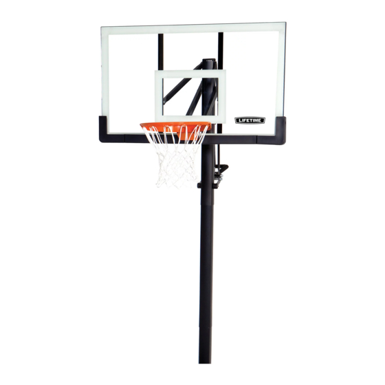
Frame pads and Backboard
Graphics may vary from the
system pictured here.
TABLE OF CONTENTS
Icon Legend................................2
Notices....................................3
Ground Preparation.....................4
(x2)
Pole Assembly.............................8
Backboard to Rim Assembly......11
Backboard to Pole Assembly.......15
Handle Assembly......................21
(x1)
Final Assembly..........................30
Maintenance Instructions..........35
Warning Sticker........................37
Registration........................38
Warranty................................39
(x3)
MODEL# AND PRODUCT ID
(you will need both when contacting us)
Model Number: 90469
Product ID:
Advertisement
Table of Contents

Related Manuals for Lifetime PUMP ADJUST 90469


Summary of Contents for Lifetime PUMP ADJUST 90469
-
Page 1: Table Of Contents
Level 640 lb / 291 kg (x1) (x1) (x3) MODEL# AND PRODUCT ID QUESTIONS? CONTACT LIFETIME CUSTOMER SERVICE: (you will need both when contacting us) Model Number: 90469 Call: 1-800-225-3865 For Customer Service in Mainland Live Chat: www.lifetime.com Product ID: Europe and the United Kingdom, (click on “Ask An Expert”... -
Page 2: Icon Legend
ICON LEGEND • Indicates special heed should be taken when reading. • Indicates the parts to be used for a section. • Indicates no parts required for a specifi c section. • Indicates the hardware to be used for a section. •... -
Page 3: Notices
WARNINGS & NOTICES SAFETY INSTRUCTIONS FAILURE TO FOLLOW THESE WARNINGS MAY RESULT IN SERIOUS INJURY OR PROPERTY DAMAGE AND WILL VOID WARRANTY. Owner must ensure that all players know and follow these rules for safe operation of the system. To ensure safety, do not attempt to assemble this product without following the instructions carefully. Check entire box and inside all packing material for parts and/or additional instruction material. -
Page 4: Ground Preparation
GROUND PREPARATION HARDWARE REQUIRED PARTS REQUIRED Metal Parts ALE (x1) Paper Parts BGW (x1) TOOLS REQUIRED 30" Rebar Level 640 lb / 291 kg... - Page 5 SECTION 1 (CONTINUED) TOOLS AND HARDWARE REQUIRED 640 lb / 291 kg • Dig a round hole 24" deep and 21" in diameter. If you live in an area where frost heaves may pose a problem, consult your local building inspector to determine the proper hole depth.
- Page 6 SECTION 1 (CONTINUED) TOOLS AND HARDWARE REQUIRED 30" Rebar • Slide the dimpled end of the Bottom Pole (ALE) into the cement up to the 16-inch mark. Position the pole next to the playing surface. For regulation courts, the Alignment Frame (BGW) should cross the playing surface at the middle of the scored measurements.
- Page 7 SECTION 1 (CONTINUED) TOOLS AND HARDWARE REQUIRED • Mix the remaining 1/2 bag of concrete. Fill the Bottom Pole (ALE) with concrete until it reaches the top of the rebar (about 15" from the top of the pole). Tamp the concrete down in the Bottom Pole with a broom handle to remove air pockets.
-
Page 8: Pole Assembly
POLE ASSEMBLY HARDWARE REQUIRED Hardware Bag 5” ANF (x2) AAA (x2) AAF (x2) CMV (x2)* ANE (x2) • Only one Self-Drilling Screw (CMV) will be used in Section 2. Save the second Screw for use in Section 5. PARTS REQUIRED Metal Parts ALH (x1) ALL (x1) - Page 9 Son mécanisme a été conçu uniquement pour soutenir le poids du panneau et de l’anneau. N’accrochez rien au manche, à l’anneau, au panneau ni aux leviers sous peine d’endommager l’équipement et d’annuler la garantie. Lifetime Products, Inc., Clearfield, UT 84016 www.lifetime.com 1-800-225-3865 7/12/2016...
- Page 10 SECTION 2 (CONTINUED) TOOLS AND HARDWARE REQUIRED CMV (x1) • THIS STEP CANNOT BE REVERSED! Strike the end of the Pole Assembly on a piece of scrap wood or cardboard fi ve to six times. • Do not hit your feet with the Pole sections, as serious injury could occur.
-
Page 11: Backboard To Rim Assembly
BACKBOARD TO RIM ASSEMBLY HARDWARE REQUIRED Hardware Bag (x2) ADR (x4) AAV (x2) AAQ (x2) ABK (x4) Hardware shown at 50% of Actual Size Hardware shown at 25% of Actual Size ABQ (x1) AJW (x2) APZ (x1) PARTS REQUIRED Plastic Parts Metal Parts BGR (x1) AJI (x1) - Page 12 SECTION 3 (CONTINUED) TOOLS AND HARDWARE REQUIRED 1/2” (13 mm) ABQ (x1) (Not to scale) (x2) AAQ (x2) • Insert two Carriage Bolts (EAP) through the Rim Pivot Bracket (APY) as shown. • Use the 1/2” socket head from the socket head wrench to press one Push Nut (AAQ) onto one end of the Axle (ABQ).
- Page 13 SECTION 3 (CONTINUED) TOOLS AND HARDWARE REQUIRED 1/2” (13 mm) APZ (x1) BGR (x1) ABK (x2) • Insert the U-Bolt (APZ) through the upper part of the opening on the backside of the Backboard (AJI). Connect the Rim (ALX) and Plastic Guard (ALD) to the Backboard (AJI) with the hardware as shown.
- Page 14 SECTION 3 (CONTINUED) TOOLS AND HARDWARE REQUIRED 1/2” (13 mm) AJW (x2) ADR (x4) AAV (x2) ABK (x2) • Thread two Jam Nuts (AAV) all the way on to the U-Bolt (APZ). Then slide the Compression Springs (AJW) onto the U-Bolt and place the Spring Retainer Plate (AOW) over the Compression Springs.
-
Page 15: Backboard To Pole Assembly
BACKBOARD TO POLE ASSEMBLY HARDWARE REQUIRED Hardware Bag 7 1/16” AAD (x1) ANU (x2) AQB (x2) 5” ANQ (x2) AQD (x1) ANS (x8) ANP (x1) AAX (x4) ABN (x4) AOR (x6) ANK (x4) AAN (x2) ABP (x2) ANZ (x2) PARTS REQUIRED Metal Part BGO (x2) BGP (x2) - Page 16 SECTION 4 (CONTINUED) TOOLS AND HARDWARE REQUIRED 1/2” (13mm) 1/2” (13 mm) AQB (x2) AAN (x2) • Insert one end of the Tie Plate (BLC) into the slot on the Lower Extension Arm (BGP), then iInsert the opposite end of the Tie Plate (BLC) into the slot on the other Lower Extension Arm (BGP) as shown.
- Page 17 SECTION 4 (CONTINUED) SECTION 4 (CONTINUED) TOOLS AND HARDWARE REQUIRED TOOLS AND HARDWARE REQUIRED / HERRAMIENTAS Y ACCESORIOS REQUERIDOS / OUTILS ET ACCESSOIRES REQUIS 3/4”(19 mm) 7 1/16” ANZ (x2) AAD (x1) AAX (x1) AOR (x2) • Insert the Extension Arm Caps (AQC) into the ends of the Lower Extension Arms (BGP) as shown. •...
- Page 18 SECTION 4 (CONTINUED) TOOLS AND HARDWARE REQUIRED 5” 3/4” (19 mm) AQD (x1) ABN (x2) AAX (x1) ANK (x2) • Place the Cap (ALM) to the Top Pole (ALH). Then attach the Upper Extension Arms (BGO) to the Top Pole (ALH) with the hardware as shown.
- Page 19 SECTION 4 (CONTINUED) TOOLS AND HARDWARE REQUIRED 3/4” (19 mm) ANQ (x2) 11/16” (18 mm) ABP (x2) AOR (x2) ANP (x1) • Rest the Rim on cardboard to prevent scratching, then secure the Lower Extension Arms (BGP) to the Backboard (AJI) with the hardware shown.
- Page 20 SECTION 4 (CONTINUED) TOOLS AND HARDWARE REQUIRED 3/4” (19 mm) ANK (x2) AAX (x2) ABN (x2) AOR (x2) ANS (x8) ANU (x2) • Attach the Upper Extension Arms (BGO) to the Backboard (AJI) with the hardware as shown. • Tighten the Nuts until they are fl...
-
Page 21: Parts Identifier
PARTS IDENTIFIER This page intentionally left blank... - Page 22 PARTS IDENTIFIER Metal Parts ALE (x1) ALL (x1) ALH (x1) ALX (x1) ALF (x1) • Warning Sticker applied to side not shown CMR (x2) BGO (x2) BGP (x2) CKM (x2) 31” ALS (x2) BGR (x1) BLC (x1) CKJ (x1) AMA (x1)
- Page 23 PARTS IDENTIFIER Plastic Parts AKF (x1) AKG (x1) AKP (x1) AJI (x1) ALM (x1) CKH (x1) CKI (x1) BGW (x1) BAA (x1) AJQ (x1) ALD (x1) BAB (x1) AQC (x2) AKZ (x1) CKG (x2) HARDWARE REQUIRED...
- Page 24 PARTS IDENTIFIER This page intentionally left blank...
-
Page 25: Handle Assembly
HANDLE ASSEMBLY HARDWARE REQUIRED Hardware Bag 6” ACX (x1) CKW (x1) ANK (x2) 7 1/16” FHM (x1) AAD (x1) BFI (x1) ABB (x1) 1/2” AAX (x3) AAW (x2) ANZ (x3) ABN (x4) CKX (x2) CKV (x2) ADT (x7) AOR (x2) AAO (x1) CKY (x2) CKU (x2) - Page 26 HANDLE ASSEMBLY PARTS REQUIRED Metal Part / Pieza de metal Pièce en métal 31” ALS (x2) CKM (x2) CMR (x2) CKJ (x1) Plastic Parts/ Piezas de plástico Pièces en plastique AKF (x1) AKG (x1) CKG (x2) CKI (x1) CKH (x1) TOOLS REQUIRED 7/16"...
- Page 27 SECTION 5 (CONTINUED) TOOLS AND HARDWARE REQUIRED 1/2" (13 mm) ACX (x1) AAO (x1) 7/16" (11 mm) AEB (x2) AAB (x2) 1/4” 1/4” CKZ (x1) • Slide the Gas Spring Cover (AKG) onto the Gas Spring (AKF) as shown. • Align the holes in the Gas Spring Cover (AKG) and the Gas Spring (AKF) with the holes in the Pole Bracket (ALL), and attach the Gas Spring assembly to the Pole Bracket with the hardware shown.
- Page 28 SECTION 5 (CONTINUED) TOOLS AND HARDWARE REQUIRED 9/16" (14 mm) 6” CKW (x1) BFI (x1) • Slide the Link Cap (CKG) onto the Pump Adjust Link (CKM). Repeat this for the second Link, with the Link Cap fl ipped over. •...
- Page 29 SECTION 5 (CONTINUED) TOOLS AND HARDWARE REQUIRED 9/16” (14 mm) ADT (x7) FHM (x1) ABB (x1) CKV (x2) • Position the Handle Frame (CKJ) inside of the Top Handle (CKH) and Bottom Handle (CKI) as shown, and secure with the hardware shown.
- Page 30 SECTION 5 (CONTINUED) TOOLS AND HARDWARE REQUIRED 1/2” 3/4" (19 mm) AAW (x1) AAX (x1) ANZ (x1) ABN (x2) CKX (x2) • Line up the hardware and spacers shown with the hole nearest to the pole on the Pump Adjust Links (CKM) and the Pump Adjust Actuators (CMR).
- Page 31 SECTION 5 (CONTINUED) TOOLS AND HARDWARE REQUIRED 7 1/16” 3/4" (19 mm) AAD (x1) ANZ (x2) AAX (x1) AOR (x2) CKT (x1) • Connect the Rear Lifter Arms (ALS) to the inside of the Long Extension Arms (AKB) with the hardware shown. Place a Spacer (CKT) between the Rear Lifter Arms as shown, with a Spacer (ANZ) between the Rear Lifter Arms and the Long Extension Arms on each side.
- Page 32 SECTION 5 (CONTINUED) TOOLS AND HARDWARE REQUIRED 1/2” 3/4" (19 mm) AAW (x1) AAX (x1) ANK (x2) ABN (x2) CKU (x2) CKY (x2) 5.10 • Finish connecting the Handle Assembly to the Gas Spring (AKF) with the hardware shown. Make sure to place a Nylon Washer (ANK) between the Gas Spring and the Handle Assembly on each side of the Handle Assembly as shown.
- Page 33 SECTION 5 (CONTINUED) TOOLS AND HARDWARE REQUIRED AKH (x1) 5.11 • Apply grease from the Grease Packet (AKH) on to the Gas Shock Rod (CKZ).
-
Page 34: Final Assembly
FINAL ASSEMBLY HARDWARE REQUIRED Hardware Bag ADP (x10) CMV (x1)* • Screw CMV is taken from the remaining hardware in Bag BCO, which was used in Section 1 of this manual. PARTS REQUIRED Plastic Parts AJQ (x1) BAA (x2) BAB (x1) AKZ (x1) AKP (x1) TOOLS REQUIRED... - Page 35 SECTION 6 (CONTINUED) TOOLS AND HARDWARE REQUIRED ADP (x10) • Attach the Net (AKZ) to the Rim (ALX). • Remove the plastic fi lm from the Backboard (AJI). • Attach the Center Frame Pad (AJQ) to the Backboard • Attach the Corner Frame Pads (BAA and BAB) to the in the location shown with the hardware indicated.
- Page 36 SECTION 6 (CONTINUED) TOOLS AND HARDWARE REQUIRED • BEFORE CONTINUING: It is critical that the instructions in the following steps are followed exactly. Failure to properly orient and align the pole sections will render the pole unusable. If the pole sections are assembled incorrectly, you will have to purchase new pole sections from our Customer Service Department.
- Page 37 SECTION 6 (CONTINUED) TOOLS AND HARDWARE REQUIRED CMV (x1) • While two people continue to hold the assembly in place, set a block of Scrap Wood on top of the Rigid Arms and strike it 5-6 times with a hammer or mallet. You must have wood on top of the Arms before hitting them with a hammer to prevent scratching the powder coating.
- Page 38 SECTION 6 (CONTINUED) TOOLS AND HARDWARE REQUIRED • Raise the Backboard until it would not go futher. Use a pencil to mark where the bottom of the Gas Spring Cover (AKG) meets the Gas Spring (AJR). Squeeze the Gas Spring Cover and apply the Height Adjust Sticker (AKP) to the back of the Gas Spring, lining up the 10' line with the pencil mark.
- Page 39 MAINTENANCE The life of your basketball system depends on many variables. The climate, exposure to corrosives such as salt, pesticides, or herbicides, and excessive use or misuse can all contribute to Pole failure, which may cause property damage or personal injury. Check your basketball system frequently for loose hardware, excessive wear, and signs of corrosion.
- Page 40 NOTES / REMARQUES / NOTAS...
-
Page 41: Warning Sticker
N’accrochez rien au manche, à l’anneau, au panneau ni aux leviers sous peine d’endommager l’équipement et d’annuler la garantie. Lifetime Products, Inc., Clearfield, UT 84016 www.lifetime.com 7/12/2016 # 1176611... -
Page 42: Registration
. And you can rest assured that Lifetime ® will not sell or provide your personal data to other third parties, or allow them to use your personal data for their own purposes. We invite you to read our privacy policy at www.lifetime.com REGISTER today! - Page 43 2. This warranty is nontransferable and is expressly limited to the repair or replacement of defective product. If the product is defective within the terms of this warranty, Lifetime Products, Inc. will repair or replace defective parts at no cost to the purchaser.
- Page 44 ® ENHANCE YOUR LIFETIME PURCHASE BY ADDING ACCESSORIES OR OTHER GREAT PRODUCTS ® To purchase accessories or other Lifetime products, visit us at: www.lifetime.com Or call: 1-800-424-3865 7:00 am–5:00 pm (M–F) MST and 9:00 am–1:00 pm Saturday MST www.lifetime.com...
Need help?
Do you have a question about the PUMP ADJUST 90469 and is the answer not in the manual?
Questions and answers