Lifetime PUMP ADJUST 90469 Assembly Instructions Manual
Basketball system
Hide thumbs
Also See for PUMP ADJUST 90469:
- Assembly instructions manual (44 pages) ,
- Owner's manual (60 pages)
Table of Contents
Advertisement
Quick Links
PUMP ADJUST
BASKETBALL SYSTEM
MODEL 90469
BEFORE ASSEMBLY:
• Before you start, make sure you have the required
amount of concrete and rebar (not included)
equires, at least, 3 days for concrete to cure, plus 3-4
• R
hours to complete assembly steps
3 people recommended for setup
• Requires at least
WATCH THE INSTRUCTIONAL VIDEO ON YOUTUBE
Scan the code, or visit go.lifetime.com/90469-fullassembly
YouTube
and the YouTube logo are trademarks of Google, LLC.
®
Save this instruction in the event that the manufacturer must be contacted for replacement parts.
TOOLS REQUIRED
1/2" (≈13mm)
9/16" (≈14mm)
(x2)
1/2" (≈13mm)
7/16" (≈11mm)
(x1)
30" Rebar
Level
QUESTIONS?
CONTACT LIFETIME CUSTOMER SERVICE:
Dial 1-800-225-3865
®
11/16" (≈18mm)
(x2)
(x2)
(x1)
(x1)
5/16" Nut Driver
(x1)
640 lb (≈291kg)
(x1)
Live Chat:
www.lifetime.com/customerservice/home
(Click on the "LIVE CHAT" tab)
ASSEMBLY INSTRUCTIONS
3/4" (≈19mm)
1/2" (≈13mm)
(x2)
(x1)
(x1)
(x1)
For Customer Service in Mainland Europe
and the United Kingdom,
E-mail: csinternational@lifetime.com
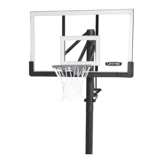
Frame pads and Backboard
Graphics may vary from the
system pictured here.
TABLE OF CONTENTS
Icon legend...................................................2
Warnings & notices......................................3
Ground preparation.......................................4
(x2)
Pole assembly...............................................9
Backboard-to-rim assembly......................12
Backboard-to-pole assembly.....................17
Handle assembly........................................23
(x1)
Final assembly............................................32
Maintenance.............................................37
Warning sticker...........................................38
Registration..............................................42
Warranty....................................................43
(x3)
Model Number: 90469
Product ID:
Advertisement
Table of Contents

Related Manuals for Lifetime PUMP ADJUST 90469


Summary of Contents for Lifetime PUMP ADJUST 90469
-
Page 1: Table Of Contents
3 people recommended for setup • Requires at least WATCH THE INSTRUCTIONAL VIDEO ON YOUTUBE Scan the code, or visit go.lifetime.com/90469-fullassembly Frame pads and Backboard YouTube and the YouTube logo are trademarks of Google, LLC. -
Page 2: Icon Legend
ICON LEGEND / LÉGENDE DES ICÔNES / LEYENDA DE ÍCONOS • Indicates special heed should be taken when reading. • Indique qu’une attention spéciale doit être portée à la lecture. • Indica que uno debe prestar atención al leer. • Indicates the parts (or no parts) required for a section. •... -
Page 3: Warnings & Notices
WARNINGS & NOTICES SAFETY INSTRUCTIONS FAILURE TO FOLLOW THESE WARNINGS MAY RESULT IN SERIOUS INJURY OR PROPERTY DAMAGE AND WILL VOID WARRANTY. Owner must ensure that all players know and follow these rules for safe operation of the system. To ensure safety, do not attempt to assemble this product without following the instructions carefully. Check entire box and inside all packing material for parts and/or additional instruction material. - Page 4 INITIAL SETUP HARDWARE REQUIRED PARTS REQUIRED Metal parts ALE (x1) Plastic parts BGW (x1) TOOLS REQUIRED (≈4-6) (x1) (x1) (x1) (x1) Concrete mix 640 lb (291 kg)
- Page 5 SECTION 1 (CONTINUED) TOOLS AND HARDWARE REQUIRED • Dig a round hole 24” (≈61 cm) deep and 21” (≈53 cm) in diameter. If you live in an area where frost heaves may pose a problem, consult your local building inspector to determine the proper hole depth. The edge of the hole should be fl...
- Page 6 SECTION 1 (CONTINUED) TOOLS AND HARDWARE REQUIRED 640 lb (291 kg) • Stack bricks in the hole for the bottom pole to stand on. Stack enough bricks in the hole so that the 16-inch (40.6 cm) mark on the pole is even with the top edge of the playing surface.
- Page 7 SECTION 1 (CONTINUED) TOOLS AND HARDWARE REQUIRED (x1) • Use a level to make sure the bottom pole is standing vertical. Form the cement into a downward slope away from the pole to allow water runoff. Failure to do so may result in premature rusting of the pole. Slope •...
- Page 8 SECTION 1 (CONTINUED) TOOLS AND HARDWARE REQUIRED (x1) • Check the pole several times within the fi rst hour to make sure that all sides are vertical and that the 16-inch mark (40.6 cm) remains level with the surface. •...
-
Page 9: Pole Assembly
POLE ASSEMBLY HARDWARE REQUIRED 5” ANF (x2) AAA (x2) AAF (x2) CMV (x2)* ANE (x2) • Only one self-drilling screw (CMV) will be used in Section 2. Save the second Screw for use in Section 5. PARTS REQUIRED Metal Parts ALH (x1) ALL (x1) ALF (x1) - Page 10 Ne rien accrocher au manche, à garantía. l’anneau, au panneau ni aux leviers sous peine d’endommager l’équipement et d’annuler la garantie. Large Holes Small Holes Lifetime Products, Inc., Clearfield, UT 84016 www.lifetime.com 7/12/2016 1-800-225-3865 # 1176611...
- Page 11 SECTION 2 (CONTINUED) TOOLS AND HARDWARE REQUIRED CMV (x1) 5/16” Nut Driver • THIS STEP CANNOT BE REVERSED! Strike the end of the pole assembly on a piece of scrap wood or cardboard fi ve to six times. WARNING The Poles must be seated together! Poles must be struck on a hard surface five to six times! Failure to seat the Poles correctly could allow the...
-
Page 12: Backboard-To-Rim Assembly
BACKBOARD-TO-RIM ASSEMBLY HARDWARE REQUIRED EAP (x2) ADR (x4) AAV (x2) ABK (x4) AAQ (x2) Hardware shown at 50% of Actual Size Hardware shown at 25% of Actual Size ABQ (x1) AJW (x2) APZ (x1) PARTS REQUIRED Plastic Parts Metal Parts BGR (x1) AJI (x1) AMA (x1) - Page 13 AAQ (x1) • In case of any troubles with this section, scan the code below to view a video on its assembly. • http://go.lifetime.com/90469-section3 • Insert two carriage bolts (EAP) through the rim pivot bracket (APY) as shown. • Use the 1/2" (≈13mm) socket from the socket wrench to press one push nut (AAQ) onto one end of the axle (ABQ).
- Page 14 SECTION 3 (CONTINUED) TOOLS AND HARDWARE REQUIRED ABQ (x1) (Not to scale) • It’s easier to do steps 3.3–3.8 on a box, table, chair or similar. Insert the ends of rim pivot bracket into the housing of the Slam-It Pro™ rim (ALX) and align the holes. •...
- Page 15 SECTION 3 (CONTINUED) TOOLS AND HARDWARE REQUIRED 1/2” (≈13 mm) APZ (x1) 1/2” (≈13 mm) BGR (x1) ABK (x2) AAQ (x1) • Slide the push nut over the axle to secure the pivot bracket in place. • Set the backboard face down on the box, table, chair or similar with the lower edge hanging over as indicated. Insert the U-bolt (APZ) through the upper part of the opening on the backside of the backboard (AJI).
- Page 16 SECTION 3 (CONTINUED) TOOLS AND HARDWARE REQUIRED 1/2” (≈13 mm) AJW (x2) ADR (x4) AAV (x2) ABK (x2) • Flip the assembly over. Thread two jam nuts (AAV) all the way on to the U-bolt (APZ). Then slide the compression springs (AJW) onto the U-bolt and place the spring retainer plate (AOW) over the compression springs.
-
Page 17: Backboard-To-Pole Assembly
BACKBOARD-TO-POLE ASSEMBLY HARDWARE REQUIRED 7 1/16 in/po (≈18cm) AAD (x1) ANU (x2) AQB (x2) 5 in/po (≈13cm) ANQ (x2) AQD (x1) ANS (x8) ANP (x1) AAX (x4) ABN (x4) AOR (x6) AAN (x2) ANK (x4) ABP (x2) ANZ (x2) PARTS REQUIRED Metal Part BGO (x2) BGP (x2) - Page 18 • In case of any troubles with this section, scan the code below to view a video on its assembly. • http://go.lifetime.com/90469-section4 • Insert one end of the tie plate (BLC) into the slot on the lower extension arm (BGP), then insert the opposite end of the tie plate into the slot on the other lower extension arm as indicated.
- Page 19 SECTION 4 (CONTINUED) SECTION 4 (CONTINUED) TOOLS AND HARDWARE REQUIRED 3/4" (≈19mm) 7 1/16 in/po (≈18cm) ANZ (x2) AAD (x1) AAX (x1) AOR (x2) • Insert the extension arm caps (AQC) into the ends of the lower extension arms (BGP) as shown. •...
- Page 20 SECTION 4 (CONTINUED) TOOLS AND HARDWARE REQUIRED 5 in/po (≈13cm) 3/4" (≈19mm) AQD (x1) ABN (x2) AAX (x1) ANK (x2) • Place the cap (ALM) to the pop pole. Then attach the upper extension arms (BGO) to the top pole with the hardware as shown. •...
- Page 21 SECTION 4 (CONTINUED) TOOLS AND HARDWARE REQUIRED 3/4" (≈19mm) ANQ (x2) 11/16" (≈18mm) ABP (x2) AOR (x2) ANP (x1) • Rest the rim on cardboard to prevent scratching, then secure the lower extension arms to the backboard with the hardware shown.
- Page 22 SECTION 4 (CONTINUED) TOOLS AND HARDWARE REQUIRED 3/4” (≈19mm) ANK (x2) AAX (x2) ABN (x2) AOR (x2) ANS (x8) ANU (x2) • Attach the upper extension arms to the backboard with the hardware as shown. • Tighten the nuts until they are fl...
-
Page 23: Parts Identifier
PARTS IDENTIFIER This page intentionally left blank... - Page 24 PARTS IDENTIFIER Metal Parts ALE (x1) ALL (x1) • Warning Sticker applied to side not shown ALF (x1) ALX (x1) ALH (x1) CMR (x2) BGO (x2) BGP (x2) CKM (x2) ALS (x2) BGR (x1) BLC (x1) CKJ (x1) AMA (x1)
- Page 25 PARTS IDENTIFIER Plastic Parts AKF (x1) AKG (x1) AKP (x1) AJI (x1) ALM (x1) CKH (x1) CKI (x1) BGW (x1) BAA (x1) AJQ (x1) ALD (x1) BAB (x1) AQC (x2) AKZ (x1) CKG (x2) HARDWARE REQUIRED...
- Page 26 PARTS IDENTIFIER This page intentionally left blank...
-
Page 27: Handle Assembly
HANDLE ASSEMBLY HARDWARE REQUIRED 6” ACX (x1) CKW (x1) ANK (x2) 7 1/16 in/po (≈18cm) 7 1/16" (17,9 cm) FHM (x1) AAD (x1) ABB (x1) BFI (x1) 6 1/2 in/po (≈17cm) AAX (x3) AAW (x2) ANZ (x3) ABN (x4) CKX (x2) CKV (x2) ADT (x7) AOR (x2) - Page 28 HANDLE ASSEMBLY PARTS REQUIRED Metal Parts ALS (x2) CKM (x2) CMR (x2) CKJ (x1) Plastic Parts AKF (x1) AKG (x1) CKG (x2) CKI (x1) CKH (x1) TOOLS REQUIRED 7/16" (≈11mm) 1/2" (≈13mm) 9/16" (≈14mm) 3/4" (≈19mm)
- Page 29 AAO (x1) • In case of any troubles with this section, scan the code below to view a video on its assembly. • http://go.lifetime.com/90469-section5 • Slide the Gas Spring Cover (AKG) onto the Gas Spring (AKF) as shown. • Align the holes in the Gas Spring Cover (AKG) and the Gas Spring (AKF) with the holes in the Pole Bracket (ALL), and attach the Gas Spring assembly to the Pole Bracket with the hardware shown.
- Page 30 SECTION 5 (CONTINUED) TOOLS AND HARDWARE REQUIRED 6” 9/16" (≈14mm) 7/16" (≈11mm) CKW (x1) BFI (x1) AEB (x2) AAB (x2) CKZ (x1) • Connect the Gas Shock Rod (CKZ) to the Gas Spring in the location pictured using the hardware shown. •...
- Page 31 SECTION 5 (CONTINUED) TOOLS AND HARDWARE REQUIRED 9/16” (≈14mm) ADT (x7) FHM (x1) ABB (x1) CKV (x2) • Position the Handle Frame (CKJ) inside of the Top Handle (CKH) and Bottom Handle (CKI) as shown, and secure with the hardware shown.
- Page 32 SECTION 5 (CONTINUED) TOOLS AND HARDWARE REQUIRED 3/4" (≈19mm) 6 1/2 in/po (≈17cm) AAW (x1) AAX (x1) ANZ (x1) ABN (x2) CKX (x2) • Line up the hardware and spacers shown with the hole nearest to the pole on the pump adjust links and the pump adjust actuators.
- Page 33 SECTION 5 (CONTINUED) TOOLS AND HARDWARE REQUIRED 7 1/16 in/po (≈18cm) 3/4" (≈19mm) AAD (x1) ANZ (x2) AAX (x1) AOR (x2) CKT (x1) • Connect the rear lifter arms (ALS) to the inside of the lower extension arms with the hardware shown. Place the black spacer (CKT) between the rear lifter arms as shown, with a spacer (ANZ) between the rear lifter arms and the long extension arms on each side.
- Page 34 SECTION 5 (CONTINUED) TOOLS AND HARDWARE REQUIRED 6 1/2 in/po (≈17cm) 3/4" (≈19mm) AAW (x1) AAX (x1) ANK (x2) ABN (x2) 5.10 CKU (x2) CKY (x2) • Finish connecting the handle assembly to the gas spring (AKF) with the hardware shown. Make sure to place a nylon washer (ANK) between the gas spring and the handle assembly on each side of the handle assembly as shown.
- Page 35 SECTION 5 (CONTINUED) TOOLS AND HARDWARE REQUIRED AKH (x1) 5.11 • Apply grease from the Grease Packet (AKH) on to the Gas Shock Rod (CKZ).
-
Page 36: Final Assembly
FINAL ASSEMBLY HARDWARE REQUIRED ADP (x10) CMV (x1)* • Screw CMV is taken from the remaining hardware in bag BCO, which was used in section 1 of this manual. PARTS REQUIRED Plastic Parts AJQ (x1) BAA (x2) BAB (x1) AKZ (x1) AKP (x1) TOOLS REQUIRED... - Page 37 • In case of any troubles with this section, scan the code below to • Remove the plastic fi lm from the backboard (AJI). view a video on its assembly. • http://go.lifetime.com/90469-section6 • Attach the center frame pad (AJQ) to the backboard • Attach the corner frame pads (BAA and BAB) to the...
- Page 38 SECTION 6 (CONTINUED) TOOLS AND HARDWARE REQUIRED • IMPORTANT! All concrete from section 1 must have been allowed to cure for at least 72 hours before continuing. It is critical that the instructions in the following steps are followed exactly. Failure to properly orient and align the pole sections will render the pole unusable.
- Page 39 SECTION 6 (CONTINUED) TOOLS AND HARDWARE REQUIRED CMV (x1) • While two people continue to hold the assembly in place, set a block of scrap wood on top of the lower extension arms and strike it 5–6 times with a hammer or mallet. You must have wood on top of the arms before hitting them with a hammer to prevent scratching the powder coating.
- Page 40 SECTION 6 (CONTINUED) TOOLS AND HARDWARE REQUIRED • Raise the backboard until the top of the rim measures 10' (≈3,05m) from the playing surface. Apply the height adjustment sticker (AKP) onto the gas spring (GFL), aligning the edge of the gas spring cover with the 10' (≈3,05m) mark on the sticker.
-
Page 41: Maintenance
MAINTENANCE The life of your basketball system depends on many variables. The climate, exposure to corrosives such as salt, pesticides, or herbicides, and excessive use or misuse can all contribute to Pole failure, which may cause property damage or personal injury. Check your basketball system frequently for loose hardware, excessive wear, and signs of corrosion. -
Page 42: Warning Sticker
Ne rien accrocher au manche, à garantía. l’anneau, au panneau ni aux leviers sous peine d’endommager l’équipement et d’annuler la garantie. Lifetime Products, Inc., Clearfield, UT 84016 www.lifetime.com 7/12/2016 # 1176611 1-800-225-3865... - Page 43 NOTES...
- Page 44 NOTES...
- Page 45 NOTES...
-
Page 46: Registration
à des tiers, et ne leur permettra pas d’utiliser vos données personnelles à leurs propres fi ns. Nous vous invitons à lire notre politique de confi dentialité à www.lifetime.com (en anglais seulement) ENREGISTRER CE PRODUIT aujourd’hui! REGISTRAR EL PRODUCTO EN LÍNEA EN WWW.LIFETIME.COM... -
Page 47: Warranty
2. This warranty is nontransferable and is expressly limited to the repair or replacement of defective product. If the product is defective within the terms of this warranty, Lifetime Products, Inc. will repair or replace defective parts at no cost to the purchaser. - Page 48 ENHANCE YOUR LIFETIME ® PURCHASE BY ADDING ACCESSORIES OR OTHER GREAT PRODUCTS To purchase accessories or other Lifetime products, visit us at: ® www.lifetime.com or dial 1-800-424-3865 www.lifetime.com © 2023 Lifetime Products, Inc., Clearfi eld, UT 1235043 2/26/2024...
Need help?
Do you have a question about the PUMP ADJUST 90469 and is the answer not in the manual?
Questions and answers