
Related Manuals for Lifetime 90023


Summary of Contents for Lifetime 90023
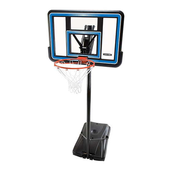
- Page 1 MODEL N° 90023 OWNER’S MANUAL OWNER’S MANUAL Keep this Product ID Number and use when contacting Customer Service:...
- Page 2 Maintaining your privacy is our long-standing policy at Lifetime. And you can rest as- sured that Lifetime will not sell or provide your personal data to other third parties, or allow them to use your personal data for their own purposes.
-
Page 3: Safety Instructions
SAFETY INSTRUCTIONS DAMAGE AND WILL VOID WARRANTY. To ensure safety, do not attempt to assemble this product without reading and materials for parts and/or additional instruction material. Before beginning assembly, identify and inventory all parts and hardware using the parts and hardware lists and Proper and complete assembly, use and supervision and/or operated properly. - Page 4 TOOLS AND PARTS REQUIRED FOR THIS ASSEMBLY 1/2” Wrench 7/16” Wrench 9/16” Wrench Phillips Screwdriver Pliers Rubber Mallet Scrap Wood Sand (362 lb) CCL-3/16” Allen Wrench Water Hose (2, included) *Two adults required to complete assembly* Only adults should set up the product. Do not allow children in the setup area until assembly is complete.
- Page 5 ASSEMBLY GUIDES Refer to the following areas throughout the instructions to assist in the assembly process: This area is located at the top, TOOLS AND HARDWARE REQUIRED FOR THIS PAGE left-hand corner of the page and indicates which tools and hardware are needed to complete the assembly steps on a page.
-
Page 6: Parts List
PARTS LIST Item Description Top Pole Middle Pole Bottom Pole Base Pole Brace Wheel Base Plug HARDWARE LIST Item Description Pole Assembly Hardware 3/8” Plug 1/2” Nylon Plug Pole to Base Assembly Hardware 5/16” Washer 1/4” Barrel Nut 3/16” Allen Wrench (not shown) Backboard to Rim Assembly Hardware 5/16”... - Page 7 HARDWARE LIST Item Description Backboard to Rim Assembly Hardware, Continued 3 1/2” U-Bolt Rim Support Channel Backboard to Pole Assembly Hardware PARTS LIST Parts shown at 10% of Actual Size Top Pole *Warning Sticker applied to side not shown Middle Pole Bottom Pole 7”...
-
Page 8: Parts Identifier
PARTS IDENTIFIER Parts shown at 10% of Actual Size Parts shown at 5% of Actual Size Base Parts shown at 25% of Actual Size Base Plug Wheel... -
Page 9: Hardware Identifier
HARDWARE IDENTIFIER POLE ASSEMBLY HARDWARE Hardware shown at Actual Size Washer 1/2” Nylon Plug 3/8” Plug POLE TO BASE ASSEMBLY HARDWARE Hardware shown at Actual Size 1/4” Barrel Nut 5/16” Washer BACKBOARD TO RIM ASSEMBLY HARDWARE Hardware shown at Actual Size 5/16”... - Page 10 HARDWARE IDENTIFIER BACKBOARD TO RIM ASSEMBLY HARDWARE (CONTINUED) Hardware shown at 25% of Actual Size 3 1/2” U-Bolt Rim Support Channel BACKBOARD TO POLE ASSEMBLY HARDWARE Hardware shown at Actual Size 6.625” (Not actual length) 6 1/2” (Not actual length)
-
Page 11: Pole Assembly
POLE ASSEMBLY HARDWARE REQUIRED Hardware shown at Actual Size 1/2” Nylon Plug 3/8” Plug Washer PARTS REQUIRED Parts shown at 10% of Actual Size Top Pole *Warning Sticker applied to side not shown Middle Pole Bottom Pole TOOLS REQUIRED Phillips Screwdriver Scrap Wood... - Page 12 TOOLS AND HARDWARE REQUIRED FOR THIS PAGE Align the hole in the Top Pole (ALH) with the slot in the slide the Top Pole over the Middle Pole. Insert a through the small hole in the Top Pole and into the slot in the Middle Pole as shown.
- Page 13 TOOLS AND HARDWARE REQUIRED FOR THIS PAGE Align the hole in the with the slot in the Bottom Pole (ALE) and slide the Middle Pole over the Bottom Pole. Insert a through the small hole in the Middle Pole and into the slot in the Bottom Pole as shown.
- Page 14 TOOLS AND HARDWARE REQUIRED FOR THIS PAGE Insert the into the small holes on the Then insert the 1/2” Nylon Plugs (ANS) into the large holes on the other side of the Middle Pole as shown. Small Holes Large Holes...
- Page 15 TOOLS AND HARDWARE REQUIRED FOR THIS PAGE ATTENTION: THIS STEP CANNOT BE REVERSED! times on a piece of scrap wood or cardboard. This must be done even if the Poles cover the slots before seating has occurred. If the do not completely cover the slots on the after seating, DO NOT COMPLETE ASSEMBLY.
- Page 16 POLE TO BASE ASSEMBLY HARDWARE REQUIRED Bag BCQ Hardware shown at Actual Size 1/4” Barrel Nut 5/16” Washer PARTS REQUIRED Part shown at 5% of Actual Size Part shown at 25% of Actual Size Wheel Base Parts shown at 10% of Actual Size 7”...
- Page 17 TOOLS AND HARDWARE REQUIRED FOR THIS PAGE Attach the fl attened end of the Pole Brace (ALI) to the with the hardware shown. Only fi nger tighten the hardware for now. Curved End Straight End Note: Repeat this step to install the other Pole Brace to the other side of the Base.
- Page 18 TOOLS AND HARDWARE REQUIRED FOR THIS PAGE 3/16" 1/2" facing down. Position the under the bottom slots of the as shown, and step onto the Base so the snaps into the upper slots of the Base as shown. Attach the Pole Braces (ALI) to the Bottom Pole (ALE) with the hardware shown, and tighten all Pole to Base assembly hardware.
- Page 19 BACKBOARD TO RIM ASSEMBLY HARDWARE REQUIRED Hardware shown at Actual Size 1/4” Center- Flange Nut Hardware shown at 25% of Actual Size 5/16” Washer 3 1/2” U-Bolt Rim Support Channel PARTS REQUIRED Part shown at 5% of Actual Size Part shown at 25% of Actual Size...
- Page 20 BACKBOARD TO RIM ASSEMBLY PARTS REQUIRED Parts shown at 10% of Actual Size TOOLS REQUIRED 1/2” Wrench 7/16” Wrench 3/8” Wrench...
- Page 21 TOOLS AND HARDWARE REQUIRED FOR THIS PAGE 7/16” (Not to scale) Slide the 3 1/2” U-Bolt (APK) through the as shown. Notch Fold up the sides of the Inner Guard (BDM) and place it between the , two 1/2” x 2 5/16”...
- Page 22 TOOLS AND HARDWARE REQUIRED FOR THIS PAGE (Not to scale) Place the Rim Support Channel (AOX) so that the fl at side with holes is positioned against 3 1/2” U-Bolt (APK) through the holes above the recess as shown.
- Page 23 TOOLS AND HARDWARE REQUIRED FOR THIS PAGE 1/2” Attach the Rim (ALX) to the by securing two 5/16” Washers (ABD) and two to the 3 1/2” U-Bolt (APK). Then insert with 5/16” Washers through the bottom Underside View Note: Tighten the 5/16” Nylock Flange Nuts (ABK) until they are fl ush with the ends of the Bolts.
- Page 24 TOOLS AND HARDWARE REQUIRED FOR THIS PAGE 3/8” Bend the outward by hand in the...
- Page 25 BACKBOARD TO POLE ASSEMBLY HARDWARE REQUIRED Hardware shown at Actual Size 6 5/8” (Not actual length) 6 1/2” (Not actual length) PARTS REQUIRED Parts shown at 10% of Actual Size 17” TOOLS REQUIRED 9/16” Wrench Rubber Mallet...
- Page 26 TOOLS AND HARDWARE REQUIRED FOR THIS PAGE 6 5/8” (Not actual length) Secure two of the Extension Arms (AKC) Note: Tighten the 1/2” Centerlock Nut (AAX) until it is fl ush with the end of the Bolt.
- Page 27 TOOLS AND HARDWARE REQUIRED FOR THIS PAGE Place the Dunk Latch (BDL) within the Outer Guard (BDN) and align the Inner Guard (BDM)
- Page 28 TOOLS AND HARDWARE REQUIRED FOR THIS PAGE 6 5/8” (Not actual length) Secure the Dunk Latch (BDL), Outer Guard (BDN), and the other two Extension Arms (AKC) hardware indicated. Note: Tighten the 1/2” Centerlock Nut (AAX) until it is fl ush with the end of the Bolt.
- Page 29 TOOLS AND HARDWARE REQUIRED FOR THIS PAGE 6 1/2” 9/16” (Not actual length) Dunk Latch (BDL) and Outer Guard (BDN) so the slots line up with the holes in the upper Extension Arms (AKC) that are closest to the WARNING Do not operate the system without the Outer detached, call our Customer Service Department.
- Page 30 TOOLS AND HARDWARE REQUIRED FOR THIS PAGE 6 5/8” (Not actual length) CAUTION: HAVE ONE ADULT HOLD THE BACKBOARD IN PLACE UNTIL THIS STEP HAS BEEN COMPLETED! the Rim on cardboard to prevent scratching. Then secure the Extension Arms (AKC) to the Pole Assembly with the hardware shown. Note: Tighten the 1/2”...
- Page 31 HARDWARE REQUIRED NO HARDWARE REQUIRED FOR THIS SECTION PARTS REQUIRED Part shown at 10% of Actual Size Part shown at Actual Size Base Plug TOOLS REQUIRED Sand (362 lb) Water Hose...
- Page 32 TOOLS AND HARDWARE REQUIRED FOR THIS PAGE (362 lb) Two adults are required to complete assembly. To prevent serious injuries, the Pole should be held down by one adult at all times while the Base is being fi lled. (362 lb of sand required) a.
- Page 33 TOOLS AND HARDWARE REQUIRED FOR THIS PAGE Two adults are required to complete assembly. To prevent serious injuries, the Pole should be held down by one adult at all times while the Base is being fi lled. a. Insert a into the in the hole closest to the Pole.
- Page 34 TOOLS AND HARDWARE REQUIRED FOR THIS PAGE Attach Net (AKZ) to the Rim (ALX). Note: If a replacement Net is needed, please call our Customer Service Department. Our Nets are shorter than average to reduce the risk of entanglement.
-
Page 35: Moving The System
OPERATION OF HEIGHT ADJUSTMENT SYSTEM To Raise the Hoop: broom handle, under the Rim and push upward. To Lower the Hoop: Raise support the weight as you lower the system. Lower MOVING THE SYSTEM WARNING: The system must only be moved by people capable of handling its weight. - Page 36 POLE CARE AND SYSTEM MAINTENANCE that have been worn or damaged through usage. Contact our Customer Service Department for replacement parts. are present, do the following: Use an emery cloth to completely remove any rust or chipped paint. Clean the area with a damp cloth and allow it to dry. Apply two coats of a rust preventative, high gloss enamel paint to the area.
- Page 37 NOTES...
- Page 38 ® ENHANCE YOUR LIFETIME PURCHASE BY ADDING ACCESSORIES OR OTHER GREAT PRODUCTS: To purchase accessories or other Lifetime Products, visit us at: www.lifetime.com Or call: 1-800-424-3865...
- Page 39 No cuelgue nada de la www.lifetime.com...
-
Page 40: Warranty Information
ALL WARRANTY CLAIMS MUST BE ACCOMPANIED BY A SALES RECEIPT. M-F 7 a.m. to 5 p.m. MST. **Call or visit our Web site for Saturday hours** Please include your dated sales receipt and photographs of damaged parts. To register the product, visit our Web site at www.lifetime.com www.lifetime.com...
Need help?
Do you have a question about the 90023 and is the answer not in the manual?
Questions and answers