Table of Contents
Advertisement
Quick Links
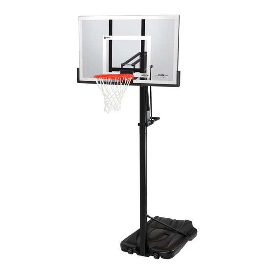
PUMP ADJUST
BASKETBALL SYSTEM
MODEL #60091
MODEL 90487
BEFORE ASSEMBLY:
• Before you start, decide how you would like to fi ll
your base (sand is recommended, see page 29).
• Assembly should take 2 people about 2-3
hours to complete.
Save this instruction in the event that the manufacturer has
to be contacted for replacement parts.
TOOLS REQUIRED
3/8", 1/2", 9/16", 3/4"
(2)
(1)
(1)
QUESTIONS?
CONTACT LIFETIME CUSTOMER SERVICE:
Call: 1-800-225-3865
7:00 am-5:00 pm (Monday-Friday) MST
and 9:00 am-1:00 pm Saturday MST
™
1/2"
(2)
(1)
1/4"
(1)
(1)
Live Chat: www.lifetime.com
(click on "Ask An Expert" tab)
Video Instructions:
www.youtube.com/lifetimeproducts
ASSEMBLY INSTRUCTIONS
(1)
(1)
3/16"
(1)
(2)
(1)
(375 lb)
For Customer Service in Mainland
Europe and the United Kingdom,
E-mail: cs@lifetimeproducts.eu
TABLE OF CONTENTS
Icon Legend................................2
Notices....................................3
Pole Assembly.............................4
Pole to Base Assembly.................9
Backboard to Rim Assembly.......13
Backboard to Pole Assembly.......19
Handle Assembly.......................23
Final Assembly..........................32
Maintenance Instructions..........36
Warning Sticker........................37
Registration........................38
Warranty................................39
MODEL# AND PRODUCT ID
(you will need both when contacting us)
Model Number: 90487
Product ID:
Advertisement
Table of Contents

Related Manuals for Lifetime PUMP ADJUST 90487


Summary of Contents for Lifetime PUMP ADJUST 90487
-
Page 1: Table Of Contents
1/4” Warning Sticker......37 Registration......38 Warranty........39 (375 lb) MODEL# AND PRODUCT ID QUESTIONS? CONTACT LIFETIME CUSTOMER SERVICE: (you will need both when contacting us) Model Number: 90487 Call: 1-800-225-3865 For Customer Service in Mainland Live Chat: www.lifetime.com Product ID: Europe and the United Kingdom, (click on “Ask An Expert”... -
Page 2: Icon Legend
ICON LEGEND • Indicates special heed should be taken when reading. • Indicates the parts to be used for a section. • Indicates no parts required for a specifi c section. • Indicates the hardware to be used for a section. •... - Page 3 WARNINGS & NOTICES / AVERTISSEMENTS ET AVIS / ADVERTENCIAS Y AVISOS SAFETY INSTRUCTIONS FAILURE TO FOLLOW THESE WARNINGS MAY RESULT IN SERIOUS INJURY OR PROPERTY DAMAGE AND WILL VOID WARRANTY. Owner must ensure that all players know and follow these rules for safe operation of the system. To ensure safety, do not attempt to assemble this product without following the instructions carefully.
-
Page 4: Pole Assembly
POLE ASSEMBLY HARDWARE REQUIRED Hardware Bag ABR (x2) AAF (x2) CMV (x2) ABE (x2) ABB (x2) PARTS REQUIRED Metal Parts Warning Sticker ALH (x1) ALF (x1) ALL (x1) ALE (x1) TOOLS REQUIRED 3/8" Electric Drill Scrap Wood Pencil Measuring Tape... - Page 5 No Son mécanisme a été conçu unique aro, el tablero ni los brazos de el sistema y anular la garantía. panneau et de l’anneau. N’accroche au panneau ni aux leviers sous peine et d’annuler la garantie. 4016 www.lifetime.com...
- Page 6 SECTION 1 (CONTINUED) TOOLS AND HARDWARE REQUIRED • Make sure the holes indicated are on the same side of the Pole assembly as the Pole Bracket. Slide the Top Pole (ALH) onto the Middle Pole (ALF) as shown. ATTENTION: THIS STEP CANNOT BE REVERSED! •...
- Page 7 SECTION 1 (CONTINUED) TOOLS AND HARDWARE REQUIRED • Slide the Middle Pole (ALF) onto the ATTENTION: THIS STEP CANNOT BE REVERSED! Bottom Pole(ALE) as shown. Make sure • In order to seat the Poles, strike each end of the Pole very the crimped side at the end of the hard fi...
- Page 8 SECTION 1 (CONTINUED) TOOLS AND HARDWARE REQUIRED CMV (x2) • After the Poles have been seated, insert two #10 x .62” Self-Tapping Screws (CMV) into the back of the Pole as shown. • For ease of installation, chuck the Self-Drilling Screws directly into the drill if your drill (see Figure 1, not available on all drills), or use a 3/8”...
-
Page 9: Pole To Base Assembly
POLE TO BASE ASSEMBLY HARDWARE REQUIRED Hardware Bag DRZ (x1) AAO (x2) AAE (x2) BTS (x1) ABD (x4) CCL (x2) PARTS REQUIRED Metal Part ” 38” AJD (x1) ALI (x2) Plastic Parts AMU (x2) AJN (x1) AJM (x1) TOOLS REQUIRED CCL-3/16”... - Page 10 SECTION 2 (CONTINUED) TOOLS AND HARDWARE REQUIRED • Screw the Base Cap (AJN) onto the Base (AJM) as shown. Rubber Gasket • Make sure the Rubber Gasket is inside the Base Cap. • Position the Pole assembly on the Base (AJM) as shown. Slide the 21 3/4” Axle (AJD) through one of the Wheels (AMU) and into the Base (AJM).
- Page 11 SECTION 2 (CONTINUED) TOOLS AND HARDWARE REQUIRED 1/2" (x2) AAE (x2) AAO (x2) ABD (x4) • Attach the fl attened end of the Pole Brace (ALI) to the Base (AJM) with the hardware shown. Only fi nger tighten the hardware. •...
- Page 12 SECTION 2 (CONTINUED) TOOLS AND HARDWARE REQUIRED 3/16” CCL (x2) DRZ (x1) BTS (x1) 1/2" (x2) • Attach the Pole Braces (ALI) to the Bottom Pole (ALE) with the hardware shown. • Tip the system forward and rest the Pole on the ground. Do not stand the system up until it is fi lled with either sand or water later in the assembly.
-
Page 13: Backboard To Rim Assembly
BACKBOARD TO RIM ASSEMBLY HARDWARE REQUIRED Hardware Bag AOU (x1) ABB (x4) ADR (x4) DFE (x4) ABQ (x1) APY (x1) EAP (x2) AAV (x2) AOW (x1) AJW (x2) AAQ (x2) ABK (x4) PARTS REQUIRED Metal Parts AJI (x1) AMA (x1) Plastic Parts / Pièces en plastique / Piezas de plástico... - Page 14 SECTION 3 (CONTINUED) TOOLS AND HARDWARE REQUIRED 9/16" (11 mm) (x2) EAP (x2) APY (x1) DFE (x4) ABB (x4) • Attach the Backboard Brackets (AMY) to the Backboard using the hardware indicated. • Insert two Carriage Bolts (EAP) through each hole in the Rim Pivot Bracket (APY).
- Page 15 SECTION 3 (CONTINUED) TOOLS AND HARDWARE REQUIRED 1/2" (13mm) (x1) ABQ (x1) AAQ (x2) • Use the 1/2" (13 mm) socket head from the socket head wrench to press one Push Nut (AAQ) onto one end of the Axle (ABQ). 1/2"...
- Page 16 SECTION 3 (CONTINUED) TOOLS AND HARDWARE REQUIRED 1/2" (13mm) AOU (x1) (x1) ABK (x2) • Lay the Backboard (AJI) on a table or bench. Insert the U-Bolt (AOU) through the upper part of the opening on the backside of the Backboard (AJI) as shown. •...
- Page 17 SECTION 3 (CONTINUED) TOOLS AND HARDWARE REQUIRED 1/2" (13 mm) (x1) AJW (x2) AOW (x1) AAV (x2) ABK (x2) • Thread the Jam Nuts (AAV) all the way down on the U-Bolt (AOU) as shown. • Slide the Compression Springs (AJW) onto the U-Bolt (AOU), and place the Spring Retainer Plate (AOW) over the Compression Springs.
- Page 18 SECTION 3 (CONTINUED) TOOLS AND HARDWARE REQUIRED ADR (x4) • Attach the Rim Cover Plate (AMA) to the Rim using Screws (ADR).
-
Page 19: Backboard To Pole Assembly
BACKBOARD TO POLE ASSEMBLY HARDWARE REQUIRED Hardware Bag 7 1/2” 7 1/16” AAD (x2) DFB (x2) AAX (x4) DGA (x2) ABN (x8) PARTS REQUIRED Metal Parts Plastic Part 21 1/8” (53.6 cm) AKC (x2) ALM (x1) 25 7/8” (65.7 cm) AKB (x2) TOOLS REQUIRED 3/4”... - Page 20 SECTION 4 (CONTINUED) 7 1/2” TOOLS AND HARDWARE REQUIRED 3/4” (x2) AAX (x2) DFB (x2) DGA (x2) ABN (x4) • Finger-tighten the Short Extension Arms (AKC) to the Backboard Brackets with the hardware shown. • If necessary, use a bolt to remove any excess powder coating from the holes in the Backboard Brackets.
-
Page 21: Parts Identifier
PARTS IDENTIFIER This page intentionally left blank... - Page 22 PARTS IDENTIFIER Metal Part ALH (x1) ALF (x1) Warning Sticker AJI (x1) ALE (x1) 38” ALI (x2) CKJ (x1) 21 1/8” (53.6 cm) 25 7/8” (65.7 cm) AKC (x2) AKB (x2) ” AJD (x1) CMR (x2) ALL (x1) DFD (x1) ALX (x1) AMY (x2) AMA (x1)
- Page 23 PARTS IDENTIFIER Plastic Parts AKG (x1) AKZ (x1) AKF (x1) AJM (x1) CKG (x2) CKI (x1) CKH (x1) ALD (x1) AKP (x1) AJQ (x1) ALM (x1) AJN (x1) BAA (x1) AMU (x2) BAB (x1) HARDWARE REQUIRED...
- Page 24 PARTS IDENTIFIER This page intentionally left blank...
- Page 25 SECTION 4 (CONTINUED) TOOLS AND HARDWARE REQUIRED 3/4” (x2) 7 1/16” AAD (x1) ABN (x2) AAX (x1) • Line up the holes in the Top Pole with the holes in the Lower Extension Arms (AKB) as shown. Secure the Lower Extension Arms to the pole assembly.
- Page 26 SECTION 4 (CONTINUED) SECTION 4 (CONTINUED) TOOLS AND HARDWARE REQUIRED TOOLS AND HARDWARE REQUIRED 3/4” (x2) 7 1/16” AAD (x1) ABN (x2) AAX (x1) • Secure the Short Extension Arms (AKC) to the Top Pole with the hardware shown. If necessary, use a rubber mallet to tap the bolt into place.
-
Page 27: Handle Assembly
HANDLE ASSEMBLY HARDWARE REQUIRED Hardware Bag 6” 5 1/2” DYX (x1) DYY (x2) 7 1/16” FHM (x1) DIH (x1) AAD (x1) APC (x2) ANZ (x1) AEB (x2) ANK (x2) ABN (x4) CKV (x2) CKT (x1) ECE (x2) CKZ (x1) ADT (x7) CKY (x2) CYN (x1) AAB (x2) - Page 28 HANDLE ASSEMBLY PARTS REQUIRED Metal Part 31” ALS (x2) CKM (x2) CMR (x2) CKJ (x1) Plastic Parts AKF (x1) AKG (x1) CKG (x2) CKI (x1) CKH (x1) TOOLS REQUIRED 7/16" (11 mm) 1/2" (13 mm) 9/16" (14 mm) 3/4" (19 mm) 1/4”...
- Page 29 SECTION 5 (CONTINUED) TOOLS AND HARDWARE REQUIRED 1/2" (13 mm) 7/16" (11 mm) AEB (x2) DIH (x1) AAB (x2) 1/4” 1/4” 1/4” CYN (x1) CKZ (x1) • Connect the Gas Shock Rod (CKZ) to the Gas Spring in the location pictured and slide the Gas Spring Cover (AKG) onto the Gas Spring (AKF) as shown.
- Page 30 SECTION 5 (CONTINUED) TOOLS AND HARDWARE REQUIRED 9/16" (14 mm) 5 1/2” ABB (x1) DYX (x1) • Slide the Link Cap (CKG) onto the Pump Adjust Link (CKM). Repeat this for the second Link, with the Link Cap fl ipped over. •...
- Page 31 SECTION 5 (CONTINUED) TOOLS AND HARDWARE REQUIRED 9/16” (14 mm) ADT (x7) FHM (x1) ABB (x1) CKV (x2) • Position the Handle Frame (CKJ) inside of the Top Handle (CKH) and Bottom Handle (CKI) as shown, and secure with the hardware shown.
- Page 32 SECTION 5 (CONTINUED) TOOLS AND HARDWARE REQUIRED 6” 3/4" (19 mm) DYY (x1) AAX (x1) ANZ (x1) ABN (x2) ECE (x2) • Line up the hardware and spacers shown with the hole nearest to the pole on the Pump Adjust Links (CKM) and the Pump Adjust Actuators (CMR).
- Page 33 SECTION 5 (CONTINUED) TOOLS AND HARDWARE REQUIRED 7 1/16” 3/4" (19 mm) AAD (x1) AAX (x1) CKT (x1) • Connect the Rear Lifter Arms (ALS) to the inside of the Long Extension Arms (AKB) with the hardware shown. Place a Spacer (CKT) between the Rear Lifter Arms as shown.
- Page 34 SECTION 5 (CONTINUED) TOOLS AND HARDWARE REQUIRED 6” 3/4" (19 mm) DYY (x1) AAX (x1) ANK (x2) ABN (x2) APC (x2) CKY (x2) 5.10 • Connect the Handle Assembly to the Gas Spring (AKF) with the hardware shown. Place a 1/2” Nylon Washer (ANK) between the Gas Spring and the Handle Assembly on each side of the Handle Assembly as shown.
- Page 35 SECTION 5 (CONTINUED) TOOLS AND HARDWARE REQUIRED AKH (x1) 5.11 • Apply grease from the Grease Packet (AKH) on to the Gas Shock Rod (CKZ).
-
Page 36: Final Assembly
FINAL ASSEMBLY HARDWARE REQUIRED Hardware Bag ADP (x10) PARTS REQUIRED AKP (x1) AKZ (x1) AJQ (x1) BAA (x1) BAB (x1) TOOLS REQUIRED (x1) (375 lb) (x1) (x1) (x1) (170 kg) (x1) (x1) - Page 37 SECTION 6 (CONTINUED) / SECTION 6 (SUITE) SECCIÓN 6 (CONTINUACIÓN) TOOLS AND HARDWARE REQUIRED / OUTILS ET ACCESSOIRES REQUIS / INSTRUMENTAL Y HERRAJE REQUERIDOS (x1) (x1) ADP (x10) • Remove the plastic fi lm from the Backboard (AJI), and attach the Center Frame Pad (AJQ) to the Backboard in the location shown with the hardware indicated.
- Page 38 SECTION 6 (CONTINUED) / SECTION 6 (SUITE) SECCIÓN 6 (CONTINUACIÓN) TOOLS AND HARDWARE REQUIRED / OUTILS ET ACCESSOIRES REQUIS / INSTRUMENTAL Y HERRAJE REQUERIDOS (375 lb) 6.3A Two adults are required to complete assembly. To prevent serious injuries, the Pole should be held down by one adult at all times while the Base is being fi...
- Page 39 SECTION 6 (CONTINUED) / SECTION 6 (SUITE) SECCIÓN 6 (CONTINUACIÓN) TOOLS AND HARDWARE REQUIRED / OUTILS ET ACCESSOIRES REQUIS / INSTRUMENTAL Y HERRAJE REQUERIDOS • Attach the Net (AKZ) to the Rim (ALX). • Raise the Backboard until it would not go futher. Use a pencil to mark where the bottom of the Gas Spring Cover (AKG) meets the Gas Spring (AJR).
-
Page 40: Maintenance Instructions
MAINTENANCE INSTRUCTIONS The life of your basketball system depends on many variables. The climate, exposure to corrosives such as salt, pesticides, or herbicides, and excessive use or misuse can all contribute to Pole failure, which may cause property damage or personal injury. Check your basketball system frequently for loose hardware, excessive wear, and signs of corrosion. -
Page 41: Warning Sticker
fils électriques. mécanisme a été conçu uniquement pour soutenir le poids du panneau et de sous peine d’endommager l’équipement et d’annuler la garantie. www.lifetime.com #FS16400 10/12/2004... -
Page 42: Registration
. And you can rest assured that Lifetime will not sell or provide your personal data to other third parties, or allow them to use your personal data for their own purposes. We invite you to read our privacy policy at www.lifetime.com REGISTER today! - Page 43 2. This warranty is nontransferable and is expressly limited to the repair or replacement of defective product. If the product is defective within the terms of this warranty, Lifetime Products, Inc. will repair or replace defective parts at no cost to the purchaser.
- Page 44 ® AMÉLIOREZ VOTRE ACHAT LIFETIME EN AJOUTANT DES ACCESSOIRES OU DES AUTRES PRODUITS ® Pour acheter des accessoires ou des autres produits Lifetime , rendez-vous une visite à : www.lifetime.com Ou appelez-nous au 1-800-424-3865 Du lundi au vendredi 7 h – 17 h (HNR) et samedi 9 h – 13 h (HNR) ®...
Need help?
Do you have a question about the PUMP ADJUST 90487 and is the answer not in the manual?
Questions and answers