Table of Contents
Advertisement
Advertisement
Table of Contents

Related Manuals for Kollmorgen BDS4 Series


Summary of Contents for Kollmorgen BDS4 Series
- Page 1 Artisan Technology Group is your source for quality new and certified-used/pre-owned equipment SERVICE CENTER REPAIRS WE BUY USED EQUIPMENT • FAST SHIPPING AND DELIVERY Experienced engineers and technicians on staff Sell your excess, underutilized, and idle used equipment at our full-service, in-house repair center We also offer credit for buy-backs and trade-ins •...
- Page 2 BDS4 S ERIES NSTALLATION AND ETUP ANUAL M93100 - Issue 2 Old Number New Number MB4001H Artisan Technology Group - Quality Instrumentation ... Guaranteed | (888) 88-SOURCE | www.artisantg.com...
- Page 3 Artisan Technology Group - Quality Instrumentation ... Guaranteed | (888) 88-SOURCE | www.artisantg.com...
- Page 4 Artisan Technology Group - Quality Instrumentation ... Guaranteed | (888) 88-SOURCE | www.artisantg.com...
- Page 5 © Copyright 1993, Danaher Motion Kollmorgen. All rights reserved Printed in the United States of America NOTICE Not for use or disclosure outside of Danaher Motion Kollmorgen except under written agreement. All rights reserved. No part of this book shall be reproduced, stored in a retrieval system, or transmitted by any means (electronic, mechanical, photocopying, recording, or otherwise) without the written permission from the publisher.
- Page 6 The results of these and other efforts has encouraged industry, Industrial Drives and its parent, Kollmorgen some of the most significant innovations in the servo Corporation, continue to rank first in servo industry.
- Page 7 Artisan Technology Group - Quality Instrumentation ... Guaranteed | (888) 88-SOURCE | www.artisantg.com...
- Page 8 Artisan Technology Group - Quality Instrumentation ... Guaranteed | (888) 88-SOURCE | www.artisantg.com...
- Page 9 Artisan Technology Group - Quality Instrumentation ... Guaranteed | (888) 88-SOURCE | www.artisantg.com...
- Page 10 Artisan Technology Group - Quality Instrumentation ... Guaranteed | (888) 88-SOURCE | www.artisantg.com...
- Page 11 List of Drawings BDS4 List of Drawings A-63542……….. Motor Connection A-83908……….. Purchase Spec. for Mini-Fit, Jr.Series Connector A-83909……….. Purchase Spec. for Mini-Fit, Jr.Series Terminals A-84385……….. Outline & Dimension PSR4/5 - 12 & 20 Amp A-93031……….. Outline & Dimension PSR4/5 - 50 & 75 Amp A-93092………..
- Page 12 BDS4 1 - S HAPTER YSTEM ESCRIPTION HAPTER 1 YSTEM ESCRIPTION 1.1 INTRODUCTION Numerous Industrial Drives B Series motors with various diameters, stack lengths, and windings are also available. The information in this chapter will enable you to understand the product's basic functions and features. These concepts will allow you to apply them to your 1.3 FEATURES own unique applications.
-
Page 13: Theory Of Operation
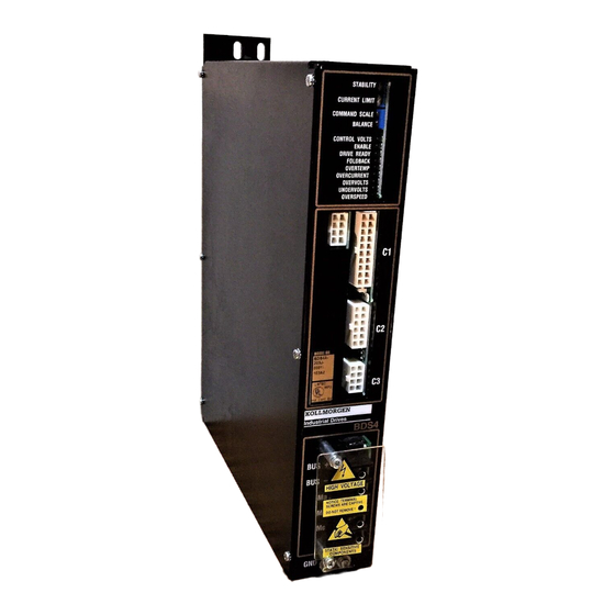
1 - S BDS4 HAPTER YSTEM ESCRIPTION from logic bus out-of-tolerance conditions and All of the compensation components necessary to motor stator short circuit conditions, both line-to- match a BDS4 amplifier to a particular motor such as, line and line-to-ground. current loop compensation, velocity loop compensation, and torque angle compensation, are •... - Page 14 BDS4 1 - S HAPTER YSTEM ESCRIPTION Figure 1.1. BDS4 and PSR4/5 (Low Current Models shown) limits the voltage rise during the is held on for too long, the shunt regulator deceleration periods. power transistor fails, or the shunt regulator load resistor becomes shorted, the fuse will •...
- Page 15 1 - S BDS4 HAPTER YSTEM ESCRIPTION The shunt regulator also includes a duty These signals are associated with the cycle limit circuit to protect against motor system resolver. A 7.0 kHz excessive load resistor heating. If the excitation signal is generated in the average duty cycle limit is exceeded, the BDS4 and sent to the resolver.
- Page 16 The shunt regulator circuit is between the rotor flux and the stator flux—commonly referred to deactivated. as torque angle. Industrial Drives, A Kollmorgen Division, Patented Numbers 4,447,771; 4,479,078; and 4,490,661. Artisan Technology Group - Quality Instrumentation ... Guaranteed | (888) 88-SOURCE | www.artisantg.com...
-
Page 17: Typical System Diagram
1 - S BDS4 HAPTER YSTEM ESCRIPTION The Drive-Up contact within the BDS4 The shunt regulator regeneration will open due to Bus undervolts. circuitry is switched from dynamic bus discharge to regular mode. Only the Control AC line input voltage is removed. - Page 18 Figure 1.2. Typical System Diagram Artisan Technology Group - Quality Instrumentation ... Guaranteed | (888) 88-SOURCE | www.artisantg.com...
-
Page 19: Installation
BDS4 2 - I HAPTER NSTALLATION HAPTER 2 NSTALLATION 2.1 INTRODUCTION to the potential for personal injury. Follow the recommended precautions and safe operating practices included with the alert symbols. The information in this chapter will familiarize you with the safety information, unpacking and "Warning"... -
Page 20: Unpacking And Inspection
2 - I BDS4 HAPTER NSTALLATION • CAPITALIZED text stresses attention to the 2.3.3 Abbreviations details of the procedure. Counter Clockwise • Underlined text emphasizes crucial words in Clockwise sentences that could be misunderstood if the DIFF CMD Differential Command word is not recognized. - Page 21 BDS4 2 - I HAPTER NSTALLATION 2.5.1 Environmental Considerations Depending on the continuous current ratings of the BDS4 and PSR4/5 modules, a total of six (6) amplifiers may be mounted with a single power The environment that this equipment is placed in can supply.
-
Page 22: Electrical Connections
2 - I BDS4 HAPTER NSTALLATION 2.6.2 Mounting the External To facilitate wiring, the BDS4 amplifiers must be mounted next to the PSR4/5 power supply module in Regeneration Resistor(s) descending order according to their continuous current ratings. Refer to Section 2.6. External regenerative resistors are a shock hazard! In order to adhere to suitable... - Page 23 BDS4 2 - I HAPTER NSTALLATION Table 2.1. Torque Values CONNECTING BDS4-3-20 BDS4-30-55 PSR4/5-12-20 PSR4/5-50-75 POINTS AMP UNITS AMP UNITS AMP UNITS AMP UNITS AC Input Screws 12 in. lb. 20 in. lb. 12 in. lb. 20 in. lb. DC Bus Screws 12 in.
- Page 24 2 - I BDS4 HAPTER NSTALLATION 2.7.3 Connecting the AC Input 2.7.5 Connecting the Unregulated DC Voltages Voltage to the BDS4 (Connector C3) The Main AC Input Voltage, either single- or three- The wiring between the BDS4 Connector C3 and the phase, should be connected at L , and L on the...
- Page 25 BDS4 2 - I HAPTER NSTALLATION Table 2.2. BDS4 Unregulated DC Voltages (C3) BDS4 PSR4/5 CONNECTOR C3 CONNECTOR C2 VOLTAGE CURRENT PINS PINS +18 V Nominal NO LOAD 1, 5 1, 5 (+17 V to +26.5 V) -18 V Nominal NO LOAD 2, 6 2, 6...
- Page 26 2 - I BDS4 HAPTER NSTALLATION These pins provide termination points for cable DIFF HI DIFF LO shields. To insure there are no ground loops in the shield common, connect only one end, butt and ________ insulate the other end. AUX IN ENABLE Pin 11 DIFF CMD HI...
- Page 27 BDS4 2 - I HAPTER NSTALLATION The Drive-Up contact closure (internally) indicates to mode applications or used as the tach input for the outside world that the BDS4 amplifier is in the integrally motor-mounted tachometer generators. Drive-Up mode; or when the contact is open, it indicates the Inhibit mode.
-
Page 28: Installation Checklist
2 - I BDS4 HAPTER NSTALLATION 2.7.9 Connecting the Motor shielded pairs for the resolver. The leads of the three-phase synchronous motor are B SERIES MOTORS have a brought out to Pins A, B, and C of the motor thermostat switch wired to the connector. - Page 29 BDS4 2 - I HAPTER NSTALLATION 2.8.1 Checking the Motor and 2.8.2 Checking the AC Line Voltages Resolver Wiring Open the circuit breaker or remove the fuses in the Main AC lines that are connected to the PSR4/5 at L Disconnect both the motor stator and resolver , and L .
- Page 30 2 - I BDS4 HAPTER NSTALLATION Figure 2.7. Armature Motor Connections Apply only the AC control power. Use an AC Allow sufficient time (after voltmeter to check and record the single-phase removing power from the voltage at Connector C1 of the PSR4/5. Remove system) for the voltage to power.
- Page 31 BDS4 2 - I HAPTER NSTALLATION Check and record the Main DC Bus Voltage output at WAIT FOR THE BUS TO BLEED DOWN and (+) with respect to (-) on the PSR4/5 terminal block reconnect the B(+) and B(-) leads to the power according to Section 2.1.
-
Page 32: Initial Start-Up
BDS4 3 - O HAPTER PERATION HAPTER 3 PERATION 3.1 INTRODUCTION Unloaded motors, compensated for a large The information in this chapter will enable you to inertia mismatch, may become familiar with system components and their become unstable when the dependence upon one another. - Page 33 3 - O BDS4 HAPTER PERATION (motor shaft turns in the wrong direction), If the servo system performed properly, then read remove power. Chapter 4 - Maintenance for adjustments and other information that may be helpful in adapting your system to your own applications. Reverse the input to the BDS4 at DIFF CMD HI and DIFF CMD LO at Connector C1, Pins 1 and 11.
-
Page 34: Preventative Maintenance
BDS4 4 - M HAPTER AINTENANCE HAPTER 4 AINTENANCE 4.1 INTRODUCTION 4.2.1 Transient Voltages The information in this chapter will enable you to All transient-producing maintain the systems components ensuring smooth, devices must be properly efficient operation of the motor. Adjustments to the suppressed. -
Page 35: Periodic Maintenance
4 - M BDS4 HAPTER AINTENANCE • Use twisted-pair wiring for control circuits of If the short circuit inrush the BDS4. current generated by the power source is in excess of • Follow good grounding practices when wiring 5000 amps RMS symmetrical the PSR4/5 and BDS4. - Page 36 BDS4 4 - M HAPTER AINTENANCE 4.4 ADJUSTMENTS 4.4.1.1 Balance Adjustment (Within Position Loop) If a monitor or readout displays Following Error, Adjust pots with proper adjust Balance Pot for zero Following Error at zero adjustment tool. speed. NOTE DO NOT FORCE. Optional: Monitor DIFF CMD HI with respect to DIFF CMD LO with a DC voltmeter.
- Page 37 4 - M BDS4 HAPTER AINTENANCE When altering the response of the system, it may be 4.4.3 Design Tolerance Adjustments necessary to adjust both the STABILITY and the (Factory Set and Sealed) CURRENT LIMIT adjustments. These adjustments should not be made in the field. They 4.4.2.1 Stability Adjustment have been factory set and In many cases, the Stability Pot will not need to be...
- Page 38 BDS4 4 - M HAPTER AINTENANCE The motor system resolver alignment can be The frameless resolver rotor is slid forward confirmed by conducting the following test: onto the motor shaft and secured by a large lock nut. This part of the resolver should not be disturbed.
-
Page 39: Troubleshooting
BDS4 5 - T HAPTER ROUBLESHOOTING HAPTER 5 ROUBLESHOOTING 5.1 INTRODUCTION The only user-serviceable items on the PSR4/5 are the output line fuses in the control DC voltage supply and (in the 12 and 20 amp units) the shunt regulator The information in this chapter will enable you to regeneration load resistor fuse. -
Page 40: Symptoms And Corrections
5 - T BDS4 HAPTER ROUBLESHOOTING A. External Interface (Circuitry external to, but The BDS4 must be in the Enable mode, as connecting to, the BDS4.) indicated by the green CONTROL VOLTS, ENABLE, and DRIVE READY LED's. B. BDS4 Amplifier Module A command signal (other than zero volts) must C. - Page 41 BDS4 5 - T HAPTER ROUBLESHOOTING circuit will reset and the LED will turn off. This LED acts only as an indicator. If the red OVERTEMP LED becomes illuminated, the BDS4 will become latched in the Inhibit mode indicating an overheated BDS4 heatsink. When the red OVERCURRENT LED becomes illuminated, it indicates an overcurrent condition usually due to a shorted load (motor), wiring, or...
- Page 42 5 - T BDS4 HAPTER ROUBLESHOOTING when the line voltage is removed but the bus capacitors have not completely discharged. The yellow REGEN LED is for monitoring purposes only. When this LED becomes illuminated, the shunt regulator regeneration circuit is active. No fault is indicated. The red FAULT LED, when illuminated, indicates an excessive heatsink temperature within the unit due to an overload condition...
- Page 43 BDS4 5 - T HAPTER ROUBLESHOOTING Table 5.1. Improper Motor Operation Troubleshooting SYMPTOM PROBABLE CAUSE Incorrect Direction of Motor Invert input command signal at Connector C1-1 and 11. Shaft Rotation DO NOT ATTEMPT TO REVERSE DIRECTION OF ROTATION BY INTERCHANGING MOTOR LEADS AND/OR RESOLVER LEADS. CAUTION Motor Drifts Slowly with Zero Adjust balance Pot for zero speed (in position loop for zero...
- Page 44 5 - T BDS4 HAPTER ROUBLESHOOTING Table 5.2. BDS4 Status LED Indicator Troubleshooting SYMPTOM PROBABLE CAUSE Control Volts LED Control AC line input voltage out of spec or had a momentary (Green) Not Illuminated interruption. Unregulated logic bus not applied to BDS4 from PSR4/5 due to defective wiring or being miswired (fuses inside of PSR4/5 may be blown).
- Page 45 BDS4 5 - T HAPTER ROUBLESHOOTING Table 5.3. PSR4/5 12 & 20 Amp Status LED Indicator Troubleshooting SYMPTOM PROBABLE CAUSE DC BUS LED (Green) Main DC Bus insufficient or not present. AC input power Not Illuminated not applied; check input line fuses. Regen LED (Yellow) Not a fault condition.
-
Page 46: Recommended Spare Parts
BDS4 6 - S HAPTER PARE ARTS HAPTER 6 PARE ARTS 6.1 INTRODUCTION 6.2 RECOMMENDED SPARE PARTS The information in this chapter will enable you to It is recommended by Industrial Drives that you have obtain spare parts for your Industrial Drives available for use in your BDS4 and PSR4/5, the parts equipment. - Page 47 6 - S BDS4 HAPTER PARE ARTS Table 6.2. PSR4/5 Spare Parts List PSR4/5 QUANTITY DESCRIPTION MODEL PART NO. PER UNIT CONNECTOR KIT PSR4/5C-100 12 AND 20A CONNECTOR KIT PSR4/5C-200 50 AND 75A CONTROL VOLTS A-78896-008 (1.5 AMP) FUSES 12 AND 20A FUSE 99, 102 A-78896-012 (4 AMP) FUSE 126...
-
Page 48: Ordering Instructions
BDS4 6 - S HAPTER PARE ARTS 6.3 ORDERING INSTRUCTIONS If you need to order parts for the BDS4 and/or PSR4/5, you can order them through your local distributor. For a complete list of Industrial Drives representatives contact us directly at: Danaher Motion Customer Support 201 Rock Road Radford, VA 24141... -
Page 49: Warranty
NFORMATION PPENDIX ARRANTY NFORMATION Industrial Drives, a Kollmorgen Division, warrants The terms and conditions of this Warranty are that equipment, delivered by it to the Purchaser, will provided with the product at the time of shipping or be of the kind and quality described in the sales in advance upon request. -
Page 50: Model Numbers
LEGEND: LEGEND DEFINITION Power Supply with Regeneration (shunt regulation) and soft-start. Power Supply generation indicator. Standard Configuration. Used with BDS4 series servo motor amplifiers. 4/5V Industrial Standard Configuration 4/5A U.L. 508 listed Configuration. Used with BDS4A series servo motor amplifiers. - Page 51 B - M BDS4 PPENDIX ODEL UMBERS Table B.2. ER-External Resistor Kit Model Number Scheme EXAMPLE: LEGEND: LEGEND DEFINITION External Resistor Kit for PSR4/5. Resistor Rating. 8.8 ohms, 400W, (12 or 20 amp, 230V models only). 5.5 ohms, 200W, (12 or 20 amp, 115V models only). 5.8 ohms, 700W, (12 or 20 amp, 230V models only).
- Page 52 BDS4 B - M PPENDIX ODEL UMBERS Table B.3. BDS4 Model Number Scheme EXAMPLE: 204A LEGEND: LEGEND DEFINITION Brushless Drive Sinewave Servo Amplifier. Amplifier generation indicator. Original Standard Configuration (no letter designation). Industrial Standard Configuration. U.L. 508 listed configuration. Maximum Output Voltage. 115VAC (Nominal).
- Page 53 B - M BDS4 PPENDIX ODEL UMBERS Table B.3. BDS4 Model Number Scheme (Continued) LEGEND DEFINITION 14-Bit R/D with 3500 RPM "J" Grade, W Direction Limit Option. Custom. 16 Bit R/D 600 RPM "J" Grade R/D. Custom. Custom. Custom. Custom. Custom.
- Page 54 BDS4 B - M PPENDIX ODEL UMBERS B.2 CABLE MODEL NUMBER SCHEME FOR INDIVIDUAL CABLE SET Motor cables are designed to provide reliable and cost-effective interconnection between Industrial Drives' Goldline Series Motors and any BDS Series Amplifier. GCS (Goldline Cable Set) models provide both motor (stator) and resolver (feedback) cable of equal length.
- Page 55 B - M BDS4 PPENDIX ODEL UMBERS Table B.6. Cable Model Number Scheme for Individual Cable Set (Screw-Type Thread) EXAMPLE: GCSA - M4 / 4/5 - LEGEND: LEGEND DEFINITION Goldline Cable Set. Consists of one motor stator and one feedback cable with screw- type thread.
- Page 56 BDS4 B - M PPENDIX ODEL UMBERS B.3. CABLE MODEL NUMBER SCHEME FOR INDIVIDUAL CABLE Individual cables can be provided by GC (Goldline Cable) Models. To assist in ordering, the model number scheme for an individual cable is as follows: Table B.7.
- Page 57 B - M BDS4 PPENDIX ODEL UMBERS Table B.8. Cable Model Number Scheme for Individual Cable (Screw-Type Connector) EXAMPLE: GCA - M4 - 4/5 - LEGEND: LEGEND DEFINITION Goldline Cable with screw-type connector (individual cable). Motor Power Cable with Mating Plug or Feedback/Option Cable. B-40X Motors (up to 40 amps continuous).
- Page 58 BDS4 B - M PPENDIX ODEL UMBERS B.4 SPECIAL CABLES FOR RESOLVER FEEDBACK AND INTERFACE The GC specials are designed to eliminate the need for the customer to make crimp connections for BDS4 input/output connector (C1) and BDS4 resolver connector (C2). These cables are terminated at C1 and C2 on the BDS4 and are unterminated at the opposite end.
- Page 59 BDS4 C - C & T PPENDIX ONNECTOR OOLS PPENDIX & T ONNECTOR OOLS C.1 INTRODUCTION Mating connectors are customer furnished items which may be ordered either from Industrial Drives or purchased directly from the connector vendor. Ordering information is as follows: Table C.1.
- Page 60 C - C & T BDS4 PPENDIX ONNECTOR OOLS Table C.2. Connector Kit BDS4C-101 INDUSTRIAL DRIVES CONNECTOR KIT -- PART NUMBER----BDS4C-101 BDS4 - 20 AMP MODELS CONNECTOR DESCRIPTION MOLEX PART NO. I.D. PART NO. Connector Housing, 39-01-2205 A-83908-020 20 Position Female Connector Housing, 39-01-2125 A-83908-012...
- Page 61 BDS4 C - C & T PPENDIX ONNECTOR OOLS Table C.4. Connector Kit PSR4/5C-200 INDUSTRIAL DRIVES CONNECTOR KIT -- PART NUMBER----PSR4/5C-200 PSR4/5 - 12, 20, 50 and 75 AMP MODELS CONNECTOR DESCRIPTION MOLEX PART NO. I.D. PART NO. Connector Housing, 39-01-2065 A-83908-006 6 Position Female...
-
Page 62: Specifications
BDS4 D - S PPENDIX PECIFICATIONS PPENDIX PECIFICATIONS D.1 INTRODUCTION temperatures. As a general rule, the failure rate of solid state components doubles for every ten degrees Celsius rise in temperature. This exponential failure The Specifications for the PSR4/5 and BDS4 are rate is strong incentive for lower ambient provided in this appendix. - Page 63 D - S BDS4 PPENDIX PECIFICATIONS Table D.1. PSR4/5 Specifications DESCRIPTION PSR4/5-112 PSR4/5-120 Main AC Line Input Voltage 90 - 160 VAC 90 - 160 VAC Phase 1 Phase 1 Phase Frequency 47 - 63 HZ 47 - 63 HZ Current RMS/Phase, Continuous 12 AMPS 20 AMPS...
- Page 64 BDS4 D - S PPENDIX PECIFICATIONS Table D.1. PSR4/5 Specifications (Con't) DESCRIPTION PSR4/5-212 PSR4/5-220 Main AC Line Input Voltage 207 - 253 VAC 207 - 253 VAC Phase 3 Phase 3 Phase Frequency 47 - 63 HZ 47 - 63 HZ Current RMS/Phase, Continuous 12 AMPS 20 AMPS...
- Page 65 D - S BDS4 PPENDIX PECIFICATIONS Table D.1. PSR4/5 Specifications (Con't) DESCRIPTION PSR4/5-250 PSR4/5-275 Main AC Line Input Voltage 207 - 253 VAC 207 - 253 VAC Phase 3 Phase 3 Phase Frequency 47 - 63 HZ 47 - 63 HZ Current RMS/Phase, Continuous 50 AMPS 75 AMPS...
- Page 66 BDS4 D - S PPENDIX PECIFICATIONS Table D.2. BDS4 Specifications DESCRIPTION BDS4-103X BDS4-106X BDS4-110X BDS4-120X MAIN DC BUS Minimum 125 VDC 125 VDC 125 VDC 125 VDC Maximum 225 VDC 225 VDC 225 VDC 225 VDC Unregulated Logic ± 14.5-26 VDC ±...
- Page 67 D - S BDS4 PPENDIX PECIFICATIONS Table D.2. BDS4 Specifications (Con't) DESCRIPTION BDS4-203X BDS4-206X BDS4-210X BDS4-220X MAIN DC BUS Minimum 250 VDC 250 VDC 250 VDC 250 VDC Maximum 360 VDC 360 VDC 360 VDC 360 VDC Unregulated Logic ± 14.5-26 VDC ±...
- Page 68 BDS4 D - S PPENDIX PECIFICATIONS Table D.2. BDS4 Specifications (Con't) DESCRIPTION BDS4-230X BDS4-240X BDS4-255X MAIN DC BUS Minimum 250 VDC 250 VDC 250 VDC Maximum 360 VDC 360 VDC 360 VDC Unregulated Logic Bus Input ± 14.5-26 VDC ± 14.5-26 VDC ±...
- Page 69 D - S BDS4 PPENDIX PECIFICATIONS Table D.3. Derating Data Derating Information (Continuous Duty) 60HZ 50HZ Operation In 50HZ BDS4 % Total Derating @ 55 Derating @55° C* 45° Max. Ambient No Derating No Derating 10 A No Derating 20 A No Derating 30 A 40 A...
- Page 70 BDS4 D - S PPENDIX PECIFICATIONS Table D.4. Environmental Specifications Operating Temperature C to 45 Storage Temperature C to 70 Humidity (Non-Condensing) 10% to 90% Table D.5. Mechanical Specifications WIDTH HEIGHT DEPTH WEIGHT MODEL Kg(f) NUMBER BDS4-X03X- 13.5 2.95 6 1/2 BDS4-X06X- 13.5 3.40...
- Page 71 BDS4 E - O PPENDIX PTIONS PPENDIX PTIONS Options are brought into existence from time to time E.2 BDS4 ELECTRICAL OPTIONS to satisfy specific needs and to add versatility to the product. (Refer to the Model Number Schemes in The standard BDS4 servo amplifier is fitted with a Appendix B.) 12-bit R/D converter which allows a maximum tracking rate of 8000 RPM and a maximum operating...
- Page 72 E - O BDS4 PPENDIX PTIONS E.2.2 BDS4-OPT2/3A Option Board differential marker pulse output for customer use. Each output pair (OUT A or A phase, OUT B or B phase, and OUT Z or Z phase) is driven by a The option board can support 10-, 12- 14-, or 16-bit DS8830/SN75183 differential line driver integrated R/D converters (mounted within the BDS4).
- Page 73 BDS4 E - O PPENDIX PTIONS opened from the LSB to the MSB, the pulse width JUMPER 3-4 will become wider. The marker pulse width selected JUMPER 5-6 has no effect on the quadrature resolution selected JUMPER 7-8 although these two types of signals are normally JUMPER 9-10 related on a standard encoder.
- Page 74 E - O BDS4 PPENDIX PTIONS • E.3 BDS4-OPT-D/L OPTION BOARD Board Configuration: • The D/L option board is shipped from the factory Function: configured so that the absence of input (5 to 28 VDC) from either of its CW or CCW inputs activate the The BDS4-OPT-D/L option board functions as an direction limit mode.
- Page 75 BDS4 E - O PPENDIX PTIONS Table E.1. BDS4-OPT2/3A-01 Board Specifications ENCODER RESOLUTION SELECTION MARKER PULSE WIDTH OUT A & OUT B ENCODER JUMPER/HEADER DIP SWITCH #23 & #36 RESOLUTION (0 = OFF 1 = ON) Encoder Encoder Quad Lines JUMPER JUMPER WIDE MARKER*...
- Page 76 E - O BDS4 PPENDIX PTIONS Table E.2. OPT2/3A-02 and OPT2/3A-03 Pinouts CONNECTOR #4 ICMD DIFF HI (current/velocity command) (analog) ACOM DIFF LOW (connected to analog common) TACH TACH HI (analog signal) ACOM TACH LOW (connected to analog common) ALOCK ANALOG LOCK HI (analog signal) ACOM ANALOG LOCK LOW (analog common)
- Page 77 BDS4 E - O PPENDIX PTIONS Table E.3. System Specifications ACCURACIES J GRADE R/D H GRADE R/D R/D CONVERTER ACCY ± 4.0 ARC MIN ± 22.0 ARC MIN RESOLVER ACCY ± 7.0 ARC MIN ± 7.0 ARC MIN RESOLVER MOUNTING ±...
- Page 78 E - O BDS4 PPENDIX PTIONS Table E.4. R/D Converter Speeds R/D CONVERTER MAXIMUM SPEED MAXIMUM OPERATING SPEED R/D RESOLUTION TRACKING RATE 12-Bit 233.33 RPS 8000 RPM 7500 12-Bit 133.33 RPS 8000 RPM 7500 14-Bit 58.33 RPS 3500 RPM 3150 14-Bit 33.33 RPS 2000 RPM...
- Page 79 BDS4 E - O PPENDIX PTIONS Figure E.2. Encoder Output Timing Artisan Technology Group - Quality Instrumentation ... Guaranteed | (888) 88-SOURCE | www.artisantg.com...
- Page 80 PPENDIX RAWINGS DRAWING A-63542……….. Motor Connection A-83908……….. Purchase Spec. for Mini-Fit, Jr.Series Connector A-83909……….. Purchase Spec. for Mini-Fit, Jr.Series Terminals A-84385……….. Outline & Dimension PSR4/5 - 12 & 20 Amp A-93031……….. Outline & Dimension PSR4/5 - 50 & 75 Amp A-93092………..
- Page 81 Artisan Technology Group - Quality Instrumentation ... Guaranteed | (888) 88-SOURCE | www.artisantg.com...
- Page 82 Artisan Technology Group - Quality Instrumentation ... Guaranteed | (888) 88-SOURCE | www.artisantg.com...
- Page 83 Artisan Technology Group - Quality Instrumentation ... Guaranteed | (888) 88-SOURCE | www.artisantg.com...
- Page 84 Artisan Technology Group - Quality Instrumentation ... Guaranteed | (888) 88-SOURCE | www.artisantg.com...
- Page 85 Artisan Technology Group - Quality Instrumentation ... Guaranteed | (888) 88-SOURCE | www.artisantg.com...
- Page 86 Artisan Technology Group - Quality Instrumentation ... Guaranteed | (888) 88-SOURCE | www.artisantg.com...
- Page 87 Artisan Technology Group - Quality Instrumentation ... Guaranteed | (888) 88-SOURCE | www.artisantg.com...
- Page 88 Artisan Technology Group - Quality Instrumentation ... Guaranteed | (888) 88-SOURCE | www.artisantg.com...
- Page 89 Artisan Technology Group - Quality Instrumentation ... Guaranteed | (888) 88-SOURCE | www.artisantg.com...
- Page 90 Artisan Technology Group - Quality Instrumentation ... Guaranteed | (888) 88-SOURCE | www.artisantg.com...
- Page 91 Artisan Technology Group - Quality Instrumentation ... Guaranteed | (888) 88-SOURCE | www.artisantg.com...
- Page 92 Artisan Technology Group - Quality Instrumentation ... Guaranteed | (888) 88-SOURCE | www.artisantg.com...
- Page 93 Artisan Technology Group - Quality Instrumentation ... Guaranteed | (888) 88-SOURCE | www.artisantg.com...
- Page 94 Artisan Technology Group - Quality Instrumentation ... Guaranteed | (888) 88-SOURCE | www.artisantg.com...
- Page 95 Artisan Technology Group - Quality Instrumentation ... Guaranteed | (888) 88-SOURCE | www.artisantg.com...
- Page 96 Artisan Technology Group - Quality Instrumentation ... Guaranteed | (888) 88-SOURCE | www.artisantg.com...
- Page 97 Artisan Technology Group - Quality Instrumentation ... Guaranteed | (888) 88-SOURCE | www.artisantg.com...
- Page 98 Artisan Technology Group - Quality Instrumentation ... Guaranteed | (888) 88-SOURCE | www.artisantg.com...
- Page 99 Artisan Technology Group - Quality Instrumentation ... Guaranteed | (888) 88-SOURCE | www.artisantg.com...
- Page 100 Artisan Technology Group - Quality Instrumentation ... Guaranteed | (888) 88-SOURCE | www.artisantg.com...
- Page 101 Artisan Technology Group - Quality Instrumentation ... Guaranteed | (888) 88-SOURCE | www.artisantg.com...
- Page 102 Artisan Technology Group - Quality Instrumentation ... Guaranteed | (888) 88-SOURCE | www.artisantg.com...
- Page 103 Artisan Technology Group - Quality Instrumentation ... Guaranteed | (888) 88-SOURCE | www.artisantg.com...
- Page 104 Artisan Technology Group - Quality Instrumentation ... Guaranteed | (888) 88-SOURCE | www.artisantg.com...
- Page 105 Artisan Technology Group - Quality Instrumentation ... Guaranteed | (888) 88-SOURCE | www.artisantg.com...
- Page 106 Artisan Technology Group - Quality Instrumentation ... Guaranteed | (888) 88-SOURCE | www.artisantg.com...
- Page 107 Artisan Technology Group - Quality Instrumentation ... Guaranteed | (888) 88-SOURCE | www.artisantg.com...
- Page 108 Artisan Technology Group - Quality Instrumentation ... Guaranteed | (888) 88-SOURCE | www.artisantg.com...
- Page 109 Artisan Technology Group - Quality Instrumentation ... Guaranteed | (888) 88-SOURCE | www.artisantg.com...
- Page 110 Artisan Technology Group - Quality Instrumentation ... Guaranteed | (888) 88-SOURCE | www.artisantg.com...
- Page 111 Artisan Technology Group - Quality Instrumentation ... Guaranteed | (888) 88-SOURCE | www.artisantg.com...
- Page 112 Artisan Technology Group - Quality Instrumentation ... Guaranteed | (888) 88-SOURCE | www.artisantg.com...
- Page 113 Artisan Technology Group - Quality Instrumentation ... Guaranteed | (888) 88-SOURCE | www.artisantg.com...
- Page 114 Artisan Technology Group - Quality Instrumentation ... Guaranteed | (888) 88-SOURCE | www.artisantg.com...
- Page 115 Artisan Technology Group - Quality Instrumentation ... Guaranteed | (888) 88-SOURCE | www.artisantg.com...
- Page 116 Artisan Technology Group - Quality Instrumentation ... Guaranteed | (888) 88-SOURCE | www.artisantg.com...
- Page 117 Artisan Technology Group - Quality Instrumentation ... Guaranteed | (888) 88-SOURCE | www.artisantg.com...
- Page 118 Artisan Technology Group - Quality Instrumentation ... Guaranteed | (888) 88-SOURCE | www.artisantg.com...
- Page 119 Artisan Technology Group - Quality Instrumentation ... Guaranteed | (888) 88-SOURCE | www.artisantg.com...
- Page 120 Artisan Technology Group - Quality Instrumentation ... Guaranteed | (888) 88-SOURCE | www.artisantg.com...
- Page 121 Artisan Technology Group - Quality Instrumentation ... Guaranteed | (888) 88-SOURCE | www.artisantg.com...
- Page 122 Artisan Technology Group - Quality Instrumentation ... Guaranteed | (888) 88-SOURCE | www.artisantg.com...
- Page 123 Artisan Technology Group - Quality Instrumentation ... Guaranteed | (888) 88-SOURCE | www.artisantg.com...
- Page 124 Artisan Technology Group - Quality Instrumentation ... Guaranteed | (888) 88-SOURCE | www.artisantg.com...
- Page 125 Artisan Technology Group - Quality Instrumentation ... Guaranteed | (888) 88-SOURCE | www.artisantg.com...
- Page 126 Artisan Technology Group - Quality Instrumentation ... Guaranteed | (888) 88-SOURCE | www.artisantg.com...
- Page 127 Artisan Technology Group - Quality Instrumentation ... Guaranteed | (888) 88-SOURCE | www.artisantg.com...
- Page 128 Artisan Technology Group - Quality Instrumentation ... Guaranteed | (888) 88-SOURCE | www.artisantg.com...
- Page 129 Artisan Technology Group - Quality Instrumentation ... Guaranteed | (888) 88-SOURCE | www.artisantg.com...
- Page 130 Artisan Technology Group - Quality Instrumentation ... Guaranteed | (888) 88-SOURCE | www.artisantg.com...
- Page 131 Artisan Technology Group - Quality Instrumentation ... Guaranteed | (888) 88-SOURCE | www.artisantg.com...
- Page 132 Artisan Technology Group - Quality Instrumentation ... Guaranteed | (888) 88-SOURCE | www.artisantg.com...
- Page 133 Artisan Technology Group - Quality Instrumentation ... Guaranteed | (888) 88-SOURCE | www.artisantg.com...
- Page 134 Artisan Technology Group - Quality Instrumentation ... Guaranteed | (888) 88-SOURCE | www.artisantg.com...
- Page 135 Artisan Technology Group - Quality Instrumentation ... Guaranteed | (888) 88-SOURCE | www.artisantg.com...
- Page 136 Artisan Technology Group - Quality Instrumentation ... Guaranteed | (888) 88-SOURCE | www.artisantg.com...
- Page 137 Artisan Technology Group - Quality Instrumentation ... Guaranteed | (888) 88-SOURCE | www.artisantg.com...
- Page 138 Artisan Technology Group - Quality Instrumentation ... Guaranteed | (888) 88-SOURCE | www.artisantg.com...
- Page 139 Artisan Technology Group - Quality Instrumentation ... Guaranteed | (888) 88-SOURCE | www.artisantg.com...
- Page 140 Artisan Technology Group - Quality Instrumentation ... Guaranteed | (888) 88-SOURCE | www.artisantg.com...
- Page 141 Artisan Technology Group - Quality Instrumentation ... Guaranteed | (888) 88-SOURCE | www.artisantg.com...
- Page 142 Artisan Technology Group - Quality Instrumentation ... Guaranteed | (888) 88-SOURCE | www.artisantg.com...
- Page 143 Artisan Technology Group - Quality Instrumentation ... Guaranteed | (888) 88-SOURCE | www.artisantg.com...
- Page 144 Artisan Technology Group - Quality Instrumentation ... Guaranteed | (888) 88-SOURCE | www.artisantg.com...
- Page 145 Artisan Technology Group - Quality Instrumentation ... Guaranteed | (888) 88-SOURCE | www.artisantg.com...
- Page 146 Artisan Technology Group - Quality Instrumentation ... Guaranteed | (888) 88-SOURCE | www.artisantg.com...
- Page 147 Artisan Technology Group - Quality Instrumentation ... Guaranteed | (888) 88-SOURCE | www.artisantg.com...
- Page 148 Artisan Technology Group - Quality Instrumentation ... Guaranteed | (888) 88-SOURCE | www.artisantg.com...
- Page 149 Artisan Technology Group - Quality Instrumentation ... Guaranteed | (888) 88-SOURCE | www.artisantg.com...
- Page 150 Artisan Technology Group - Quality Instrumentation ... Guaranteed | (888) 88-SOURCE | www.artisantg.com...
- Page 151 Artisan Technology Group - Quality Instrumentation ... Guaranteed | (888) 88-SOURCE | www.artisantg.com...
- Page 152 Artisan Technology Group - Quality Instrumentation ... Guaranteed | (888) 88-SOURCE | www.artisantg.com...
- Page 153 Artisan Technology Group - Quality Instrumentation ... Guaranteed | (888) 88-SOURCE | www.artisantg.com...
- Page 154 Artisan Technology Group - Quality Instrumentation ... Guaranteed | (888) 88-SOURCE | www.artisantg.com...
- Page 155 Artisan Technology Group - Quality Instrumentation ... Guaranteed | (888) 88-SOURCE | www.artisantg.com...
- Page 156 Artisan Technology Group - Quality Instrumentation ... Guaranteed | (888) 88-SOURCE | www.artisantg.com...
- Page 157 Artisan Technology Group - Quality Instrumentation ... Guaranteed | (888) 88-SOURCE | www.artisantg.com...
- Page 158 Artisan Technology Group - Quality Instrumentation ... Guaranteed | (888) 88-SOURCE | www.artisantg.com...
- Page 159 Artisan Technology Group - Quality Instrumentation ... Guaranteed | (888) 88-SOURCE | www.artisantg.com...
- Page 160 Artisan Technology Group - Quality Instrumentation ... Guaranteed | (888) 88-SOURCE | www.artisantg.com...
- Page 161 Artisan Technology Group - Quality Instrumentation ... Guaranteed | (888) 88-SOURCE | www.artisantg.com...
- Page 162 Artisan Technology Group - Quality Instrumentation ... Guaranteed | (888) 88-SOURCE | www.artisantg.com...
- Page 163 Artisan Technology Group - Quality Instrumentation ... Guaranteed | (888) 88-SOURCE | www.artisantg.com...
- Page 164 Artisan Technology Group - Quality Instrumentation ... Guaranteed | (888) 88-SOURCE | www.artisantg.com...
- Page 165 Artisan Technology Group - Quality Instrumentation ... Guaranteed | (888) 88-SOURCE | www.artisantg.com...
- Page 166 Artisan Technology Group - Quality Instrumentation ... Guaranteed | (888) 88-SOURCE | www.artisantg.com...
- Page 167 Artisan Technology Group - Quality Instrumentation ... Guaranteed | (888) 88-SOURCE | www.artisantg.com...
- Page 168 Artisan Technology Group - Quality Instrumentation ... Guaranteed | (888) 88-SOURCE | www.artisantg.com...
- Page 169 Artisan Technology Group - Quality Instrumentation ... Guaranteed | (888) 88-SOURCE | www.artisantg.com...
- Page 170 Artisan Technology Group - Quality Instrumentation ... Guaranteed | (888) 88-SOURCE | www.artisantg.com...
- Page 171 Artisan Technology Group - Quality Instrumentation ... Guaranteed | (888) 88-SOURCE | www.artisantg.com...
- Page 172 Artisan Technology Group - Quality Instrumentation ... Guaranteed | (888) 88-SOURCE | www.artisantg.com...
- Page 173 Artisan Technology Group - Quality Instrumentation ... Guaranteed | (888) 88-SOURCE | www.artisantg.com...
- Page 174 Artisan Technology Group - Quality Instrumentation ... Guaranteed | (888) 88-SOURCE | www.artisantg.com...
- Page 175 Artisan Technology Group - Quality Instrumentation ... Guaranteed | (888) 88-SOURCE | www.artisantg.com...
- Page 176 Artisan Technology Group - Quality Instrumentation ... Guaranteed | (888) 88-SOURCE | www.artisantg.com...
- Page 177 Artisan Technology Group - Quality Instrumentation ... Guaranteed | (888) 88-SOURCE | www.artisantg.com...
- Page 178 BDS4 LOSSARY LOSSARY Acceleration Encoder, Incremental The change in velocity as a function of time. A position encoding device in which the output Acceleration usually refers to increasing velocity and represents incremental changes in position. deceleration describes decreasing velocity. Encoder, Marker Ambient Temperature A once-per-revolution signal provided by some The temperature of the cooling medium, usually air,...
- Page 179 BDS4 LOSSARY HP: Horsepower Loop, Feedback Control One horsepower is equal to 746 watts. Since A control method that compares the input from a Power = Torque × Speed, horsepower is a measure of measurement device, such as an encoder or a motor's torque and speed capability (e.g.
- Page 180 BDS4 LOSSARY Shunt Resistor motor can deliver to a load and is usually specified with a torque/speed curve. A device located in a servo amplifier for controlling regenerative energy generated when braking a motor. This device dissipates of "dumps" the kinetic energy Regeneration as heat.
- Page 181 BDS4 NDEX Underlined Text, 2-2 Unpacking, 2-2 Unregulated DC Voltages, 2-6 Ventilation, 4-2 Warning, 2-1 Warranty Information, see Appendix A Artisan Technology Group - Quality Instrumentation ... Guaranteed | (888) 88-SOURCE | www.artisantg.com...
- Page 182 Artisan Technology Group - Quality Instrumentation ... Guaranteed | (888) 88-SOURCE | www.artisantg.com...
- Page 183 Artisan Technology Group is your source for quality new and certified-used/pre-owned equipment SERVICE CENTER REPAIRS WE BUY USED EQUIPMENT • FAST SHIPPING AND DELIVERY Experienced engineers and technicians on staff Sell your excess, underutilized, and idle used equipment at our full-service, in-house repair center We also offer credit for buy-backs and trade-ins •...
Need help?
Do you have a question about the BDS4 Series and is the answer not in the manual?
Questions and answers