Table of Contents
Advertisement
Quick Links
Advertisement
Table of Contents
Troubleshooting

Related Manuals for Teledyne Tekmar Versa

Summary of Contents for Teledyne Tekmar Versa
- Page 1 Versa Manual Part #15-0800-074 Versa User Manual www.teledynetekmar.com...
- Page 2 Copyright © 2011 Teledyne Tekmar All rights reserved. Reproduction, adaptation, or translation without permission is prohibited, except as allowed under copyright laws. Updated InformatIon The information contained in this document is subject to change without notice. trademarks The companies indicated own the following trademarks: Teledyne Tekmar ..
- Page 3 Warranty Information Teledyne Tekmar (TEKMAR) warrants this product to be free from defects in material and workmanship under normal use and care for a period of twelve (12) months from the date of initial installation or eighteen (18) months from the date of invoice, whichever period comes first.
-
Page 4: Table Of Contents
table of contents chapter 1: IntrodUctIon essential Instructions ....................1 - 2 Warnings ........................1 - 3 Introduction ......................... 1 - 4 Static Headspace........................1-4 Sample Equilibration ............................Mass Balance Equation ............................Partition Coefficient .............................. Mass Balance Equation Restated ........................Sampling ................................... - Page 5 table of contents Installation ........................2-4 Making Electronic Connections ...................2-4 Power Cord .................................2-4 GC/IO Interface Cable .............................2-4 USB Interface Cable ..............................2-4 Making Plumbing Connections ....................2-5 Pressurize Gas ................................2-5 Transfer Line Connections ............................2-5 Versa teklink™2G Installation ..................2-6 connecting to the Versa .....................2-12 USB Driver Installation ........................2-12 Selecting Your USB Connection ....................2-14 chapter 3: basIc operatIon...
- Page 6 table of contents chapter 4: Versa teklInk 2G (cont.) System Properties - Connection Tab ......................4-13 To Upgrade Versa Firmware ....................4-14 Installing the DFU Driver .......................4-14 If you are running Windows XP ........................4-14 If you are running Windows Vista or Windows 7 ..................4-15 Preferences ..........................4-16 Preferences - General Tab ...........................
- Page 7 How to Clean Carousel ............................7-10 How to Align the Sample/Elevator Mixer Assembly ................. 7-12 Returning the Versa ........................7-12 Unit and Parts Disposal......................7-12 Teledyne Tekmar Customer Support ................7-12 chapter 8: dIaGrams detailed plumbing ......................8-2 standby/ready, sample equilibrate, mixing, and stabilize ........8-3 raising Vial to needle ....................
-
Page 8: Chapter 1: Introduction
Chapter 1: Introduction Versa User Manual www.teledynetekmar.com... -
Page 9: Essential Instructions
It Is Important that yoU read thIs paGe before proceedInG! Teledyne Tekmar designs, manufactures, and tests their products to meet many national and international standards. The Versa is a sophisticated technical product and must be properly installed, operated, and maintained to ensure that it operates within normal specifications. -
Page 10: Warnings
Warnings safety symbols Never connect a flammable gas (such as hydrogen) as the gas supply to the Versa. Venting of this gas in the standby creates an explosion hazard. The interior of the instrument is an electrical shock hazard. Turn off the instrument and unplug the power cord before removing the protective covers. -
Page 11: Introduction
Introduction statIc headspace Static Headspace is a technique used for sampling the gas phase of a sample. The technique can be used for both qualitative and quantitative analysis. Static Headspace can be separated into three basic operations, Sample Equilibration, Sampling and Injection. In this section of the manual the basics of Static Headspace will be described. sample equilibration The analysis is completed in a closed system making it impossible for the system to create or lose mass. -
Page 12: Partition Coefficient
partition coefficient K= C K = Partition Coefficient = Concentration in the Matrix = Concentration in the gas phase or the headspace NOTE: Lower K values result in higher concentrations in the gas phase. patition coefficients of organics from Water at 50 Compound Hexane 0.015... -
Page 13: Mass Balance Equation Restated
mass balance equation restated = (C ) + (C = (C ) + (K = ((C ) / V )+ ((K ) / V = ((C ) / V )+ K )+ K) = Phase Ratio The system’s sensitivity for an individual compound is directly affected by two factors, the partition coefficient and the phase ratio (Volume of the Gas phase vs. -
Page 14: Injection
Therefore, the three variables, temperature, pressure and volume, have a direct affect on the sensitivity of the system. The temperature in the Versa that would affect injection mass is the Valve Oven Temperature. The lower the temperature used, the denser the mass of the gas in the loop. The pressure affects the sensitivity in two areas: the higher the vial pressurization setting, the more dilution gas is added thus lowering sensitivity;... -
Page 15: Component Overview
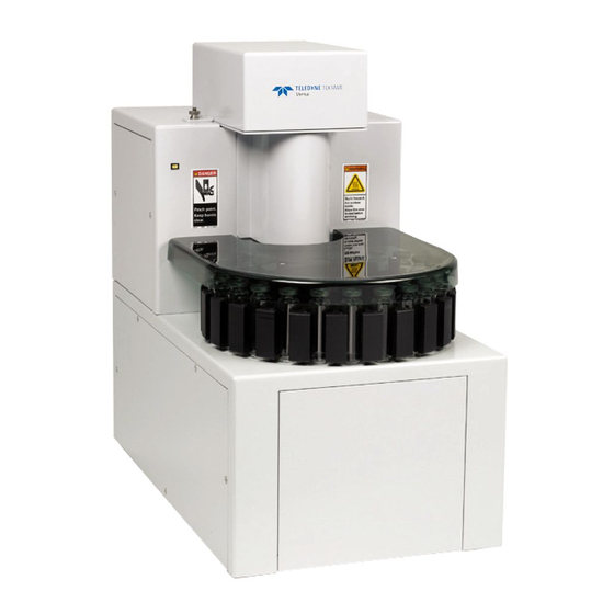
component overview This section describes and illustrates the internal and external parts of the Versa. Figure 1-2: Front of Versa Figure 1-3: Rear of Versa Introduction • Page 1-8 Versa User Manual www.teledynetekmar.com... -
Page 16: Vials
VIals The Versa is designed to accomodate a 22mL Septum glass vial. (Teflon® face down VIal coVer (optIonal) toward vial Sample Vial opening) An optional acrylic vial cover, for protection from hot vials, is available for use with the Versa. pressUre reGUlator The Versa has a pressure regulator located directly inside the plumbing compartment. -
Page 17: Sample Needle
sample needle The Versa uses a 1-stage sample needle to displace sample from the vial to the sample loop. floW restrIctor The Versa uses a 100mL/min flow restrictor to provide Figure 1-8: 1-Stage Needle standby flow and pressurization flow. When the system pressure is set to 18psig, the standby and pressurization flow measured out the needle is approximately 50mL/min. -
Page 18: Headspace Valves
headspace ValVes The Versa system has two solenoid valves in the standard configuration. The standard valves are the Pressurization Valve and the Vent Valve. pressurization Valve The Pressurization Valve allows pressurization gas to flow through the needle to pressurize the vial and sweeps the system between samples. -
Page 19: Versa Mechanisms
Versa mechanIsms Pinch Point Hazard! Keep hands and other appendages away from the carousel and elevator during operation. carousel drive assembly The Carousel Drive Assembly can hold up to 20 vials and stores the vials in accordance with a predetermined Figure 1-15: Carousel Drive Assembly schedule. -
Page 20: Electronic Connections
electronIc connectIons Power Entry Module USB Connection GC/IO Interface Figure 1-17: Rear of Versa power entry module The power entry module is the black component on the right in figure above. There is a switch to turn the unit on and off, a port for a power cord, and a fuse compartment. -
Page 21: Chapter 2: Installation
Chapter 2: Installation & Setup Versa User Manual www.teledynetekmar.com... -
Page 22: Pre-Installation
pre-Installation This section describes: •Prerequisites and site preparation for installation of the Versa •Unpacking and checking the Versa shipment •Major components of the Versa Note: Equipment installation and operation is easier if you use the illustrations and photos to locate and identify the components on the Versa. -
Page 23: Minimum Computer Requirements
• Use good quality pressure regulators with stainless steel diaphragms. The regulators reduce the high source pressures to the Versa. Teledyne Tekmar recommends using a single, two-stage regulator rather than two single-stage pressure regulators to meet the Versa’s pressure specifications. -
Page 24: Required Tools And Supplies For Installation
6. Lift the Versa from the bottom and place it on a bench top. Place the carousel on the unit and locate the star washer and knob from the kit box. Attach and secure carousel to the unit. Notify the Teledyne Tekmar Customer Support Center with any shortage or packing errors immediately: U.s.a.: (800) 874-2004 outside the U.s.a.: Country Code + 1 (513) 229-7000... -
Page 25: Installation
Installation makInG electronIc connectIons power cord 1. Connect the power cord that is included in the packing materials for the Versa to the power entry module on the back right of the unit. 2. Connect the power cord to the wall making sure the wall outlet can supply 5 amps of current for 115 volt units or 2.5 amps of current for 230 volt units. -
Page 26: Making Plumbing Connections
makInG plUmbInG connectIons Inside Line Never connect a flammable gas (such as hydrogen) as the gas supply to the Versa. Venting of this gas in standby creates an explosion hazard. Outside Line pressurize Gas Using the 1/8” blue Teflon® line at the rear of the Versa, labeled “pressurize gas”, connect to a gas supply source and Figure 2-2: Transfer Line secure tightly to prevent any leaks. -
Page 27: Versa Teklink™2G Installation
Versa teklink™2G Installation Your system should have approximately 50 megabytes of free space and a CD-ROM drive or USB. See the Minimum Computer Requirements section for further requirements. 1. Start Windows® and insert your Versa TekLink 2G CD into the drive. All other programs should be shut down during installation. - Page 28 5. Choose the destination directory for the Versa TekLink 2G and click next. The default directory is displayed below: Figure 2-5: Step 5 6. Select the components you want to install, from the drop down menu, and click the next button. The default is displayed below: Figure 2-6: Step 6 7.
- Page 29 8. The next screen that appears allows you to select additional tasks to be performed during the install. If your operating environment requires you to be part 21 CFR Part 11 compliant, select the Enable 21 CFR Part 11 security and auditing button.
- Page 30 2G icon is in the start | all programs | teledyne tekmar | Versa teklink 2G program folder. Also, if you selected the option to place an icon on the desktop, you can double-click the icon to start the program.
- Page 31 12. The next screen that appears asks you to select the host computer. If hosting on this computer, then select “This Computer. ” If hosting from another source then choose it from the dropdown list and click log In. note: There is no username and password needed in order to log in to Versa TekLink 2G unless you have selected the CFR option.
- Page 32 14. Clicking the add button causes the New Instrument Properties screen to appear. From this screen, you must specify a unique name for the instrument and select one of the available ports that the instrument will use for communication. name - The user must enter the name of the active or selected instrument.
-
Page 33: Connecting To The Versa
connecting to the Versa Usb drIVer InstallatIon In order for the Versa to communicate with your PC, you will need to install the drivers for the USB port. At this step, the process will be different depending on which operating system you have on your PC. Follow the steps below that pertain to your PC’s operating system. - Page 34 If you are running Windows Vista or Windows 7: 1. Make sure your Versa unit has been turned on, and navigate to start | control panel | hardware & sound | devices & printers on your PC. Then double-click on the Versa main icon.
-
Page 35: Selecting Your Usb Connection
selectInG yoUr Usb connectIon Now that your USB driver has been installed, and you are connected to the unit you have just set up, you will need to select the correct USB connection by clicking on tools | configuration. 1. Select the USB dropdown menu. 2. -
Page 36: Chapter 3: Basic Operation Basic Operation
Chapter 3: Basic Operation Versa User Manual www.teledynetekmar.com... -
Page 37: Sample Preparation
basic operation sample preparatIon A properly capped and sealed vial is critical in maintaining sample integrity during headspace autosampling. The following are guidelines for proper vial preparation. Figure 3-1: Properly Sealed Vial When a vial is undercrimped, the cap shape will be concave and the cap can be easily rotated. The “tuck-under” on the vial will be at an angle, not in contact with the underside of the collar. -
Page 38: Seal Quality Factors
High quality glass vials may have a tolerance of +/- 0.2mm collar height and the seal may range in thicknesses of 2.5mm to 3.0mm. Teledyne Tekmar recommends that you use an adjustable crimping tool to allow for these variations. Hand or plier-type crimpers accommodate varying seals and vial thicknesses, but require more effort than automatic crimpers, especially when you have multiple vials to crimp at one time. -
Page 39: Prepare Vials For Sampling
prepare Vials for sampling 1. Place the cap on a firm surface. 2. Insert the septum into the cap (avoid contamination of the septum face, the shiny Teflon® face should always be face-down toward the vial). 3. Place the septum and cap together on top of the vial opening. 4. -
Page 40: Spiking Prior To Capping
spiking prior to capping The advantage of spiking a vial prior to capping is that the septum remains uncompromised and the potential for leakage is minimized. When spiking a vial prior to capping, the following precautions should be taken: 1. When spiking into a liquid matrix, be sure to inject the spike below the meniscus of the sample to minimize volatilization of the spiking material to the atmosphere. - Page 41 The analyte mass injected into the vial is determined from the known concentration of standard solutions or the density for pure compounds. The gas volume of the vial is dependent on the vial size. NOTE: Teledyne Tekmar vial volume is 22.3mL (+/- 0.09% RSD). Figure 3-5: Loading a Vial When preparing a vial for analysis by FET consider the following: •...
-
Page 42: Mode Descriptions
mode descriptions The Versa performs a programmed series of operating steps. These steps are referred to as modes and vary depending on type of methodology being completed. Basic mode descriptions are provided below. For more specific descriptions based on your method selection, refer to the valve output charts with mode descriptions. modes mode description... -
Page 43: Valves And Mechanisms
ValVes and mechanIsms mode pressurize Valve Vent Valve 6-port Valve Vial position standby/ready No Vial sample equilibrate No Vial mixing No Vial stabilize No Vial raising Vial to needle Raising Vial to Needle static pressure reading Vial on Needle pressurize Vial on Needle pressure equilibrate Vial on Needle... -
Page 44: Chapter 4: Versa Teklink
Chapter 4: Versa TekLink™2G Versa User Manual www.teledynetekmar.com... -
Page 45: Software Configuration
software configuration Using a personal computer, running Microsoft Windows® XP™ Pro or higher, Versa TekLink™2G enables you to program, monitor, schedule, and control custom operating sequences. Before setting up methods and running samples, familiarize yourself with the Versa TekLink™2G software. To allow for full functionality, the Versa TekLink™2G software must be interfaced with a functional Versa/GC system. -
Page 46: Configuring An Active Instrument
confIGUrInG an actIVe InstrUment To specify the configuration of an active instrument, click tools | configuration. The subsections below describe the contents of the General, and options tabs in the configuration screen. The comments tab contains a text box in which comments can be placed and has no other function. -
Page 47: Voc Teklink Tm 2G Icons And Menus
Voc teklink™2G Icons and menus Situated below the Versa TekLink™2G menu is a bar containing icons. These icons allow you easier access to some of the more commonly used menu items and commands. Figure 4-7: Main Screen Icon Bar fIle menU From the file menu you can access the options for opening, saving, printing, and accessing methods and schedules. -
Page 48: Mode Menu
mode menU From the mode menu, you can access the functions featured below. These commands put the unit in the selected mode, and also give the user the option to perform other functions. Functions available depend on your system configuration. Items that are inaccessible are not relevant to your current configuration. -
Page 49: Method & Schedule Menus
method & schedule menus Do not over pressurize or over heat samples during operation. Extreme static pressure build-up in a vial due to excess pressure levels or heat settings could cause a vial to burst. creatInG and UsInG methods After you have installed and configured the Versa, you can create customized methods &... -
Page 50: Building And Editing Schedules
bUIldInG and edItInG schedUles After creating customized methods, you can define method schedules that specify samples, operating sequences, and the order in which they run. You can build a new schedule using file | new | schedule or by clicking the new button Figure 4-14: File | New | Schedule then selecting schedule from the drop-down menu. -
Page 51: M.o.m. Builder
m.o.m. builder Versa methods can be optimized with the M.O.M. feature. This module allows the user to optimize each parameter in the method to achieve the best possible analytical results. To enter the M.O.M. feature the user must select the button labeled “M.O.M. Builder” from the schedule screen. A pop up window appears to begin the M.O.M. -
Page 52: Schedule Editor
schedule editor An existing schedule can also be edited by clicking file | open | schedule. Browse to the folder where you store your schedules and open the desired schedule. To edit a schedule, click on the line number you wish to change. -
Page 53: Software Features
software features dIaGnostIcs The diagnostics screen can be accessed by clicking tools | diagnostics. In this screen you can run individual diagnostics for specific components. note: The Diagnostics screen is only accessible from Standby or Purge Ready. Use of the Diagnostics screen by untrained users can cause damage to the Versa. -
Page 54: Communications Tab
communications tab The communications tab provides data on system communications between the boards in the Versa and the Versa TekLink™2G. It records signals sent, received, aborted, and retried. benchmark The benchmark screen can be accessed by clicking tools | benchmark. The benchmark screen contains an interactive program that tests the Versa components including the heaters, LEDs, and the continuity of inputs and outputs on the CPU board. -
Page 55: System Properties
The all history log is a filterable log of all the events that have occurred in the system. To adjust the event filter click the link “Click here to adjust the event filter” at the top of the history screen. After choosing the desired filter options, click ok to view the filtered log. -
Page 56: System Properties - E-Mail Tab
system properties - e-mail tab The e-mail tab contains an option to allow the Versa TekLink™2G server to send e-mail alerts. To enable the option, enter the desired server address, appropriate port, account, password, and originating e-mail address in the appropriate text box to set up e-mail alerts. -
Page 57: To Upgrade Versa Firmware
WarnInG! failure to follow this procedure exactly can cause irreversible damage to your equipment! to UpGrade Versa fIrmWare To upgrade the Versa firmware, follow the directions below: 1. Click this hyperlink: Software Downloads (http://www.teledynetekmar.com/resources/downloads/) 2. Under Voc firmware and software, find the appropriate firmware or software upgrade and click on it. -
Page 58: If You Are Running Windows Vista Or Windows 7
If you are running Windows Vista or Windows 7: 1. Navigate to start | control panel | hardware & sound | devices & printers. 2. Double-click on Versa dfU and choose the hardware tab. Then click on properties. Figure 4-37: Versa Main Icon Figure 4-38: Hardware Tab Figure 4-39: Versa Main Properties 3. -
Page 59: Preferences
preferences preferences - General tab The preferences screen contains any miscellaneous options for the software. This option, when selected, will display a save as screen when an existing method or schedule is changed and then saved. preferences - e-mail tab The e-mail tab contains an option to receive e-mail alerts when certain events occur. -
Page 60: Export Feature
export featUre The Versa TekLink™2G offers the exportation of methods and schedules. The following are the steps necessary to export desired information to another source. Once the appropriate screen, Method, Schedule etc. has been selected and you are ready to export, from the tool bar, select file | export. -
Page 61: Chapter 5: 21 Cfr Part 11 Compliance
Chapter 5: 21 CFR Part 11 Compliance Versa User Manual www.teledynetekmar.com... -
Page 62: 21 Cfr Part 11 Features And Compliance Tools
21 CFr Part 11 Features and Compliance tools Versa TekLink™2G is a 21 CFR Part 11 compliance tool. This means that: • User accounts and access privileges are secure. • Methods and schedules are all versioned and archived. • View/Print System, Error, and Sample History Logs. Features: •... -
Page 63: User Manager
User manager The User Manager screen can be accessed by clicking tools | User manager. This screen allows the Administrator and users, with the appropriate permissions, to create user accounts and set up privileges for each account. accounts tab Beneath the name field is the list of all user names created in Versa TekLink™2G. -
Page 64: Permissions Tab
Permissions tab User permissions can be edited by selecting the desired user, accessing the new User Properties screen, and selecting the Permissions tab. Using the option boxes, the user permissions can be individually allowed or disabled. A user that has restricted permissions will either not be able to select the restricted option or will receive a message when they attempt to perform a restricted action. -
Page 65: Edit An Existing Account Permissions
edit an existing account Permissions 1. Select the User Account from the User manager screen. 2. Click the Properties button, then the Permissions tab. The screen should display the current permissions for that user. 3. Select the appropriate boxes. 4. Click oK. Lockout Users can be locked out after a set number of bad logon attempts using the system Properties screen. -
Page 66: Data Versioning, History, And Archive
data Versioning, history, and arChiVe Version – Each method and schedule has a version component built into the file. Anytime that file is changed or modified it will version itself. From the Version tool bar, a drop list shows the latest Version Number with the ability to call the entire list of previous versions. - Page 67 Figure 5-11: History Filter Screen The source drop-down menu displays selections for the source of the event history data (current date or an archive file). The Limit text box displays the amount of events to be displayed. The arrows change the number by 1000 positively or negatively depending on the arrow.
-
Page 68: Change Justification
Change JUstiFiCation Change Justification notices are used anytime a change is made for any reason on any field within the Versa Teklink 2G software if the Change Justification has been selected for that user within their “Preferences” tab. If the need arises to create (add) or delete current Change Justification selections the following steps will guide you through the proper process. - Page 69 You may wish to verify that your task was completed properly. To do so, from the tool bar go to “Tools” and using the pull down menu select “System Properties”. The “System Properties” screen will appear with a “Change Justifications” tab. Scroll through the justifications to insure that the addition or deletion step performed previously has taken place.
-
Page 70: Chapter 6: Method Development
Chapter 6: Method Development Installation & Setup • Page 2-6 Versa User Manual www.teledynetekmar.com... -
Page 71: Optimization Steps For Static Headspace Analysis
oPtimization stePs For statiC headsPaCe anaLysis It is imperative that a rugged analytical method be developed to achieve the best results from the Versa. To complete this task, a thorough understanding of the headspace technique is critical. This section will review: •... -
Page 72: Derivatization
derivatization Another technique that is often used in headspace analysis is derivatization, which can drastically alter the partitioning coefficient by changing the structure of the compound. Compounds on which analysts typically choose to perform this step are alcohols, acids and amines, due to their poor partitioning and the tendency to interact with the sample pathway. -
Page 73: Sample Equilibration
samPLe eqUiLibration Platen/sample temperature One of the factors that has a direct influence on the K value is the platen/sample temperature. Typically, the higher the temperature the lower the K value. As the sample temperature increases, the solubility of the analyte increases, but the vapor pressure also increases. -
Page 74: Universal Gas Law Parameters
UniVersaL gas Law Parameters Since the headspace that is sampled using this technique is a gas, its characteristics are dictated by the Universal Gas Law, PV=nRT where P is Pressure, V is Volume, n is Number of Moles or Mass, R is a constant and T is temperature. In headspace analysis “n”... -
Page 75: Loop Fill Pressure
Loop size Volume is controlled by the size of the loop selected. The standard loop that is shipped with the unit is 1mL. Teledyne Tekmar offers loops from 0.1mL to 5mL. The larger the loop, the more sample gas is transferred on column. It should be noted that before deciding to use a larger loop, due to the increased sensitivity, all other optimizations should be exhausted. -
Page 76: System Pressure And Standby Flow
There are two critical factors that need to be known to properly set the inject time, the GC carrier flow rate and the loop size. Teledyne Tekmar recommends that a minimum volume of three times the loop size should be flushed through the sample loop during inject to completely transfer the sample gas to the GC. -
Page 77: Chapter 7: Maintenance & Troubleshooting
Chapter 7: Maintenance & Troubleshooting Versa User Manual www.teledynetekmar.com... -
Page 78: Service Contact Information
Contact information If any parts are missing, if you wish to order replacement parts, need technical support, or want an instrument serviced, call the Teledyne Tekmar Customer Support Center at the number below: U.s.a.: (800) 874-2004 outside the U.s.a.: Country Code + 1 (513) 229-7000... -
Page 79: To Upgrade Versa Firmware
warning! Failure to follow this procedure exactly can cause irreversible damage to your equipment! to UPgrade Versa Firmware To upgrade the Versa firmware, follow the directions below: 1. Click this hyperlink: Software Downloads (http://www.teledynetekmar.com/resources/downloads/) 2. Under VoC Firmware and software, find the appropriate firmware or software upgrade and click on it. -
Page 80: If You Are Running Windows Vista Or Windows 7
if you are running windows Vista or windows 7: 1. Navigate to start | Control Panel | hardware & sound | devices & Printers. 2. Double-click on Versa dFU and choose the hardware tab. Then click on Properties. Figure 7-8: Versa Main Icon Figure 7-9: Hardware Tab Figure 7-10: Versa Main Properties 3. -
Page 81: Setting/Checking Versa System Pressure
The preventative maintenance schedule (below) lists procedures that can be performed without the assistance of a Teledyne Tekmar service representative. The more familiar you become with these procedures, the less time it will take to complete them. -
Page 82: Monthly Maintenance Checks
monthly maintenance Checks • Perform daily and weekly Checks • Check system Pressure - Perform Set System Pressure in software by going to tools | set system Pressure. • run a benchmark test – This is a diagnostic test used to check the outputs of the Versa. From the Versa TekLink™2G toolbar, select tools | benchmark. -
Page 83: Troubleshooting
4. Call Teledyne Tekmar: teledyne tekmar Customer support Center: U.s.a. and Canada: (800) 874-2004 or tekmarsupport@teledyne.com outside the U.s.a.: Country Code + 1 (513) 229-7000 or tekmar_intltech@teledyne.com Maintenance & Troubleshooting • Page 7-6 Versa User Manual www.teledynetekmar.com... -
Page 84: System Will Not Power Up
Try a different power Reset the receptacle. Do not use breaker. an extension cord! Does unit have power? Call Teledyne Finished Tekmar Customer Service Center 800-874-2004 Maintenance & Troubleshooting • Page 7-7 Versa User Manual www.teledynetekmar.com... -
Page 85: Printed Circuit Boards
The interior of the instrument is an electrical shock hazard. Turn off the instrument and unplug the power cord before removing the protective covers. Printed CirCUit boards Versa operations are controlled by five printed circuit boards and two power supplies. temperature Control board The Temperature Board is on the bottom of the chassis on the right-hand side. -
Page 86: Carousel Motor Board
Carousel motor board The Carousel Board is located on the carousel mechanism and can be seen from the front of the instrument. The Carousel Board is responsible for for the carousel motor, optical sensor and othe boards. The switch setting should be set to position “one. -
Page 87: Heater Failures
Heater will be disabled until the unit is rebooted. Please power down the unit and check electrical connections, confirm the heater resistance and confirm fuse. If the problem persists contact Teledyne Tekmar’s Technical Support for troubleshooting advice. runaway oven, Platen, or transfer Line The following error will appear in Versa TekLink™2G when there is a runaway Oven, Platen, or Transfer Line Heater(s):... - Page 88 adjust the Carousel sensor (if necessary) Adjust the Carousel Sensor if the slots of the carousel are not centered with the slot on the chassis. CAUTION: This should be performed by a trained service engineer due to electrical shock hazard. 1.
-
Page 89: How To Align The Sample/Elevator Mixer Assembly
Versa do not return the Versa unless a Teledyne Tekmar representative authorizes you to do so. A service representative may be able to help you solve the problem over the telephone. If the instrument must be returned, the representative can tell you how to prevent damage during shipment. -
Page 90: Chapter 8: Diagrams
Chapter 8: Diagrams Versa User Manual www.teledynetekmar.com... -
Page 91: Detailed Plumbing
Detailed Plumbing Diagrams • Page 8-2 Versa User Manual www.teledynetekmar.com... -
Page 92: Standby/Ready, Sample Equilibrate, Mixing, And Stabilize
standby/ready, sample equilibrate, mixing, and stabilize Diagrams • Page 8-3 Versa User Manual www.teledynetekmar.com... -
Page 93: Raising Vial To Needle
raising Vial to needle Diagrams • Page 8-4 Versa User Manual www.teledynetekmar.com... -
Page 94: Static Vial Pressure Reading
static Vial Pressure reading Diagrams • Page 8-5 Versa User Manual www.teledynetekmar.com... -
Page 95: Pressurize
Pressurize Diagrams • Page 8-6 Versa User Manual www.teledynetekmar.com... -
Page 96: Pressure Equilibrate, Vial Pressure Reading
Pressure equilibrate, Vial Pressure reading Diagrams • Page 8-7 Versa User Manual www.teledynetekmar.com... -
Page 97: Loop Fill, Loop Fill Pressure Reading
Loop Fill, Loop Fill Pressure reading Diagrams • Page 8-8 Versa User Manual www.teledynetekmar.com... -
Page 98: Inject
inject Diagrams • Page 8-9 Versa User Manual www.teledynetekmar.com... -
Page 99: Electrical Schematic
Electrical Schematic Diagrams • Page 8-10 Versa User Manual www.teledynetekmar.com... - Page 100 Chapter 9: Index Versa User Manual www.teledynetekmar.com...
- Page 101 nUmeriCs 21 CFR Part 11 Features and Compliance Tools ... 5-2 Daily Maintenance Checks ..........7-4 6-Port Valve ................1-11 Data Versioning, History, and Archive ......5-6 Derivatization ................6-3 Detailed Plumbing Diagram ..........8-2 Accounts Tab ................5-3 Diagnostics ................4-10 Additional Headspace References ........
- Page 102 Leak Check ................7-1 pH ....................6-2 Location Selection ..............2-1 Partition Coefficient............... 1-5 Lockout ..................5-5 Permissions Tab ............... 5-4 Loop Fill, Loop Fill Pressure Reading Diagram ..... 8-8 Phase Ratio ................6-3 Loop Fill Pressure ..............6-6 Platen ..................1-11 Loop Size ...................
- Page 103 Heater Failures ..............7-10 Low Response Loop ............7-9 Salting Out ..................6-2 Master Board ..............7-8 Sample/Elevator Mixer Assembly ........1-12 Pressure Transducer Board ......... 7-9 Sample Equilibration ............. 1-4, 6-4 Printed Circuit Boards ........... 7-8 Sample Needle ............... 1-10 Temperature Control Board........7-8 Sample Loop ................1-9 Sample Preparation ..............3-2 Sample Preparation Method Development ....6-2...
Need help?
Do you have a question about the Tekmar Versa and is the answer not in the manual?
Questions and answers