
Related Manuals for powersoft DigiMod PFC2


Summary of Contents for powersoft DigiMod PFC2
- Page 1 DigiMod PFC2 - PFC4 Service Manual ©2018 Powersoft Keep this manual powersoft_DigiModPFC2.PFC4_servman_en_v2.3 for future reference...
- Page 2 Intentionally left blank...
-
Page 3: Table Of Contents
INTERNAL CAPACITORS BANK BEFORE HANDLING THE DEVICE Checking the Control Board’s LEDs Checking the Rail’s Voltages This technical document aims to be a support guide in repairing and low-voltage testing the DigiMod PFC2 and PFC4 power Checking the Auxiliary Voltage amplifiers. Checking the Control Board... -
Page 4: Testing Equipment
DigiMod PFC2 - PFC4 | SERVICE MANUAL 1. Testing Equipment: DigiMod PFC DigiMod PFC PSU VOLTAGE AUX CABLE DC CABLE +30 V from the power supply To Pin 2 of +15 V from the To the Module... -
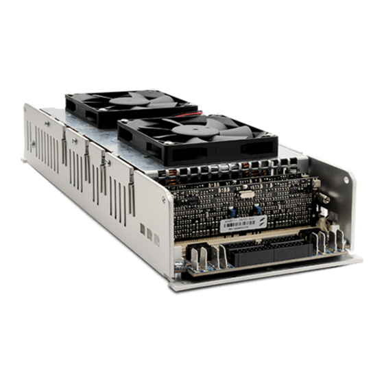
Page 5: Opening The Module's Cover
DigiMod PFC2 - PFC4 | SERVICE MANUAL 2. Opening the Module’s Cover: DigiMod PFC2 With a Phillips Head Screwdriver, remove all 4 screws indicated on (Fig. 1). Lift the top cover and unplug the fan’s power cable. (Fig. 1) DigiMod PFC4 With a Phillips Head Screwdriver, remove all 6 screws indicated on (Fig. -
Page 6: Discharging The Capacitor's Bank
DigiMod PFC2 - PFC4 | SERVICE MANUAL 3. Discharging the Capacitor’s Bank: DigiMod PFC2 Connect the ends of a 60W light bulb to the points marked on (Fig. 3) (Fig. 3) DigiMod PFC4 Connect the ends of a 60W light bulb... -
Page 7: Main Board Layout
DigiMod PFC2 - PFC4 | SERVICE MANUAL 4. Main Board Layout: DigiMod PFC4 DigiMod PFC2 AC EMI FILTER AC EMI FILTER VOLTAGE VOLTAGE CH 1-2 CNTRL CH 1-2 CNTRL CH 3-4 CNTRL Remove Jumper to switch gain to 38 dB... -
Page 8: Troubleshooting
DigiMod PFC2 - PFC4 | SERVICE MANUAL 5. Troubleshooting: Checking the fuse and varistor Ω Ω This step is common to both PFC2 and PFC4 models. With a multimeter se to Ohm, check for continuity in the F1 fuse and for 270 KΩ on the VR1 Varistor as portrayed on (Fig. -
Page 9: Checking The Power Supply
DigiMod PFC2 - PFC4 | SERVICE MANUAL DigiMod PFC4 By means of a multimeter set to Ohm, check for any short Ω Ω circuit in the Mosfets by probing on the points indicated on (Fig. 9). Please refer to the following table when ordering the repair Kit. -
Page 10: Amp Stage Current Consumption
DigiMod PFC2 - PFC4 | SERVICE MANUAL Amp stage current consumption 30 V 80mA 30 V 80mA Make sure that the Control Board is properly inserted in the Module. Connect the Banana Plugs of the DigiMod PFC AUX Voltage Cable to the power supply as portrayed on (Fig. -
Page 11: Checking The Pfc Converter
DigiMod PFC2 - PFC4 | SERVICE MANUAL Checking the PFC converter This step is common to both PFC2 and PFC4 models. 15Vdc 27.5mA By means of the DigiMod PSU AUX Voltage Cable, connect a DC Power supply to the module’s PL1 connector and supply 15Vdc. -
Page 12: Switching The Module On In Dc
DigiMod PFC2 - PFC4 | SERVICE MANUAL Switching the module on in DC This step is common to both the PFC2 and PFC4 models. 15Vdc 17.5mA 30Vdc 375mA By means of the DigiMod PSU AUX Voltage Cable, connect a DC Power supply to the module’s PL1 connector and supply 15Vdc. -
Page 13: Checking Modules In Dc - Psu Current Consumption
DigiMod PFC2 - PFC4 | SERVICE MANUAL Checking modules in DC - PSU Current Consumption Connect two external power supplies as portrayed in the 30 V 98 mA 30 V 98 mA pictures in order to switch on the module with 120 V Check the Current Consumption on the Power Supply. -
Page 14: Checking The Control Board's Leds
DigiMod PFC2 - PFC4 | SERVICE MANUAL Checking the Control Board’s LEDs The following applies to both the PFC2 and PFC4 models. Leave both power supplies on as for the previous test (120 Vdc) and check the control board’s LEDs by referencing the table portrayed on (Fig. -
Page 15: Checking The Auxiliary Voltage
DigiMod PFC2 - PFC4 | SERVICE MANUAL Check of the auxiliary voltage In order to check the AUX Voltages, leave both power supplies on as for the previous test (120 Vdc) and probe on the indicated points with a multimeter. -
Page 16: Checking The Output Stage Mosfets
DigiMod PFC2 - PFC4 | SERVICE MANUAL Checking the Output Stage Mosfets: DigiMod PFC2 Switch the module on in DC, with an oscilloscope check the waveforms on the points highlighted in the figure below. 134Vp 192 134Vp 192 12.5Vp 192... - Page 17 DigiMod PFC2 - PFC4 | SERVICE MANUAL DigiMod PFC4 Switch the module on in DC, with an oscilloscope check the waveforms on the points highlighted in the figure below. 134Vp 192 134Vp 192 12.5Vp 192 12.5Vp 192...
- Page 18 DigiMod PFC2 - PFC4 | SERVICE MANUAL 134Vp 192 134Vp 192 12.5Vp 192 12.5Vp 192 Please refer to the following table when ordering the repair Kit. Model Kit Number Description DigiMod PFC2 KT000891.R KIT DM PFC2 AMP 1CH DigiMod PFC4 KT000841.R...
-
Page 19: Checking The Output Stage
Checking the output stage - NO LOAD CONNECTED Connect the module to the KT000291 Interface Board (CH1/2 on DigiMod PFC2, CH1/2 - CH3/4 on DigiMod PFC4) , and press the switches between the XLR connectors in order to link CH1+CH2 and CH3+CH4. -
Page 20: Output Current Offset Calibration Procedure
Output Current Offset Calibration Procedure - NO LOAD CONNECTED Connect the module to the KT000291 Interface Board (CH1/2 on DigiMod PFC2, CH1/2 - CH3/4 on DigiMod PFC4) , and press the switches between the XLR connectors in order to link CH1+CH2 and CH3+CH4. -
Page 21: Kt000291 Interface Board
DigiMod PFC2 - PFC4 | SERVICE MANUAL KT000291 Interface Board Link switches Single channel Mode SW1/2 Link CH1 + CH2 Single channel Mode SW3/4 Link CH3 + CH4 Input connectors CH 1 CH 3 CH 4 CH 2 CB000350 Testing point... - Page 22 DigiMod PFC2 - PFC4 | SERVICE MANUAL Connect the module to the KT000291 Interface Board (CH1/2 on DigiMod PFC2, CH1/2 - CH3/4 on DigiMod PFC4) , and press the switches between the XLR connectors in order to link CH1+CH2 and CH3+CH4.
-
Page 23: Adjusting The Level Of The Input Signal
DigiMod PFC2 - PFC4 | SERVICE MANUAL Plug the Service Load AT000043 to the CH1 Faston Connectors Plug a DC Power Supply to the Service Load by means of the CB000419 cable, slowly increase the voltage to 24V 24Vdc 220mA... -
Page 24: Thermal Limit
DigiMod PFC2 - PFC4 | SERVICE MANUAL Thermal Limit Switch the input signal off. Switch the module on. Measure the voltage at the TEMPMON pin 2.75 V < V < 2.85 V (no input signal) TEMPMON Switch the input signal on. -
Page 25: Testing The Rails Volt Voltage
DigiMod PFC2 - PFC4 | SERVICE MANUAL Testing the rails Volt Voltage Measure the voltage at the +VCCMON and –VCCMON pin: input signal switched off 2.80 V < | V | < 2.90 V peak VCCMON peak input signal switched on 7.20 V... -
Page 26: Main Board Disassembly
DigiMod PFC2 - PFC4 | SERVICE MANUAL 6. Main Board Disassembly: DigiMod PFC2 Using a M5 Socketed Wrench, remove the screw highlighted on (Fig. 24). Carefully remove all 4 springs indicated on (Fig. 5). Highlighted on the figure below are all 10 screws needed to be unscrewed in order to remove the main board from the chassis. -
Page 27: Digimod Pfc4
DigiMod PFC2 - PFC4 | SERVICE MANUAL DigiMod PFC4 Using a M5 Socketed Wrench, remove the screw highlighted on (Fig. 25). Carefully remove all 8 springs indicated on (Fig. 25). Highlighted on the figure below are all 14 screws needed to be unscrewed in order to remove the main board from the chassis. -
Page 28: Replacing The Sil Pads
DigiMod PFC2 - PFC4 | SERVICE MANUAL 7. Replacing the Sil Pads: Before replacing the Sil Pads, remove ALL the old ones from both the Main PCB and the chassis. Clean any residue of dust and glue. Apply the Sil Pads in the appropriate position according to the pictures below. - Page 29 DigiMod PFC2 - PFC4 | SERVICE MANUAL DigiMod PFC4 DigiMod PFC2, PFC4 Silpad HI-FLOW 625 40X55 Reassemble the unit by tightening all Phillips Head Screws, the Socketed Screw on the side of the chassis and by properly resetting all tension springs.
-
Page 30: Dsp Fw Installation Procedure
DigiMod PFC2 - PFC4 | SERVICE MANUAL 8. DSP FW installation procedure (DSP-D only): Once the repairing procedure is over, reset the DSP Preset DSP Version Firmware Version board by upgrading the FW. Tens Units DigiMod comes with two types of DSP boards: DSP-C 1.2.0... -
Page 31: Firmware Upgrade Via Digimod Pfc Manager
DigiMod PFC2 - PFC4 | SERVICE MANUAL 9. Firmware Upgrade Via DigiMod PFC Manager: The following procedure is designed to be implemented when servicing modules derived from Ottocanali HGT (Disney) Amps. • Insert the SM000886 DigiMod Programmer Board in the DSP Slot. - Page 32 DigiMod PFC2 - PFC4 | SERVICE MANUAL Upgrading the EEPROM • Click on “Tools” • Click on “Enable” • insert the password: “ p@ssw0rd ” • Click on the indicated point “Load File” • Double-Click the EEPROM Upgrade file i.e. EEPROM_2004PFC4_rev 3.hex •...
-
Page 33: Repair Kit List
DigiMod PFC2 - PFC4 | SERVICE MANUAL 10. Repair Kits List: Model Kit Number Description KT000890.R KIT DM PFC2 PSU DigiMod PFC2 KT000891.R KIT DM PFC2 AMP 1CH KT000843.R KIT DM PFC4 PSU DigiMod PFC4 KT000841.R KIT DM PFC4 AMP 1CH KT000843.R... - Page 34 DigiMod PFC2 - PFC4 | SERVICE MANUAL Final test report Module ON Powersoft DigiMod 3004 PFC4 EIAJ input signal Powersoft DigiMod 3004 PFC2 Service Without (1 kHz 3 V 8-32 cycle) Load Signal With Output max Limiter (8sec ) SERIAL NUMBER:...
- Page 35 DigiMod PFC2 - PFC4 | SERVICE MANUAL IMPORTANT SAFETY ADDENDUM The aim of this addendum is to describe the safety precautions to be undertaken when servicing any Powersoft amplifier/module. WE RECOMMEND THAT ALL SERVICE OPERATIONS ARE CARRIED OUT BY A TRAINED TECHNICIAN IF NOT EXPLICITLY STATED OTHERWISE, DISCONNECT THE AMPLIFIER FROM THE MAINS.
- Page 36 Intentionally left blank...
- Page 37 Tel: +39 055 735 0230 Fax: +39 055 735 6235 General inquiries: info@powersoft.it Sales: sales@powersoft.it Application & technical support: support@powersoft.it Service & maintenance: service@powersoft.it powersoft-audio.com Data are subject to change without notice. For latest update please refer to the online version available on www.powersoft-audio.com...
Need help?
Do you have a question about the DigiMod PFC2 and is the answer not in the manual?
Questions and answers