
Subscribe to Our Youtube Channel
Related Manuals for powersoft Digam K20


Summary of Contents for powersoft Digam K20
- Page 1 K20 - K10 - K8 - K6 - K4 - K3 Digital Audio Amplifier for Professional Applications User Manual V1.15 (15-5-2009)
- Page 2 This page left intentionally blank...
-
Page 3: Table Of Contents
Table of contents Important safety instructions ..........................2 Approvals ................................3 Warning Notices................................3 Safety rules..................................4 Speaker damage................................4 Speaker output shock hazard............................5 ntroduction ..................................6 More sound and less weight.............................6 Superior Sound-Sonic Accuracy............................6 Totally Digital with High Reliability................................6 The Best amplifier for Your Mains................................6 The K Series......................................6 The Show Always Goes On..............................6 Chapter 1: Installation and operation... -
Page 4: Important Safety Instructions
CAUTION Important safety instructions RISK OF ELECTRIC SHOCK DO NOT OPEN CAUTION: TO REDUCE THE RISK OF ELECTRIC SHOCK, DO NOT REMOVE THE COVER. NO USER- SERVICEABLE PARTS INSIDE. REFER SERVICING TO QUALIFIED SERVICE PERSONNEL. "WARNING: TO REDUCE THE RISK OF FIRE OR ELECTRIC SHOCK, DO NOT EXPOSE THIS APPARATUS TO RAIN OR MOISTURE AND OBJECTS FILLED WITH LIQUIDS, SUCH AS VASES, SHOULD NOT BE PLACED ON THIS APPARATUS"... -
Page 5: Approvals
Approvals The Digam K series is installed according to the Canadian Electrical Code or National Electrical Code, as applicable. Install this product in accordance with Canadian Electrical Code or National Electrical Code and other local electrical or building codes as applicable. Mount in rack only. The flexible mains cable must not pass through walls K10 - K8 - K6 - K4 This equipment has been tested and found to compliant by Competent Body (Directive 89/336/EEC-EMC) pursuant to the... -
Page 6: Safety Rules
It is the user's responsibility to use suitable speakers with the amplifier and to use them in a sensible way that will not cause damage. Powersoft will not be responsible for damaged speakers. Consult the speaker manufacturer for power-handling recommendations. Even if you reduce the gain using the amplifier's front panel attenuation controls, it is still possible to reach full output power if the input signal level is high enough. -
Page 7: Speaker Output Shock Hazard
A DIGAM amplifier is capable of producing hazardous output voltages. To avoid electrical shock, do not touch any exposed speaker wiring while the amplifier is operating. This manual contains important information on operating your DIGAM amplifier correctly and safely. Please read it carefully before operating your amplifier. If you have any questions, contact your Powersoft dealer. -
Page 8: Introduction
Introduction Powersoft is a leading company in the field of high efficiency audio power management. The totally new Powersoft's DIGAM (DIGital AMplifier) technology has changed the way the world looks at professional audio amplification. No other amplifiers come close for applications demanding high power and long term reliability. Thanks to amazing... -
Page 9: Chapter 1: Installation And Operation
Every Powersoft amplifier is completely tested and inspected before leaving the factory and should arrive in perfect condition. If you find any damage, notify the shipping company immediately. Be sure to save the carton and all packing materials for the carrier's inspection. -
Page 10: Mounting
1.2 Mounting All DIGAM amplifiers are previewed for the standard 19" rack mounting; there are four front panels holes and fout rear lateral holes. The amplifiers must be fixed into rack in both sides, back and frontal, to avoid mechanical damages. Your DIGAM amplifier uses a forced-air cooling system to maintain a low, even operating temperature. -
Page 11: Connecting Inputs
1.5 Connecting Inputs . Input connections are made via the 3-pin XLR-female type or 1/4" phone Jack connectors on the rear side of the amplifier. The polarity is shown in figure 1.5.1. pin2 - IN(+) OUT2 LINK ON OFF OUT1 pin1 - GND pin3 - IN(-) IN(-) -
Page 12: Connecting Outputs
1.6 Connecting Outputs Warning: there are lethal voltages at the loudspeaker connectors when the amplifier is turned on. To prevent any damages turn the amplifier off before connecting the loudspeaker Output connectors are made via neutrik speakon connectors. Consult the wire gauge chart to find a suitable wire gauge to minimize power and damping factor losses in the speaker cables. -
Page 13: Connecting Remote Control
1.7 Connecting Remote Control You can control the amplifier via a RS485. The figure 1.7.1 shows the connection of the data cable to the plug located to the rear panel of the amplifier connection. The same figure shows also the ID selection for Remote Control (in this case ID= 28);... -
Page 14: Aux Input Ch1/Ch2
1.8 AUX Input CH1/CH2 (K2I and K3I only) These inputs are automatically selected in place of the line input CH1/CH2 when an external voltage of 24V DC is applied through the AUX COMMAND input, these inputs can be used for emergency signals as pre-recorded evacuation messages or similar alarm messages. -
Page 15: Chapter 2: Setup And Settings
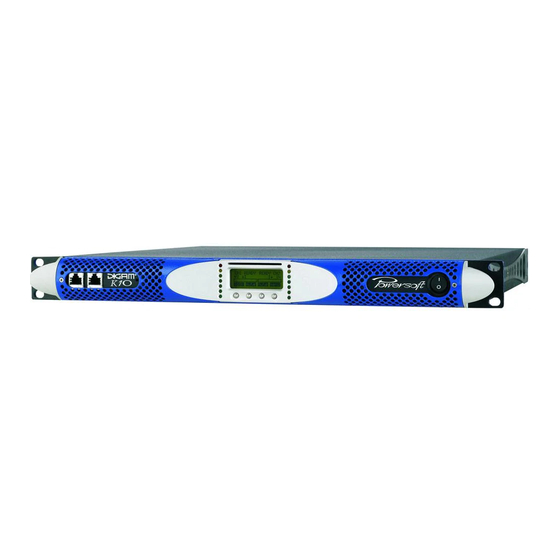
2 Setup and settings 2.1 Introduction The figure below shows the front panel of DIGAM K Series. The front panel controls, in conjuction with the graphic LCD display above the buttons, give to the user the total control and detailed information about the status of the amplifier. -
Page 16: The Main Menu
The fourth line of the screen shows the functions of the buttons below. The "lock" function is activated if the corresponding button is pressed more than 1 second; in this case all the other buttons are locked. The same operation unlocks these buttons (unlock code is required - see par. 2.3.17 for more details). The "mute"... -
Page 17: Output Attenuation
To better handle the huge amount of parameters, the single value numeric input mode is extended with a fine/coarse feature. When you edit one of the parameters, you will start in the “fine” mode. The steps applied by the - and + keys are the minimum allowable for that parameter. -
Page 18: Input Select
2.3.3 Input select You can choose among three different input modes (if available): Analog, Digital AS3* with or without DSP processing and Ethernet**. The up and down buttons change the selection; the "sel" button locks the selected option. * Available only with optional DSP board ** Available only with optional KAESOPboard 2.3.4 Max output voltage The figure 2.3.7 shows the Max output voltage screen. -
Page 19: Gate Ch1-Ch2
2.3.7 Gate CH1 - CH2 This function allows to mute the amplifier channels individually if input signal amplitude is falling below the values shown in the following table. You can enable/disable it by pushing the on/off button. Gating the output is delayed by 5 seconds after input signal removal, and follows in reversed way the bottom green LED on the CH1, CH2 bar LED display *(muted if green LED is off). -
Page 20: Temperature
2.3.14 Temperature In the Temperature screen you can view the historic temperature diagram of the last four hours of the final current use in the range from 10 to 90°C; in the bottom-right side of the screen there is the present value (see figure 2.3.10). 38°C back figure 2.3.10... -
Page 21: Hardware Info
Note that if you have already input a preset name, or if you have loaded a preset from local memory or smartcard, the name is kept by the amplifier and used as starting point for a new save preset operation. For example, suppose that you have loaded a preset named “18IN SUB 1”... -
Page 22: Lcd Contrast
2.3.20 LCD contrast In this screen you can set the contrast of the LCD display by pushing the +/- buttons (see figure 2.3.19). Contrast back figure 2.3.19 2.3.21 Set keylock code In this screen you can insert the numeric key to unlock the settings; the same screen appears when the "unlock" button in the main screen is pressed. -
Page 23: The Smartcard Function
2.3.24 The Smartcard function There is the possibility to store up to 150 presets for each settings smartcard (shown figure 2.3.21) . The menu is activated when the smartcard is inserted in the amplifier, only if the main page of the menu is selected. The store and recall procedures are identical to those used for local presetsas shown in figure 2.3.22. -
Page 24: Chapter 3: Protection
3 Protection 3.1 Turn-On/Turn-Off muting For about four seconds after turn-on, and immediately at turn-off, the amplifier outputs are muted. 3.2 Short circuit protection A short circuit protection system safeguards the amplifier's output transistors under short circuits and other stressful loads. It is completely inaudible when inactive. -
Page 25: Chapter 4: User Maintenance
There are no user-serviceable parts in your DIGAM amplifier. Refer servicing to qualified technical personnel. In addition to having an in-house service department, Powersoft supports a network of authorized service centers. If your DIGAM amplifier needs repair, contact your Powersoft dealer or distributor, or contact the Powersoft Technical Service... -
Page 26: Chapter 5: Warranty
5 Warranty Powersoft prides itself on the quality and reliability of its products that are designed and manufactured to meet the highest quality standards. We are also proud of the great care we assure to our customers. We are confident that you will never have a need to take advantage of this warranty, but in the unlikely event of a failure or deviation in performance, we'll do our very best to get you swiftly back in business. -
Page 27: Block Diagram
7.2 Block diagram The figure 7.1.1 shows the the output stage block diagram, the figure 7.1.2 shows the power supply block diagram. ETHERNET POWER RAIL CONNECTION BUS +/- DC DETECTOR FUSES SHUTDOWN OPTION TO POWER OUTPUT OUTPUT MAX SUPPLY ATTENUATOR VOLTAGE SELECTOR PATH OUTPUT CH1... -
Page 28: Technical Specifications
7.3 Technical specifications POWER REQUIREMENTS Power supply..........................115÷230V(-15%, +15%) Power factor................more than 0.95 (0.90 for K3 - K2) from 500W to full power Operating temperature ........……………...……..............0° C, 45° C Weight....................8Kg (17.6 lbs) for K3 - K2, 12Kg (26.5 lbs) all others External dimensions.........Standard rack 19"... - Page 29 7.4 Maximum output voltage settings for maximum output power limitation Maximum output voltage settings for maximum output power limitation Maximum peak output voltage settings for output power limitation on the most common load impedances Maximum peak Output power W @ load Output power W @ load Maximum peak output voltage...
- Page 30 This page left intentionally blank...
- Page 31 Powersoft s.r.l. - P. IVA n° 04644200489 - Via E. Conti, 5 Scandicci - Tel.: (+39) 0557350230 - Fax: 0557356235...
Need help?
Do you have a question about the Digam K20 and is the answer not in the manual?
Questions and answers