Table of Contents
Advertisement
Quick Links
Download this manual
See also:
User Manual
Advertisement
Table of Contents

Subscribe to Our Youtube Channel
Related Manuals for powersoft DigiMod 3004PFC2


Summary of Contents for powersoft DigiMod 3004PFC2
-
Page 1: User Manual
DigiMod 3004PFC2 user manual rev. 1.1 © 2012 - 2013 Powersoft Keep This Manual For Future Reference powersoft_dm3004PFC2_uguide_en_v0.1... - Page 2 Page intentionally left blank...
-
Page 3: Table Of Contents
DigiMod 3004PFC2 User Manual Table of contents 1 Welcome 11 Audio path block diagram 2 Unpacking & checking for shipping damage 12 Internal signal path polarity 3 Disposal of the packing material 13 Protections 13.1 Power supply protections 4 Important safety instructions 13.2 Amplifier protections... - Page 4 Page intentionally left blank...
-
Page 5: Welcome
4 � per channel (2000 W on 8 � in mono-bridged mode), the Rather than just throwing these materials away, please ensure DigiMod 3004PFC2 reaches a new level of excellence in terms of they are offered for recycling. power consumption and sonic performance. -
Page 6: Important Safety Instructions
Ensure a proper ventilation. the IEC 364 or similar rules. Is absolutely necessary to verify this f Install in accordance with Powersoft’s instructions. fundamental requirement of safety and, in case of doubt, require f Do not install near any heat sources or apparatus that an accurate check by a qualified personal. -
Page 7: Fire And Liquids
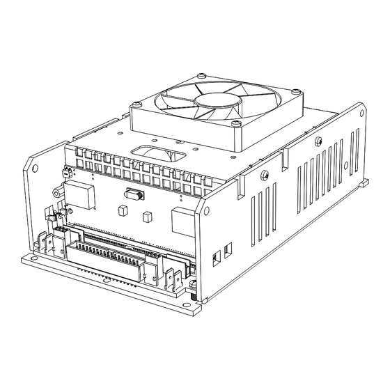
Do not obstruct air ow Cooling of the DigiMod 3004PFC2 is achieved by means of the built-in fan cooler which shall be improved by assembling to the module’s chassy a proper external passive heat sink. The built-in fan cooler (80x80 mm, 24 V... -
Page 8: Mechanical Drawing
202,9 202,9 140,2 140,2 98,7 98,7 M3 THREADED M3 THREADED HOLE HOLE Ø4.2 THROUGH HOLE Ø4.2 THROUGH HOLE 48,9 48,9 N°10 POS. N°10 POS. N°5 POS. N°5 POS. 12,2 12,2 FIGURE 2: DigiMod 3004PFC2 mechanical drawings. All dimensions in millimiters. -
Page 9: Main Connections
6.3 x 0.8 mm 6.3 x 0.8 mm Channel 1 Channel 1 Mono Mono Bridge Bridge Channel 2 Channel 2 FIGURE 3: DigiMod 3004PFC2 – AC MAINS and audio output wiring. Parallel Parallel Channel 1 COLD COLD COLD COLD input input... -
Page 10: Surface Components Layout
9 Surface components layout 9.1 Bill of connectors CODE NAME TYPE DSP/external circuit board socket 72-pin SIMM Socket PL21 Input connector IDC flat cable 34 ways Test Connector (reserved) IDC flat cable 20 ways PL17 Signal OUT 1 + Faston 6.3x0.8 mm Male PL18 Signal OUT 1 –... -
Page 11: Main Connectors Pinout
SIMM specifications, please contact and PL13 connectors. By means of these jumpers it is possible to Powersoft. SIMM board pinout is shown on FIGURE 7. change the main gain and enable the DSP and external circuits. -
Page 12: Pl21 Pinout
10.3 PL21 pinout Pin# Name Type Description Range Scale Factor Impedance Power supply shut down. Active SDPWS 3,3V < V <12V 1KΩ High. Enable enegy save mode Channel 1 PWM state. High when 3,3V < V <5V 47KΩ - external cap. READY 1 output 1 PWM generation is <... - Page 13 ...continued from previous page. Pin# Name Type Description Range Scale Factor Impedance Channel 2 hardware mute. Active MUTE 2 low. Disable output stage PWM VIL (max)=0,2V | Isink=20mA (min) generator OUT POWER Regulated -12V supply output (for -12V (+/-5%) Max current= see pin 14 audio circuits) OUT POWER Regulated +12V supply output (for...
-
Page 14: Audio Path Block Diagram
11 Audio path block diagram IN 2 + IN 2 + IN 1 + IN 1 + 47 Ohm 47 Ohm 470p 470p IN 2 – IN 2 – IN 1 – IN 1 – 47 Ohm 47 Ohm 470p 470p BY12 BY11... -
Page 15: Protections
Amplifier protections are triggered by audio signal current and of scaling or critical changes in environmental conditions. voltage – by comparing input and output – and NTC, negative The architecture of Powersoft’s amplifiers encompass temperature coefficient, thermistors. NTC thermistors provide several protection mechanisms triggered by harmful signal and thermal feedback to the Control Board, to the Main Board and temperature. -
Page 16: Harmful Signal Protections
The Main Board and the Control Board microcontrollers work When a high frequency stationary loud signals is feed into the in parallel by triggering fan speed rotation and output power amplifier the Control Board limits its mean current depending on modulation at different temperature threshold. -
Page 17: Led Chart
14 LED chart Both the Main Board and the Control Board are equiped with status LED and protection LED; refer to FIGURE 10 and FIGURE 11 for LED localization and the following table for LED description. 14.1 Control Board LED chart LED ID Type Description... -
Page 18: Service
(the form is an editable tab guided document) and save as authorized service centers. If your amplifier needs repair contact your name, amp model and serial number (for example: your Powersoft dealer (or distributor). You can also contact the distributorname-DM3004PFC2-17345.doc) providing... -
Page 19: Specifications
DSP & Networking (optional board) Connector 72-pin SIMM socket (DSP-D and DSP- 4 compatible) + IDC32P (Compatible with DSP-Lite) Configuration Fully supported within Powersoft Armonía Pro Audio Control Suite Construction Dimensions 216 mm x 122 mm x 79 mm (8.5” x 4.8” x 3.1") Weight 1550 g (3.4 lb) - Page 20 Via Enrico Conti, 5 50018 Scandicci (FI) Italy Tel: +39 055 735 0230 Fax: +39 055 735 6235 General inquiries: info@powersoft.it Sales: sales@powersoft.it Application & technical support: support@powersoft.it Service & maintenance: service@powersoft.it www.powersoft-audio.com © 2012 - 2013 Powersoft powersoft_dm3004PFC2_uguide_en_v0.1...
Need help?
Do you have a question about the DigiMod 3004PFC2 and is the answer not in the manual?
Questions and answers