powersoft DigiMod 3004PFC4 User Manual
Hide thumbs
Also See for DigiMod 3004PFC4:
- Quick manual (2 pages) ,
- User manual (41 pages) ,
- User manual (33 pages)

Related Manuals for powersoft DigiMod 3004PFC4


Summary of Contents for powersoft DigiMod 3004PFC4
-
Page 1: User Manual
DigiMod 3004PFC4 user manual rev. 1.1 © 2012 - 2013 Powersoft Keep This Manual For Future Reference powersoft_dm3004PFC4_uguide_en_v1.1... - Page 2 Page intentionally left blank...
-
Page 3: Table Of Contents
DigiMod 3004PFC4 User Manual 10 Audio path block diagram Table of contents 11 Internal Signal Path Polarity 1 Welcome 12 Protections 2 Unpacking & checking for shipping damage 12.1 Power supply protections 3 Disposal of the packing material 12.2 Amplifier protections 12.3 Harmful signal protections... - Page 4 Page intentionally left blank...
-
Page 5: Welcome
4 � per channel (2000 W on 8 � in mono-bridged mode), the normally be recycled. DigiMod 3004PFC4 reaches a new level of excellence in terms of Rather than just throwing these materials away, please ensure power consumption and sonic performance. -
Page 6: Important Safety Instructions
Ensure a proper ventilation. the IEC 364 or similar rules. Is absolutely necessary to verify this f Install in accordance with Powersoft’s instructions. fundamental requirement of safety and, in case of doubt, require f Do not install near any heat sources or apparatus that an accurate check by a qualified personal. -
Page 7: Fire And Liquids
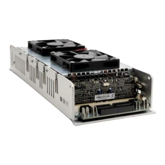
Do not obstruct air ow reliable operation. Cooling of the DigiMod 3004PFC4 is achieved by means of the built-in fans cooler which shall be improved by assembling to the module’s chassy a proper external passive heat sink. The two built-in fans cooler (80x80 mm, 24 V... -
Page 8: Mechanical Drawing
7 Mechanical Drawing 108.4 54.2 13.1 29.2 M3 THREADED HOLE N°14 POS. Ø 4.2 THROUGH HOLE 81.1 N°5 POS. FIGURE 2: DigiMod 3004PFC4 mechanical drawing. All dimensions in millimeters. -
Page 9: Main Connections
Channel 2 Channel 1 6.3 x 0.8 mm Bridge 3-4 FIGURE 3: DigiMod 3004PFC4 – AC MAINS and audio output wiring: Channel 4 Channel 3 a. Four ways – four single channels; b. Three ways – channels 3-4 in bridge mode;... -
Page 10: Main Connectors Pinout
COLD Channel 2 COLD Channel 4 FIGURE 4: DigiMod 3004PFC4 – four input channels wiring. FIGURE 5: DigiMod 3004PFC4 – parallel input wiring. 9 Main connectors pinout 9.1 Bill of connectors The following image and tables show the pinout of main... - Page 11 FIGURE 7: DigiMod 3004PFC4 surface components layout.
-
Page 12: Pl1003 Pinout
9.2 PL1003 pinout Scale Imped- Tolle- PIN# Name POWER Range Protected Description factor ance rance Logic input Active High, SDPWS 1 k� to be fed by Power Supply Shut Down Logic input 3.3 to 12 V “OR” diode RESERVED RESERVED RESERVED Ground Unbalanced... - Page 13 ...continued from previous page. Scale Imped- Tolle- PIN# Name POWER Range Protected Description factor ance rance -VCCMON –7.5 V 4.5 k� Rail Bus Positive Monitor +VCCMON +7.5 V 4.5 k� Rail Bus Negative Monitor Active Low, CH1 and CH2 To be pulled to GND by MUTE Output Stage Mute current sink of at least...
-
Page 14: Pl3003 Pinout
9.3 PL3003 pinout Scale Imped- Tolle- PIN# Name POWER Range Protected Description factor ance rance Logic input Active High, SDPWS 1 k� to be fed by Power Supply Shut Down Logic input 3.3 to 12 V “OR” diode RESERVED RESERVED RESERVED Ground Unbalanced... - Page 15 ...continued from previous page. Scale Imped- Tolle- PIN# Name POWER Range Protected Description factor ance rance -VCCMON –7.5 V 4.5 k� Rail Bus Positive Monitor +VCCMON +7.5 V 4.5 k� Rail Bus Negative Monitor Active Low, CH3 and CH4 To be pulled to GND by MUTE Output Stage Mute current sink of at least...
-
Page 16: Pl1000 Pinout
9.4 PL1000 Pinout 9.6 PL3000 Pinout Pin# Name Impedance Description Pin# Name Impedance Description Channle 1 Channle 3 BY31 2.7 k� + 47 � BY31 2.7 k� + 47 � Unbalanced Intput Unbalanced Intput 32dB gain 32dB gain 2.7 k� + 47� 2.7 k�... -
Page 17: Audio Path Block Diagram
10 Audio path block diagram IN 2 + IN 2 + IN 1 + IN 1 + 47 Ohm 47 Ohm 470p 470p IN 2 – IN 2 – IN 1 – IN 1 – 47 Ohm 47 Ohm 470p 470p BY12 BY11... -
Page 18: Protections
Amplifier protections are triggered by audio signal current and of scaling or critical changes in environmental conditions. voltage – by comparing input and output – and NTC, negative The architecture of Powersoft’s amplifiers encompass temperature coefficient, thermistors. NTC thermistors provide several protection mechanisms triggered by harmful signal and thermal feedback to the Control Board, to the Main Board and temperature. -
Page 19: Harmful Signal Protections
The Main Board and the Control Board microcontrollers work When a high frequency stationary loud signals is feed into the in parallel by triggering fan speed rotation and output power amplifier the Control Board limits its mean current depending on modulation at different temperature threshold. -
Page 20: Led Chart
13 LED chart Both the Main Board and the Control Board are equiped with status LED and protection LED; refer to FIGURE 11 and FIGURE 12 for LED localization and the following table for LED description. 13.1 Control Board LED chart LED ID Type Description... -
Page 21: Service
All warranty repairs and retrofits must be performed at in a waterproof transparent envelope so it is clearly visible. Powersoft facilities or at an Authorized Service Center at no cost for the purchaser. Warranty exclusion: Powersoft’s warranty does All returning items must be shipped to the following address:... -
Page 22: Specifications
72-pin SIMM socket (DSP-C and DSP- 4 compatible) Configuration Configurable with SigmaStudio or predefined layout Remote control Fully supported by Powersoft Armonía Pro Audio Control Suite Construction Dimensions 309 mm x 122 mm x 79 mm (12” x 4.8” x 3.1”) Weight 2400 g (5.3 lb) - Page 23 Page intentionally left blank...
- Page 24 Via Enrico Conti, 5 50018 Scandicci (FI) Italy Tel: +39 055 735 0230 Fax: +39 055 735 6235 General inquiries: info@powersoft.it Sales: sales@powersoft.it Application & technical support: support@powersoft.it Service & maintenance: service@powersoft.it www.powersoft-audio.com © 2012 - 2013 Powersoft powersoft_dm3004PFC4_uguide_en_v1.1...
Need help?
Do you have a question about the DigiMod 3004PFC4 and is the answer not in the manual?
Questions and answers