
Related Manuals for powersoft Digimod Series


Summary of Contents for powersoft Digimod Series
- Page 1 Digimod DigiMod 500 DigiMod 1000 DigiMod 1500 DigiMod 2000HV DigiMod 1000 NPS Service Manual ©2016 Powersoft Keep this manual powersoft_DigiMod500.1000.1500.2000HV.1000NPS_servman_en_v2.3 for future reference...
- Page 2 Intentionally left blank...
-
Page 3: Table Of Contents
The components to be replaced are clearly shown to help their identification. At the end of this guide you can find a detailed list with the description and the respective Powersoft internal reference code of the spare parts. Always use an anti-static wrist band while servicing the amplifier. -
Page 4: Testing Components Kit
DigiMod 500 1000 1500 2000HV 1000NPS | SERVICE MANUAL DigiMod 500 1000 1500 2000HV 1000NPS | SERVICE MANUAL 1. Testing Components Kit: DigiMod AMP AUX Voltage Cable DigiMod Mains DC Cable PSU AUX Voltage Cable Lamp (min.40W/230V, best 60W/230V) for discharging the amplifier’s capacitors bank DigiMod Mains Cable... -
Page 5: Opening The Module's Cover
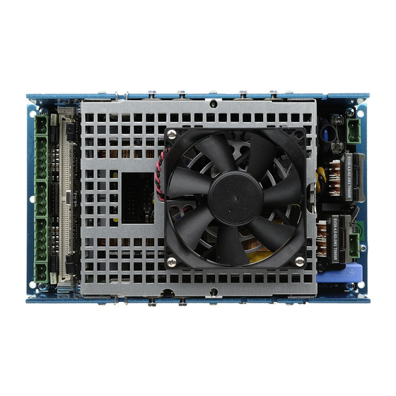
DigiMod 500 1000 1500 2000HV 1000NPS | SERVICE MANUAL 2. Opening the Module’s cover: Remove the Control Board by unscrewing the two steel spacers with a M5 socketed wrench and un-clipping the retainers highlighted in (Fig. 1) (Fig. 1) Locate and unscrew all 6 Phillips Head Screws holding the module’s cover, 3 per side. -
Page 6: Discharging The Module's Capacitors Bank
DigiMod 500 1000 1500 2000HV 1000NPS | SERVICE MANUAL 3. Discharging the Capacitor’s Bank: Connect one side of a 60W light bulb to the pins marked (+) and the other side to a ground point, repeat on the other side of the CN13 connector. (Fig. -
Page 7: Troubleshooting
DigiMod 500 1000 1500 2000HV 1000NPS | SERVICE MANUAL 5. Troubleshooting: Ω Ω Checking the Output Mosfets: DigiMod 500 | 1000 | 1500 | 2000HV Check for any short in the Output Mosfets by probing with a multimeter set to Ohm between the points highlighted in (Fig. -
Page 8: Checking The R10 Ntc
DigiMod 500 1000 1500 2000HV 1000NPS | SERVICE MANUAL Checking the R10 NTC: Ω With the Multimeter set to Ohm, check for continuity in the R10 NTC, by probing the points highlighted in (Fig. 8). (Fig. 8) Checking the RV1 Varistor: Ω... -
Page 9: Main Pcb Disassembly
DigiMod 500 1000 1500 2000HV 1000NPS | SERVICE MANUAL 6. Main PCB Disassembly: DigiMod 500 | 1000 | 1500 | 2000HV Using a M5 Socketed Wrench, and a regular M5 Wrench, remove all 9 screws and nuts highlighted in the pictures below. Proceed by removing the retainer spring holding the Zobel resistor in place. -
Page 10: Digimod 1000Nps
DigiMod 500 1000 1500 2000HV 1000NPS | SERVICE MANUAL DigiMod 1000NPS Using a M5 Socketed Wrench, and a regular M5 Wrench, remove all 4 screws and nuts highlighted in the pictures below. Proceed by removing the retainer spring holding the Zobel resistor in place. The image below portrays all 7 screws needed to be removed in order to separate the PCB from its casing. -
Page 11: Dc Voltage Testing
DigiMod 500 1000 1500 2000HV 1000NPS | SERVICE MANUAL 7. DC Voltage Testing: Connect a DC Power Supply to the CN4 connector by means of PSU AUX VOLTAGE CABLE. (Fig. 11) Slowly increase the voltage to +18V, and verify the consumption, it should be as stated in the following table. - Page 12 DigiMod 500 1000 1500 2000HV 1000NPS | SERVICE MANUAL By means of the PSU AUX VOLTAGE CABLE, supply +18Vdc to the module through the CN4 connector. With an oscilloscope, check if the waveforms on the IGBTs pins are as portrayed in the picture below. 18Vdc 20mA...
- Page 13 DigiMod 500 1000 1500 2000HV 1000NPS | SERVICE MANUAL Connect a DC Power supply to the CN4 connector by means of the PSU AUX VOLTAGE CABLE, and supply +18 Vdc. By means of the DIGIMOD AMP AUX VOLTAGE CABLE, connect a second power supply and set the output voltage to ± 15Vdc, and check the absorption: it should be as portrayed in the table below.
- Page 14 DigiMod 500 1000 1500 2000HV 1000NPS | SERVICE MANUAL By means of the DIGIMOD AMP AUX VOLTAGE CABLE, connect a DC power supply and set the output voltage to ± 15Vdc. Check the shape of the waveforms by first probing on the 2, 4 pins of the U15 IC, then check the shape of the waveforms by probing on pins 6, 8.
- Page 15 DigiMod 500 1000 1500 2000HV 1000NPS | SERVICE MANUAL By means of the DIGIMOD AMP AUX VOLTAGE CABLE, connect a DC power supply and set the output voltage to ± 15Vdc. Check the shape of the waveforms by probing the highlighted pins on the Q3, Q4, Q5, Q6 Mosfets. The waveforms should be shaped as portrayed in the figure below.
- Page 16 DigiMod 500 1000 1500 2000HV 1000NPS | SERVICE MANUAL By means of the DIGIMOD PSU VOLTAGE CABLE, connect a DC power supply to the CN4 connector and set the output voltage to 18Vdc. By means of the DIGIMOD MAIN DC CABLE, connect a second DC power supply and slowly supply +30Vdc to the module.
- Page 17 DigiMod 500 1000 1500 2000HV 1000NPS | SERVICE MANUAL By means of the DIGIMOD AMP AUX VOLTAGE CABLE, connect a DC power supply and set the output voltage to ± 15Vdc. Check the AUX voltages by probing on the highlighted points in the CN14 connector. Alternatively it is possible to check the Aux Voltages while the board is removed from its chassis by checking the voltage regulators on the back side of the board, as indicated on (Fig.
- Page 18 DigiMod 500 1000 1500 2000HV 1000NPS | SERVICE MANUAL By means of the DIGIMOD AMP AUX VOLTAGE CABLE, connect a DC power supply and set the output voltage to ± 15Vdc. (Fig. 13) +15Vdc -15Vdc (Fig. 13) Check the Control board by measuring its oscillator’s clock signal, it should be 12MHz.
-
Page 19: Output Current Offset Calibration Procedure
Connect a function generator or a cd player to the module through the CN12, CN11 connectors. Select an audio track from the Powersoft Test CD, or a Sine wave test tone. Verify the presence of audio signal by probing on the CN7, CN3 connectors with an oscilloscope. -
Page 20: Silpad Replacement Procedure
DigiMod 500 1000 1500 2000HV 1000NPS | SERVICE MANUAL 9. SIlpad Replacement Procedure Once the repair procedure has been ultimated, replace all silpads. Remove any residue of dirt, glue or dust that might have been trapped in the module. The following images portray where to place the IS000040 Silpad. IS000040 ULTRASOFT 18x30 mm IS000031 HI-FLOW 40x55 mm DigiMod 1000NPS... -
Page 21: Fw Installation Procedure
DigiMod 500 1000 1500 2000HV 1000NPS | SERVICE MANUAL 10. DSP FW installation procedure: Once the repairing procedure is over, reset the DSP Preset DSP Version Firmware Version board by upgrading the FW. Tens Units DigiMod comes with two types of DSP boards: DSP-C 1.2.0 DSP-C (Black PCB, 4 Micro Match) -
Page 22: Repair Kit List
DigiMod 500 1000 1500 2000HV 1000NPS | SERVICE MANUAL 11. Repair Kit List: Model Kit Number Description Part Number Description KT000818.R KIT DM500 PSU IS000031 HI-FLOW 40x55 mm KT000819.R KIT DM500 AMP 1CH IS000040 ULTRASOFT 18x30 mm KT000820.R KIT DM1000 PSU ML000009 WIRE SPRING 1.2mm cod. -
Page 23: Fake/Unauthorized Copies
Those fake modules’s chassis is Golden/Yellow instead of being either Black, Light Blue or Gray. Powersoft Authorized Service Centres are NOT authorized to repair these modules. Never use our kits or components in order to repair those unauthorized copies. - Page 24 DigiMod 500 1000 1500 2000HV 1000NPS | SERVICE MANUAL IMPORTANT SAFETY ADDENDUM The aim of this addendum is to describe the safety precautions to be undertaken when servicing any Powersoft amplifier/module. WE RECOMMEND THAT ALL SERVICE OPERATIONS ARE CARRIED OUT BY A TRAINED TECHNICIAN IF NOT EXPLICITLY STATED OTHERWISE, DISCONNECT THE AMPLIFIER FROM THE MAINS.
- Page 25 Intentionally left blank...
- Page 26 Tel: +39 055 735 0230 Fax: +39 055 735 6235 General inquiries: info@powersoft.it Sales: sales@powersoft.it Application & technical support: support@powersoft.it Service & maintenance: service@powersoft.it powersoft-audio.com Data are subject to change without notice. For latest update please refer to the online version available on www.powersoft-audio.com...
Need help?
Do you have a question about the Digimod Series and is the answer not in the manual?
Questions and answers