Advertisement
Table of Contents
- 1 Troubleshooting
- 2 Power Cord Configurations
- 3 Service Precautions
- 4 Part Description
- 5 Rear Panel
- 6 Replacing the Fans
- 7 Removing the Power Supply
- 8 SD Card Removal
- 9 Fan Failure
- 10 Dante Controller
- 11 Final Checklist
- 12 Replacement Parts
- 13 Appendix A: X Series Front Panel
- 14 Connect the Device
- 15 Output Channel
- 16 Safety Precautions
- Download this manual
Advertisement
Table of Contents

Related Manuals for powersoft X4


Summary of Contents for powersoft X4
- Page 1 X4 Amplifier Platform Service Manual ©2018 Powersoft Keep this manual powersoft_X4_servman_en_v2.5 for future reference...
- Page 2 Intentionally left blank...
- Page 3 X4 | SERVICE MANUAL X4 Service Manual Structure Safety Information Index Equipment Requirement Power Cord Configurations Service Precautions Note on Soldering Note on Replacing Parts 5.2.1 Explaination significato label Amplifier Serial Number 5.2.2 Mac Address Description of The Amplifer External 6.1.1...
- Page 4 Replacement Parts Appendix A: X Series Front Panel Important Safety Addendum X4 Service Analysis & Troubleshooting Structure Analysis and Solution Digi / ADLink Hardware To analysis HW problem on digi/adlink, first of all unmount it following the instruction on Chap. 7.11 of this guide.
-
Page 5: Troubleshooting
X4 | SERVICE MANUAL Troubleshooting SYMPTOM AREA SYMPTOM POSSIBLE CAUSES CHECK ACTIONS AUDIO No Audio Digi / ADLink HW Check Components Swap Golden Sample Digi / ADLink FW Update FW (or Recovery Card) Flat Cables Swap Golden Sample AMP Module... - Page 6 Fan Failure identification. At the end of this guide you can find a detailed Firmware Issue list with the description and the respective Powersoft internal reference code of the spare parts. Power Spply Verification Procedure Always use an anti-static wrist band while servicing the amplifier.
-
Page 7: Power Cord Configurations
5.2 Note on REPLACING PARTS About the AMP Module The amplifier module of this unit is able to correspond to repairing in the component manufacturer (Powersoft Company). And it holds charge-free warranty period for 16 months after production. 5.2.1 Serial Number Label The Serial Label is pasted also in the amplifier module itself, and makes clear the production year and month. -
Page 8: Part Description
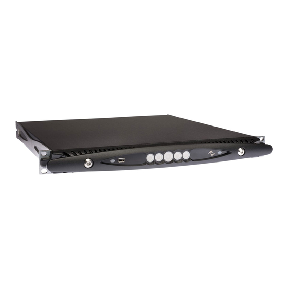
X4 | SERVICE MANUAL 6. Part Description 6.1 External Amplifier Front Amplifier Rear 6.1.1 LED Configurations and Meanings FW Version 1.8.7.16 RING LED CENTRE LED LED STATUSES SOLID LED is On BLINKING LED alternates from solid on to solid off... - Page 9 X4 | SERVICE MANUAL Solid WHITE Ring LED - CHANNEL: Input signal detected Solid ORANGE Centre Channel LED: Muted Channel Ring LED OFF: Input signal off (-60 dBu). Dimmed Solid WHITE Ring LED: Input signal detected (from -57 dBu). Solid WHITE Ring LED: Input signal detected (up to 25 dBu).
- Page 10 X4 | SERVICE MANUAL Front LED illuminated buttons Armonía callback In order to indentify the unit into the Armonía Workspace, push on the rightmost button. On the other hand, if you click on Un/ Main on/off switch MUTE ALL Blink from the contextual menu of the amplifier into the Armonía Workspace, all the front LEDs of the amplifier will blink for a while.
-
Page 11: Rear Panel
X4 | SERVICE MANUAL Pulsing YELLOW Centre LED: Power supply temp. > 70° Pulsing RED Ring LED (10 sec.): AMP Fan is faulty Pulsing RED Centre LED (10 sec.): PSU Fan is faulty Solid ON YELLOW Centre LED: User Limiter - Set by the user Pulsing YELLOW Centre LED: CH Thermal Protection ON (70°) - Page 12 X4 | SERVICE MANUAL 6.2.1 Main Module Locations Colour Description Wi-Fi Module AMP Module Power Supply Module X Front Slot Ethernet Board DIGI/ADLINK Boards EMI Filter 6.2.2 PSU Components Colour Description AUX CIRCUITS CLOCK VARISTORS CAPACITORS BANK TRANSFORMERS...
- Page 13 X4 | SERVICE MANUAL 7. Disassembling Instruction 7.1 Removing the Front Panel Remove the front panel by unscrewing the two highlighted Hex screws with a 6 mm Hex Screwdriver. (Fig. 1) (Fig. 1) Remove the filter and soak it in a mild soap and cold water solution, rinse it and let it dry thoroughly.
-
Page 14: Replacing The Fans
BOTH FANS MUST BE MOUNTED WITH THE LABEL FACING OUTWARDS!!! NOTE! If found any fans in the old type of Fan Brackets, please order the KIT FANS X4 SERIES REPLACEMENT to replace the x2 Fans & change the x2 Brackets to the type on the right. - Page 15 X4 | SERVICE MANUAL 7.6 Removing the Varistors In order to replace the Varistors, remove the two screws highlighted on (Fig 10), and lift the varistor bank from its original position. (Fig. 10) 7.7 Removing the EMI Filter By means of a T10 Torx Screwdriver, unscrew the 2 screws highlighted on (Fig.
-
Page 16: Removing The Power Supply
X4 | SERVICE MANUAL 7.8 Removing the Power Supply Remove the EMI Filter. Unscrew the 4 Phillips Head Screws highlighted on (Fig. 14). (Fig. 14) Unplug the Fan’s cables and the Flat cables. By means of an M7 Socketed Screwdriver, remove the nut holding the Power Supply in place. - Page 17 X4 | SERVICE MANUAL 7.9 Removing the Slot Ethernet Board By means of a Torx T10 Screwdriver, remove the two screws highlighted on (Fig. 17). Gently pull the Slot Ethernet Board outwards, removing it from its slot. (Fig. 17) 7.10 Removing the Dante Board...
- Page 18 X4 | SERVICE MANUAL 7.11.1 DIGI Board with Old Memory Chip DIGI BOARD (OLD Chip) 7.11.2 DIGI Board with New Memory Chip DIGI BOARD (NEW Chip) Older productions feature the Brooklyn II board. This picture shows the default configuration of the jumpers The CM0 and CM1 dip switches must be on the “ON”...
- Page 19 X4 | SERVICE MANUAL 7.12 Replacing the Flat Cable Phillips head screws to be removed in order to semparate the DIGI/ADLINK board assembly. Connect the CB000522.01 flat cables to the uppermost connectors Connect the CB000523.01 flat cables to the remaining uppermost connectors and the CB000524.01 flat cables to the lowermost connectors...
-
Page 20: Sd Card Removal
X4 | SERVICE MANUAL When reassembling, arranged the flat cables properly thru the guide slot on the DIGI/ADLINK boards assembly. (Fig. 22) (Fig. 22) When resetting the PSU Flat cables, follow the sequence portrayed on the right. Bend the flat cable as indicated and connect it to the micromatch connector portrayed in the picture. - Page 21 X4 | SERVICE MANUAL 7.14 Removing of Rear Panel 7.14.1 Rear Panel (Old Version) The Old Version Rear Panel (ME000843.00) 7.14.2 Rear Panel (New Version) The New Version Rear Panel (ME001319.R) is removeable from Base (ME001273.R)
- Page 22 X4 | SERVICE MANUAL 8. Symptoms & Faults Visible from Front LED Configuration 8.1 On Audio Modules Thermal Limiter / Limiter issues Solid ON YELLOW Centre LED: User Limiter - Set by the user Pulsing YELLOW Centre LED: CH Thermal Protection ON (70°) Unplug the Unit’s Input and Output Connectors...
- Page 23 X4 | SERVICE MANUAL Thermal Limiter ON Pulsing YELLOW Centre LED: Power Supply temp. > 70° 8.3 On Auxiliary Voltage Alarm at power up Cause: +15V Stby voltage missing or lower than 13.5 V Check: Power supply leds condition (Stand alone)
-
Page 24: Fan Failure
X4 | SERVICE MANUAL Cause: +18Vdc Auxliary missing or lower than +16 Vdc Check: Power supply leds condition (Stand alone) Cause: -18Vdc Auxliary missing or lower than -16 Vdc Check: Power supply leds condition (Stand alone) Cause: Rail voltage +VCC < 40Vdc Check: Power supply leds condition (Stand alone) Cause: Rail voltage -VCC >... - Page 25 X4 | SERVICE MANUAL 8.5 Firmware Issue FW Version prior to 1.7.6.30 Solid ON BLUE Centre and Ring LED (Old FW Version): Firmware is not installed // ADLink or DIGI Boards Problem Latest FW Version Swiping ORANGE Ring and Centre LEDs (all - Latest FW Version): Firmware is not installed // ADLink or DIGI Boards Problem...
- Page 26 X4 | SERVICE MANUAL 9. Power Supply Verification Procedure Disconnect the flat cables from the Power Supply Module. 30 Vdc 250mA 30 Vdc Referring to the diagram below, connect a Power Supply to the module as portrayed on (Fig. 24).
- Page 27 X4 | SERVICE MANUAL Remove the Varistor assembly. Ω With a MultiMeter set to OHM, check the resistance between the two points indicated on (Fig. 25) R= 0Ω: short circuit, replace PSU R= 1K: OK, resume testing procedures. (Fig. 25) Focusing the attention on U29 and U27, as portrayed on (Fig.
- Page 28 X4 | SERVICE MANUAL 10. Amp Modules Verification Each Audio Module features 10 check LEDs, as highlighted on (Fig. 30). In normal conditions, only the 4 Green LEDs are on. In case of malfunction, the Red LEDs will indicate that the module is in protection mode and replacement is necessary.
-
Page 29: Dante Controller
X4 | SERVICE MANUAL 11. Dante Controller & Updater 11.1 Brief Intro about Dante Dante is the de facto standard digital media networking solution, using standard IP infrastructure to network devices, and making interoperability easy and reliable. It distributes uncompressed, multi-channel digital media via standard Ethernet networks, with near- zero latency and perfect synchronization. - Page 30 X4 | SERVICE MANUAL 11.3. Updating Firmware - Initialize Dante Board Use the ‘Home’ tab to update your Dante devices. Click the arrow icons to expand and collapse the sections. Updates Available The Updates Available section of the Home tab lists devices that have been discovered on your Dante network which are eligible for a firmware update (devices for which there is new firmware available in the Dante Updater database).
- Page 31 X4 | SERVICE MANUAL 11.4 About Failsafe 11.4.1 What is failsafe mode? All Dante hardware modules use software loaded from Flash memory as part of their operation. As with any storage device, it is possible to corrupt the data on the Flash part, potentially rendering it unusable, if there are interruptions while writing to the Flash device.
- Page 32 X4 | SERVICE MANUAL 11.5 Using Failsafe Recovery Basic Steps To recover Dante devices in safe mode: 1. Ensure the computer running Dante Firmware Update Manager and the device you wish to recover are on the same IP subnet. (follow instruction n chapter 11.6 from point 1 to 13) 2.
- Page 33 X4 | SERVICE MANUAL Screen 2- Finding devices for safe recovery This screen indicates that Firmware Update Manager has detected at least device in safe mode, and is scanning the network for the full list. It should take less than a minute to find all applicable devices.
- Page 34 X4 | SERVICE MANUAL 11.6 Dante Dynamic IP Restore 1. Download the last version of Dante controller (or at least 4.06.xx version) and install it on your PC (the download is available on https://www.audinate.com/products/software/dante-controller) 2. Execute Dante Controller on your PC 3.
- Page 35 X4 | SERVICE MANUAL 5. Take note about the IP address set on the device (ex. 169.254.200.121) 6. Close Dante controller 7. On your PC enter Control Panel. 8. Open “Network and sharing center” 9. Click on “Change adapter setting”...
- Page 36 X4 | SERVICE MANUAL 12. Select TCP/IPv4 and click on properties. The following windows will be shown 13. Take note of your original configuration and then configure your computer’s network interface with a static IP address in the same range as the IP address for the Dante device. Use the same values for the first three octets and choose a different number from 1 to 255 for the last octet (in this example Dante IP address is 169.254.200.121 , then choose 169.254.200.1 for your PC IP address).
- Page 37 X4 | SERVICE MANUAL 12. Updating of the Firmware using ArmoniaPlus v1.2 On the bottom of the Armonia Workspace panel, click on “Match” & on the top panel, click on “Discovery” in order to load the unit. This procedure may take up to 5 seconds.
- Page 38 To select the Source, Double click on ”FILE” row This window will be shown. Select the image File (different for X4 and X8) from the folder that you have saved on you PC (Recovery Procedure/Recovery SD Card/FW/X4/SD-image-x4-1.8.6.128 (for X4 amplifier) or Recovery Procedure/Recovery...
- Page 39 X4 | SERVICE MANUAL This window will be shown. Click on “Continue” Now select the Target (the micro SD card insert in your PC formatted FAT32) and click to Continue Wait till the end of copying procedure. Now you SD recovery Card is Ready.
- Page 40 14.1 Setting the Serial Number and MAC Address Place the files “update_plain.sh” and “update-X4.bin” in case of an X4 amplifier or files “update_plain.sh” and “update-X8.bin” in case of an X8 amplifier (from the folder you have copied on your PC: Recovery Procedure/Model setting) in a FAT32 Formatted USB Pen Drive (4,8,16 GB max).
- Page 41 X4 | SERVICE MANUAL Insert the Mac Address number, this may be found on the DIGI Board: Note: all serial numbers comprise 8 digits and quotation marks, for example: “12345678” Warning: the first 6 digits of the Mac address (highlighted in red) should never be changed! Click on “save”...
- Page 42 The log file will be named: log.csv The Event file will be named events.csv (Fig. 32) Attach this files to an e-mail and send it to service@powersoft.it (Fig. 33) 16. Extracting the Log Files via SD Card With the amplifier turned off, remove the SD Card and place it in an sd card adaptor.
- Page 43 X4 | SERVICE MANUAL 18. Testing the Unit via ArmonìaPlus Connect the unit to a pc via one of the Ethernet slots as portrayed on (Fig. 34) GREEN led ON (flashing) Link/Activity indicator: Blinking – There is activity on this port.
- Page 44 X4 | SERVICE MANUAL Click on Apply, and click on OK Click on “Match” and click on “Discovery” The Unit and its Serial Number should appear within 5 seconds By hover the mouse cursor on top of the unit’s icon, it is possible to check the Model, Serial, Retel(IP Address), Firmware Drag and drop the unit into the Workshop, notice the ‘white/red...
-
Page 45: Final Checklist
X4 | SERVICE MANUAL Once the Discovery Phase is complete (10 seconds) the square Apply a 1KHz 1Vpp audio signal to CH1 will turn Green. Double click on the Unit to continue the test. Check for presence of the signal in all the other channel’s VMeters... - Page 46 Right Click on the Virtual AMP, Select “PAM” then Click on “Ex- Import a Virtual AMP from the Model List. port” to create & Save a Default X4 Dante.pam File at the Desktop Right Click on the Repaired AMP, Select “PAM” then Click on Click “Yes”...
-
Page 47: Replacement Parts
X4 | SERVICE MANUAL 21. Replacement Parts PART NUMBER DESCRIPTIONS X4/STD/EMIFILTER/12 SMC01012.R +MECCANI TEST +Silc+PCK (EMI FILTER Ver 1) X4/STD/EMIFILTER/12 SMC01012.V2.R +MECCANI TEST +Silc+PCK (EMI FILTER Ver 2) X4/STD/ALI/12 +TEST + SMD01009.R HSINK TEST +Silc+PCK (PSU MODULE) X4: X/STD/AMIN/14 SMD01062.V2.R... - Page 48 X4 | SERVICE MANUAL X/STD/SLOT ETH/12 FOR SM000948.R REPAIR (SLOT ETHERNET BOARD) MODULO WiFi PC000167 802.11abgn - USB A (Wi-Fi BOARD) Mini PCI Module PC000172 BrooklynII 32Tx+32Rx Audio Channels (DANTE BOARD) X4/STD/RAILS/10 FOR SM000944.R REPAIR (RAILS BOARD) X4/STD/VARISTOR PCB X SM001011.R...
- Page 49 X4 | SERVICE MANUAL X SERIES MAINS CN000480 CONNECTOR (INTERNAL) KT000854.R KIT X4 Flat cable replacement CB000527.02 X4 FRONT FLAT CABLE CB000390 X8 CON. SPEAKON ME001234.00 X4 VERS. 2.0 TOP COVER ME001273.03 X4 2.0-BASE ASSEMBLY ME001319.01 X4 2.0 REAR ASSEMBLY...
- Page 50 X4 | SERVICE MANUAL ME001228.02 X4 - 2.0 - FRONT PLATE ME000822.01 X4 SIDE RACK HARNESS ME000832.01 X4 FAN BRACKET ME000856.01 X4 PWS REAR CONNECTOR IS000064.01 X4 AMP, TOP SHIELD - MACROFOL IS000069.00 X4 FRONT RAIL SHIELD FOR PCBA IS000094.02 X4 2.0 PSU LOWER...
- Page 51 X4 | SERVICE MANUAL ET000824.00 X4 2.0 BIADHESIVE FOR FI000027.00 X4 FRONT AIR FILTER ME001117 MAGNET NEODIMIO CSN13 D13 H4,5mm NU000055 FERRITE CORE EMI 22x6.35x13.5 VI000022 SPC_M3x15_FF_HEX_ SW5_NK_PLTD_BR_N_ VI000100 SPC_M3X17_FF_HEX_ SW5_N_ VI000220 SPC_M3x30_FF_HEX_ SW5_NK_PLTD_BR_N_ VI000224 SCW_TSPTX_M3x20_ ISO14581_SL_ST_A2 VI000225 SCW_TSPTX_M4x8_ ISO14581_SL_ST_A2...
- Page 52 X4 | SERVICE MANUAL SCW_TCBTX_M3x6_T10_ VI000393 SPEC_PWT GLSTL_4.8_ WHR_DIN127B VI000404 PLASTIC SNAP RIVET Ø 3mm L 6.1 SCW_TBTX_M4x8_ VI000410 ISO7380-1 GLSTL_ WH_8.8_TUFLOK_ SCW_TBTX_M2.9x9.5_ VI000421 ISO14585C GLSTL_WH_ C15_T10_ FUSE 16A500Vac F/ FU000057 ACTING 6.3x32 3AB BMF(L)2200A/B (Fuse for 4x PSU) FUSE 16A 250Vac T/LAG...
- Page 53 X4 | SERVICE MANUAL 22. Location to Paste the Anti-Tamper Label after Repaired. For every In-Warranty repair, you have to paste the Anti-Tamper Label on the instructed position. Upon receiving the Faulty Unit, inspect the Label to see if there’s any Tampering.
-
Page 54: Appendix A: X Series Front Panel
Connect the device. Mains Status Monitor (1/2/3 Phases) Follow this procedure to activate the Wi-Fi connection and remotely access your Powersoft X Series amplifier platform. Access Ganging functions 1. Switch on the amplifier by holding down the central button on the front panel;... - Page 55 X4 | SERVICE MANUAL By tapping the Wi-Fi button, it is possible to edit the ESSID, the Within the Input window, by tapping on the AES 3 button, it is default Password and the Band. possible to monitor the AES 3 Signal Status.
- Page 56 X4 | SERVICE MANUAL The intuitive layout of the routing matrix is very similar to the one Toggle between 3 EQ layers by sliding left to right or vice-versa. that is found in Armonía. Navigate to the Filter’s window by tapping the Filter Button Routing a signal is achieved by tapping on the desired routing option.
-
Page 57: Output Channel
X4 | SERVICE MANUAL Fine tune the selected filter. OUTPUT CHANNEL Access the Output Channel window by tapping one of the Output Channel Buttons. SPEAKERS Access the Speaker preset manager window by tapping one of the The Output Channel window grants access to the Output’s Speaker button. - Page 58 X4 | SERVICE MANUAL Within the Snapshot window it is possible to recall up to 50 user In order to clear the Gang Settings on a given row, tap the Clear defined Snapshots from the internal X Series Library, or from an button.
-
Page 59: Safety Precautions
X4 | SERVICE MANUAL IMPORTANT SAFETY ADDENDUM The aim of this addendum is to describe the safety precautions to be undertaken when servicing any Powersoft amplifier/module. WE RECOMMEND THAT ALL SERVICE OPERATIONS ARE CARRIED OUT BY A TRAINED TECHNICIAN IF NOT EXPLICITLY STATED OTHERWISE, DISCONNECT THE AMPLIFIER FROM THE MAINS. - Page 60 Intentionally left blank...
- Page 61 Tel: +39 055 735 0230 Fax: +39 055 735 6235 General inquiries: info@powersoft.it Sales: sales@powersoft.it Application & technical support: support@powersoft.it Service & maintenance: service@powersoft.it powersoft-audio.com Data are subject to change without notice. For latest update please refer to the online version available on www.powersoft-audio.com...
Need help?
Do you have a question about the X4 and is the answer not in the manual?
Questions and answers