Table of Contents
Advertisement
MAINS
3PH
1PH
L1
L
L2
"WARNING: To reduce The Risk of
L3
Fire or Electric Shock, do not Expose
this Apparatus to Rain or Moisture"
N
N
PATENTED
X SERIES
©2018 Powersoft
powersoft_X8_servman_en_v2.5
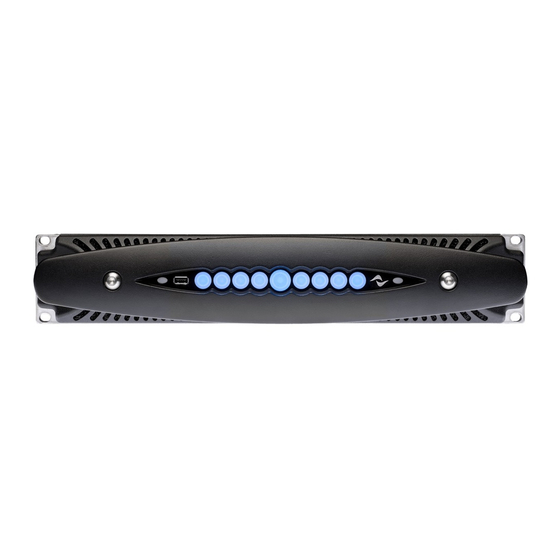
X8 Amplifier Platform
Service Manual
7-8
AES3 IN
5-6
ANALOG IN
8
7
6
5
3-4
AES3 IN
1-2
ANALOG IN
1=GND
2 = IN+
3 = IN-
4
3
2
1
POWER
OUTPUTS
CH 1/3/5/7
CH 2/4/6/8
Keep this manual
for future reference
Advertisement
Table of Contents

Related Manuals for powersoft X8


Summary of Contents for powersoft X8
- Page 1 X8 Amplifier Platform Service Manual MAINS POWER OUTPUTS “WARNING: To reduce The Risk of CH 1/3/5/7 Fire or Electric Shock, do not Expose AES3 IN AES3 IN this Apparatus to Rain or Moisture” CH 2/4/6/8 ANALOG IN ANALOG IN 1=GND...
- Page 2 Intentionally left blank...
- Page 3 The components to be replaced are clearly shown to help their Updating the Software identification. At the end of this guide you can find a detailed list with the description and the respective Powersoft internal Formatting a FAT32 USB Pen Drive reference code of the spare parts.
- Page 4 X8 | SERVICE MANUAL LED Configurations and Further References FW Version 1.7.6.30 RING LED LED STATUSES CENTRE LED SOLID LED is On BLINKING LED alternates from solid on to solid off PULSING LED dims from on to off in a fading fashion...
- Page 5 X8 | SERVICE MANUAL Armonía callback Main on/off switch WiFi MUTE ALL In order to indentify the unit into the Armonía Workspace, push on/off switch MUTE MUTE on the rightmost button. On the other hand, if you click on Un/ port Blink from the contextual menu of the amplifier into the Armonía...
- Page 6 X8 | SERVICE MANUAL Pulsing WHITE LED: WiFi Network ON or USB port in use Solid ON White LED: WiFi Network ON and USB port in use Solid ON White LED: Amp is connected to Armonía FAULT CONDITIONS LED CONFIGURATIONS Pulsing YELLOW Centre LED: Power supply temp.
- Page 7 X8 | SERVICE MANUAL Pulsing YELLOW Centre LED: CH Thermal Protection ON (70°) Pulsing YELLOW/RED Centre and Ring LEDs: CH Thermal Protection ON (85°) Pulsing RED Centre LED + Channel status Ring LED: Channel protection Enabled Possible Causes: • Out of range Rail Voltage •...
- Page 8 X8 | SERVICE MANUAL 1. Removing the Amplifier’s Cover By means of a Torx T20 Screwdriver, remove all 8 screws holding the side panels highlighted on (Fig. 1, 2). (Fig. 1) (Fig. 2) Remove the front panel by unscrewing the two highlighted Hex screws with a 6 mm Hex Screwdriver.
- Page 9 Colour Description Wi-Fi Module AMP Module Power Supply Module X Front Slot Ethernet Board DIGI/ADLINK Boards AC Wiring Diagrams Three-Phase Single-Phase Two-Phase L3 L2 L1 THE CONNECTOR AND ITS WIRING ARE COMPATIBLE THROUGHOUT THE WHOLE X SERIES PRODUCT LINE (X4-X8)
- Page 10 X8 | SERVICE MANUAL 2. Removing The Slot Ethernet Board By means of a Torx T10 Screwdriver, remove the two screws highlighted on (Fig. 6). Gently pull the Slot Ethernet Board outwards, removing it from its slot. Carefully extract the Slot Ethernet Board Removed Slot Ethernet Board with Dante Board Installed (Fig.
- Page 11 X8 | SERVICE MANUAL 3. Removing the Wi-Fi Module Locate the Wi-Fi module on the left side of the front panel. Gently pull the Wi-Fi Module outwards and remove it from its slot. (Fig. 7) Removed Wi.Fi Module (Fig. 7) 4.
- Page 12 X8 | SERVICE MANUAL Remove the earth grounding cable’s nut with a M7 socketed screwdriver. (Fig. 12) (Fig. 12) Detach the Mains Connector by unscrewing the two T10 Torx Screws. (Fig. 13) (Fig. 13) Unplug the FAN AMPS and FAN PWS cables highlighted on (Fig.
- Page 13 X8 | SERVICE MANUAL In order to remove the modules, unscrew the highlighted screws and gently pull the module towards the back side of the chassis. Carefully lift the modules in order to remove them from the chassis. Color Description...
- Page 14 X8 | SERVICE MANUAL 6. Removing the DIGI and ADLINK Boards • Extract all the audio modules. • Remove the Dante Board. • Remove the Wi-Fi Module Remove the front mesh panel by unscrewing the 4 T20 Torx screws highlighted on (Fig. 15) (Fig.
- Page 15 X8 | SERVICE MANUAL Flat Cable Replacement: Unscrew the marked screws by means of an M5 socketed screwdriv- Plug the CB000381.01 Flat Cables as portrayed er, remove the protection plate, and gently lift the Digi Board. Plug the CB000382.01 Flat Cables as portrayed Plug the CB000383.01 Flat Cables as portrayed...
- Page 16 X8 | SERVICE MANUAL SD Card Removal: Extraction of the SD Card can be done by removing the amplifier’s cover, locating the SD card on the side of the DIGI Board, and simply pressing on it, releasing the spring mechanism.
- Page 17 X8 | SERVICE MANUAL 8. Power Supply Verification Procedure Discharge the internal capacitor’s bank by connecting a 60W light bulb to the points indicated in the picture below. Connect a DC Power Supply via the CN000536 connector assembly. Limit the output current to 1.5A.
- Page 18 X8 | SERVICE MANUAL If the VRail Tensions are not present, check the fuses located underneath the capacitor’s bank, highlighted on (Fig. 20) (Fig. 20) Discharge the capacitor’s bank, reset the PSU Module into the chassis and repeat the test.
- Page 19 X8 | SERVICE MANUAL Connect the 2 PSU flat cables, and unplug all of the module’s flat cables. Connect the unit to a Variac, and slowly increase the voltage to 90Vac. Check the absorption. Check if the LEDs highlighted in the picture below are on.
- Page 20 X8 | SERVICE MANUAL Replacing the Fuses: Remove The Power Supply. Discharge the capacitor’s bank. Place the module on an flat surface and gently press on the fuses in order to release them from their slot. (Fig. 25) Lay the Module upside down so that the fuse end (Fig.
- Page 21 X8 | SERVICE MANUAL 9.Amp Modules Verification Checking the module’s diagnostic LEDs is quite tricky, since it is impossible (and extremely dangerous) to have the AMP Modules on whilst not properly inserted in the chassis. By angling your sight in the direction portrayed on (Fig.
- Page 22 X8 | SERVICE MANUAL Focusing the attention on U29 and U27, as portrayed on (Fig. 31), check the resistance between pins 4-7 and 1-7. (Fig. 32) Resistance 5K (approx.) (Fig. 31) 3K (approx.) In case of any short, replace the board.
- Page 23 (Fig. 36) 11. Updating the Software Formatting a FAT-32 USB Pen Drive: Plug a USB Pen Drive into a computer, follow the procedure portrayed in the following pictures. WARNING: This procedure must be followed for all Powersoft Products...
- Page 24 The package contains the software update file whose name is in the form: update-version#-model.bin Extract and place the downloaded file (ex update-v1.7.6.36-x8.bin) into a FAT32 Formatted USB Pen Drive. Press the central button in order to switch on the amplifier.
- Page 25 Area: Service Centre Rack AMPS - FW Accessories - X Series Info Settings Place the downloaded files (update-plain.sh, update-x8.sh) on a FAT32 Formatted USB Pen Drive. Place the downloaded files (update-plain.sh, update-x4.sh) in a FAT32 Formatted USB Pen Drive. (4,8,16 GB max) Open the file "update -plain.sh"...
- Page 26 The Event file will be named events.csv (Fig. 29) (Fig. 40) Attach this files to an e-mail and send it to service@powersoft.it Extracting the Log Files via SD Card With the amplifier turned off, remove the SD Card and place it in an sd card adaptor.
- Page 27 X8 | SERVICE MANUAL 13. Soft Reset - Resetting the IP Address This function is available from FW Versions 1.7.6.30 onward. It resets the IP to Dynamic Conditions. Default IP Address: 192.168.0.1 Turn the Amplifier on and keep the right and leftmost pushbuttons pressed until the “beep”.
- Page 28 X8 | SERVICE MANUAL Click on the Armonìa Logo Click on “Options” Click on “Communication Manager” Insert the following IP Address: 192.168.0.01 Click on Apply, and click on OK Click on to activate the network Click on to pause the network Click on “Discover”...
- Page 29 X8 | SERVICE MANUAL Once the Discovery Phase is complete (10 seconds) the square Double click on the Matrix Area. will turn Green. Double click on the Unit to continue the test. Select: ALL INPUTS ON CH1 Apply a 1KHz 1Vpp audio signal to CH1 Check for presence of the signal in all the other channel’s VMeters...
- Page 30 X8 | SERVICE MANUAL 16. Reworking Screws Under certain circumstances it may happen that one or more screws come loose. Remove all micromatches from the top of the amp (Fig. 44). (Fig. 44) Remove the screws highlighted on (Fig. 45) by means of a T20 Torx Screwdriver, extract them by means of a set of long needled pliers.
- Page 31 X8 | SERVICE MANUAL 17. Final Checklist Use the following list as a checklist once the amplifier has been successfully repaired. 1. The Device operates on all Mains configurations 2. The front LEDs operate correctly 3. Ethernet communication 4. Discovery 5.
- Page 32 X8 | SERVICE MANUAL 18. Restoring the Amplifier to its Factory Settings (Copying the PAM files from a Virtual Machine to a Real Machine) Import a Virtual AMP from the Model List. Open Discovery Remote Entities. Drag&Drop the real amp onto the virtual one.
- Page 33 X8 | SERVICE MANUAL 19. Troubleshooting diagrams Fault in the Power Supply Check the connection to the mains, wether Single, Dual, or Three phase. Contact the PASS Reassemble the PSU Powersoft Service Team Check the absorption of the PSU in DC (by itself)
- Page 34 X8 | SERVICE MANUAL Thermal limiter ON on Power Supply Update the unit’s Firware via Armonia Resolved or through the USB Pen Drive procedure Install the .pam default parameters and restart the unit Contact the Powersoft Service Team Check the PWS and AMP FAIL Fans’...
- Page 35 X8 | SERVICE MANUAL PWS Fan Failure Faulty connector - contact the Powersoft’s Service Team Unplug and plug the PWS Fan’s connector and switch the unit on Contact the Powersoft Service Team Check the PWS Fan’s FAIL viability FAIL Replace the PWS Fan Firmware Issue - versions prior to 1.7.6.30...
- Page 36 X8 | SERVICE MANUAL Firmware Issue - latest version Update the unit’s Firware via Armonia PASS Resolved or through the USB Pen Drive procedure Perform the SD Card Recovery procedure and turn the unit on Update the unit’s Replace thre DIGI+ADLINK...
- Page 37 X8 | SERVICE MANUAL Thermal Limiter ON on AMP Modules Unplug the Unit’s Input and Output connectors Replace the Flat Cables The issue persists on the same channel Update the Replace Place the unit’s Firware via suspected faulty AMP Armonia or through...
- Page 38 ME000896.01 Rear Panel CN000480 Mains Connector replacement (internal) Replacement Modules Kit Number Description SMD01037.R PSU Module KT000301.R X_SERIES_PLUG_ASSEMBLY KT000855.R KIT X8 Flat cable replacement SMD01005.R AMP Module SM001004.R DIGI Board SM001007.R ADLINK Board Old Fuses New Fuses FR000001.R FRONT SM000948.R...
- Page 39 Connect the device. Mains Status Monitor (1/2/3 Phases) Follow this procedure to activate the Wi-Fi connection and remotely access your Powersoft X Series amplifier platform. Access Ganging functions 1. Switch on the amplifier by holding down the central button on the front panel;...
- Page 40 X8 | SERVICE MANUAL By tapping the Wi-Fi button, it is possible to edit the ESSID, the Within the Input window, by tapping on the AES 3 button, it is default Password and the Band. possible to monitor the AES 3 Signal Status.
- Page 41 X8 | SERVICE MANUAL The intuitive layout of the routing matrix is very similar to the one Toggle between 3 EQ layers by sliding left to right or vice-versa. that is found in Armonía. Navigate to the Filter’s window by tapping the Filter Button Routing a signal is achieved by tapping on the desired routing option.
- Page 42 X8 | SERVICE MANUAL Fine tune the selected filter. OUTPUT CHANNEL Access the Output Channel window by tapping one of the Output Channel Buttons. SPEAKERS Access the Speaker preset manager window by tapping one of the The Output Channel window grants access to the Output’s Speaker button.
- Page 43 X8 | SERVICE MANUAL Within the Snapshot window it is possible to recall up to 50 user In order to clear the Gang Settings on a given row, tap the Clear defined Snapshots from the internal X Series Library, or from an button.
- Page 44 X8 | SERVICE MANUAL IMPORTANT SAFETY ADDENDUM The aim of this addendum is to describe the safety precautions to be undertaken when servicing any Powersoft amplifier/module. WE RECOMMEND THAT ALL SERVICE OPERATIONS ARE CARRIED OUT BY A TRAINED TECHNICIAN IF NOT EXPLICITLY STATED OTHERWISE, DISCONNECT THE AMPLIFIER FROM THE MAINS.
- Page 45 Tel: +39 055 735 0230 Fax: +39 055 735 6235 General inquiries: info@powersoft.it Sales: sales@powersoft.it Application & technical support: support@powersoft.it Service & maintenance: service@powersoft.it powersoft-audio.com Data are subject to change without notice. For latest update please refer to the online version available on www.powersoft-audio.com...
Need help?
Do you have a question about the X8 and is the answer not in the manual?
Questions and answers