Distech Controls ECLYPSE Installation Manual
Connected system controller
Hide thumbs
Also See for ECLYPSE:
- Installation manual (18 pages) ,
- Quick start manual (2 pages) ,
- Installation manual (17 pages)
Advertisement
Table of Contents
- 1 General Wiring Recommendations
- 2 Mounting Instructions
- 3 Input and Output Overview
- 4 Input Wiring
- 5 Output Wiring
- 6 Communications Wiring
- 7 Wireless Connection
- 8 Configuring the Controller
- 9 Using the Reset Button
- 10 Maintenance
- 11 North American Emissions Compliance
- 12 Complementary Information
- Download this manual
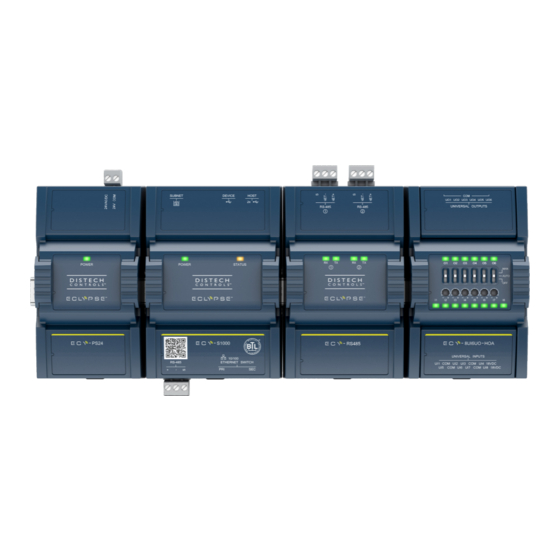
ECLYPSE™ Connected System Controller
Figure 1:
ECLYPSE Controller shown with the following Modules: ECY-PS24, ECY-S1000, ECY-RS485, and ECY-8UI6UO-HOA (front view)
Product Description
This document describes the hardware installation procedures for the ECLYPSE Connected System Controller. The ECLYPSE Connected System Con-
troller is a modular and scalable platform that is used to control a wide range of HVAC equipment, as well as lighting and power metering. It supports
BACnet/IP communication and is a listed BACnet Building Controller (B-BC). The ECLYPSE Connected System Controller consists of an automation and
connectivity server, power supply, and IO extension modules (see Table 2). This Connected System Controller provides advanced functionality such as
customizable control logic, Web-based design and visualization interface, logging, alarming, and scheduling.
General Installation Requirements
For proper installation and subsequent operation of each controller, pay special attention to the following recommendations:
£
Upon unpacking the product, inspect the contents of the carton for shipping damages. Do not install damaged modules.
£
Avoid areas where corroding, deteriorating or explosive vapors, fumes or gases may be present.
£
Ensure the mounting surface can support the controller, DIN rail, and any user-supplied enclosure.
£
Allow for proper clearance around the controller's enclosure, wiring terminals, and HOA switches to provide easy access for hardware configuration
and maintenance, and to ventilate heat generated by the controller.
£
The controller's mounting orientation must be horizontal with the controller's back attached to a vertical wall surface. Orient the controller with the
ventilation slots and power supply input terminal block connectors towards the top to permit proper heat dissipation. When installed in an enclosure,
select one that provides sufficient surface area to dissipate the heat generated by the controller and by any other devices installed in the enclosure.
A metal enclosure is preferred. If necessary, provide active cooling for the enclosure.
£
The controller's datasheet specifies the power consumption (amount of heat generated), the operating temperature range, and other environmental
conditions the controller is designed to operate under.
£
Ensure that all equipment is installed according to local, regional, and national regulations.
£
If the controller is used and/or installed in a manner not specified by Distech Controls, the functionality and the protection provided by the controller
may be impaired.
£
Equipment operated by an ECY-PS100-240 power supply must be wall-mounted or Din rail-mounted inside a supplementary enclosure rated as
IP20 or better that can only be accessed by trained personnel.
£
SELV (Separated Extra Low Voltage) inputs/outputs must be connected to other SELV equipment inputs/outputs.
Any type of modification to any Distech Controls product will void the product's warranty.
Take reasonable precautions to prevent electrostatic discharges to the controller when installing, servicing or
operating the controller. Discharge accumulated static electricity by touching one's hand to a well-grounded
object before working with the controller.
I n s t a l l a t i o n G u i d e
Advertisement
Table of Contents

Related Manuals for Distech Controls ECLYPSE


Summary of Contents for Distech Controls ECLYPSE
- Page 1 Ensure that all equipment is installed according to local, regional, and national regulations. £ If the controller is used and/or installed in a manner not specified by Distech Controls, the functionality and the protection provided by the controller may be impaired.
-
Page 2: General Wiring Recommendations
Device Markings (Symbols) Certain markings (symbols) can be found on the controller and are defined as follows: Symbol Description CE marking: the device conforms to the requirements of applicable EC directives. Double Insulation marking: These controllers are built using double insulation. Products must be disposed of at the end of their useful life according to local regulations. - Page 3 Module Enclosure Dimensions 3.57" 90.67 0.4" 1.09 2.31" 58.56 Inter-Connection Gap: 0.01" 0.40 0.83 21.08 4.74" 120.31 3.18" 80.82 5.13" 130.29 0.73 18.54 0.39" 9.98 0.06" 1.44 Front Back 3.33" 84.47 Inches Millimeters Figure 3: ECY-S1000 Module 0.40" 10.25 2.85" 72.38 2.31"...
- Page 4 4.08" 103.65 0.44" 11.13 Inter-Connection Gap: 0.01" 0.40 2.31" 58.56 0.83 21.13 4.74" 120.31 3.18" 80.82 5.24 133.03 0.72 18.39 Back Front 0.06" 1.44 3.83" 97.33 Inches Millimeters Figure 5: 100 to 240 VAC Power Supply IO Modules come in the following widths. Models Width Narrow...
- Page 5 5.15" 130.07 2.31" 58.56 Inter-Connection Gap: 0.01" 0.40 0.83 21.08 AUTO 4.74" 120.31 3.18" 80.82 4.80" 121.75 0.73 18.54 Front Back 0.06" 1.44 4.94" 125.32 Inches Millimeters Figure 7: IO Module: Wide Width 3.20 [81.17] Inter-Connection Gap: 0.01 [0.40] 2.31" 58.56 0.51 [12.90] 0.83 [21.08] 4.74 [120.31]...
- Page 6 Inches [Millimeters] Figure 9: ECY-MBUS Communication Module See the ECLYPSE Selection Tool to determine the width of a specific assembly and the assembly order. Status LED, DIP Switch, and Jumper Identification and Configuration ECY-S1000 The Control, Automation and Connectivity Server has the following onsite configurable jumpers or DIP switches located inside the cover. Orient the cir- cuit board as shown in the figure below.
- Page 7 ECY-8UI, ECY-6UO, ECY-6UO-HOA, ECY-4UI4UO, ECY-4UI4UO-HOA, ECY-8UI6UO, ECY-8UI6UO-HOA, ECY-8UI6DOT, and ECY-8UI6DOT-HOA These IO modules have the following onsite configurable DIP switches located inside the cover. Orient the circuit board as shown in the figure below. UI Input Option Configuration 0-20mA UI3 UI4 UI5 UI6 UI7 UI8 UI Input Option Configuration UO Output Option...
-
Page 8: Mounting Instructions
RS-485 EOL Termination Configuration Settings for DIP Switches S1 & S2 RS-485 EOL Termination OFF* BIAS+ BIAS- S1 Operates on Port #1 S2 Operates on Port #2 * Factory-default positions Internal View Figure 12: ECY-RS485 DIP Switch Locations Mounting Instructions Each module can be mounted on a DIN rail for fast installation and easier maintenance. Each module also has two pre-molded mounting holes allowing the module to be mounted in a panel or on a wall. - Page 9 The ECY-PS Module Supplies Power to Modules Connected to the Right; up to the next ECY-PS Module The ECY-S1000 Module Controls all Modules Connected to the Right When a Communications Module is used, install it immediately to the right of the ECY-S1000 before any input/output module. ECY-PS ECY-S1000 ECY-RS485...
- Page 10 Figure 17: Latches to Unlock a Module’s Front Assembly (ECY-S1000, left; ECY IO Module, right) ð For ECY IO modules: Separate the front and back base by opening and pulling the hinged gull-wing covers, thereby separating the electrical connectors between the two halves. Figure 18: ECY IO Modules have Gull-wing Front Assembly 2.
- Page 11 Each ECY-PS24 power supply can supply a maximum of 30W to loads connected to the right of it, up to the next connected power supply. See the ECLYPSE Selection Tool to calculate the number of Input/Output Extension Modules that can operate with each power supply, the number of power sup- plies required, and their location.
- Page 12 Each ECY-PS100-240 power supply can supply a maximum of 40W to loads connected to the right of it, up to the next connected power supply. See the ECLYPSE Selection Tool to calculate the number of Input/Output Extension Modules that can operate with each power supply, the number of power sup- plies required, and their location.
-
Page 13: Input And Output Overview
Input and Output Overview Each ECY IO module has a number of physical connections for inputs and/or outputs. These inputs and outputs are labelled on the ECY IO modules ac- cording to the tables below. Input and output options must be configured properly in EC-gfxProgram to ensure correct input readings and output values. The controller's license may have separate limits that reduce the availability of certain options. -
Page 14: Output Wiring
Sensor Input Type ECY IO Input Connection Diagram modules’ Input Des- ignation £ Pulse input used with a 2-wire sensor powered by its own power source – this in- £ +5 VDC Controller put supports a maximum input frequency of 1Hz (500ms minimum ON/OFF). Pulse Input Connect the pulse input according to the figure for a pulse meter that can pull- Equivalent... - Page 15 Control Output Type ECY IO mod- Output Connection Diagram ules’ Output Designation £ £ Discrete 0 or 12VDC digital, Pulse, or PWM output controlling a From 12VDC relay. Maximum 60 mA (minimum load resistance 200Ω). Digital Output 12VDC Relay £ 0 to 20mA current output –...
-
Page 16: Communications Wiring
IP addressing, radio path planning (when the ECLYPSE Wi-Fi Adapter is connected to the con- troller), etc. It can be downloaded from our website. For optimal performance, use Distech Controls category 5e network cable or refer to the ECLYPSE User Guide for cable specifications. - Page 17 PC’s network cable from its Ethernet port. The controller’s factory-default hostname is eclypse-xxxxxx.local where xxxxxx is the last 6 characters of the MAC address printed on a sticker located on the side of the controller. See above.
- Page 18 Connecting to the Controller’s Configuration Web Interface At the first connection to an ECLYPSE Controller you will be forced to change the password to a strong password for the admin account to protect ac- cess to the controller. In Network Settings, configure the controller’s network parameters so that they are compatible with your network. See the ECLYPSE User Guide for more information about network settings and how to secure the controller.
- Page 19 It can be downloaded from our website. For optimal per- formance, use Distech Controls 24 AWG (0.65 mm) stranded, twisted pair shielded cable or refer to the ECLYPSE User Guide for cable specification.
- Page 20 Communications Wiring [pg. 16]). For more connection options, refer to the ECLYPSE User Guide. The RS-485 port must be configured in EC- gfx Program prior to use. Modbus devices are integrated into EC- gfx Program using the EC- gfx Program Mod- bus device block.
-
Page 21: Using The Reset Button
Directive applies to standalone products, for example, products that can function entirely on their own and are not a part of another system or piece of equipment. For this reason Distech Controls products are exempt from the WEEE Directive. Nevertheless, Distech Controls products are marked with the WEEE symbol , indicating devices are not to be thrown away in municipal waste. -
Page 22: North American Emissions Compliance
Specifications subject to change without notice. Distech Controls, the Distech Controls logo, Innovative Solutions for Greener Buildings, EC-Net, ECO-Vue, Allure, and Open-To-Wireless are trademarks of Distech Controls Inc.; LonWorks, LON, and LNS are registered trademarks of Echelon Corporation; BACnet is a registered trademark of ASHRAE; BTL is a registered trademark of the BACnet Manufacturers Association; Niagara Framework is a registered trademark of Tridium, Inc.;...
Need help?
Do you have a question about the ECLYPSE and is the answer not in the manual?
Questions and answers