Advertisement
ECL-VAV Series & ECL-103 Controllers
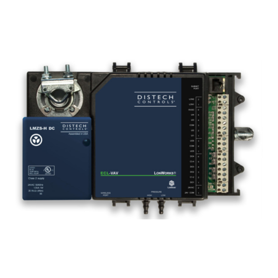
Figure 1:
From left to right: ECL-VAV and ECL-103
Product Description
This document describes the hardware installation procedures for the
Single Duct Variable Air Volume / Variable Volume Temperature
Controllers (ECL-VAVS-O, ECL-VAVS, ECL-VAV, ECL-VVTS, and
ECL-VAV-N), and the 10-Point Programmable Controller (ECL-103).
The Distech Controls Variable Air Volume / Variable Volume
Temperature product line is designed to control and monitor various
types of HVAC equipment such as baseboards, single and multi-stage
duct heaters, fans, valves, lights, etc. When connected to a Wireless
Receiver, this product line can be used with a variety of wireless
battery-less sensors and switches.
The ECL-VAV model supports a range of Smart Room Control
modules that expand the controller's range of control to include lighting
and shades/sunblinds with the ECx-Light and ECx-Blind series control
modules. This controller also supports the EC-Multi-Sensor ceiling-
mounted sensor and its associated EC-Remote remote control.
Each controller uses the L
ON
communication between controllers and are L
This document describes the hardware installation procedures for the
following controllers: ECL-VAVS-O, ECL-VAVS, ECL-VAV, ECL-VVTS,
ECL-VAV-N and ECL-103.
For more information on the specific layout and functionality
of each controller, please refer to their individual
datasheets.
General Installation Requirements
For proper installation and subsequent operation of the controller, pay
special attention to the following recommendations:
-
It is recommended that the controller(s) be kept at room
temperature for at least 24 hours before installation to allow any
condensation that may have accumulated due to low temperature
during shipping/storage to evaporate.
®
W
technology for peer-to-peer
ORKS
M
certified.
ON
ARK
H a r d w a r e I n s t a l l a t i o n G u i d e
-
Upon unpacking the product, inspect the contents of the carton for
shipping damages. Do not install damaged controllers.
-
Avoid areas where corroding, deteriorating or explosive vapors,
fumes or gases may be present.
-
Allow for proper clearance around the controller's enclosure, wiring
terminals, and service pin (see Figure 14) to provide easy access
for hardware configuration and maintenance, and to ventilate heat
generated by the controller. Remember to record the 12-character
®
Neuron
ID located on a sticker on top of the device (shown on a
sticker below the barcode), for later commissioning. When installed
in an enclosure, select one that provides sufficient surface area to
dissipate the heat generated by the controller and by any other
devices installed in the enclosure. A metal enclosure is preferred. If
necessary, provide active cooling for the enclosure.
-
The controller's datasheet specifies the power consumption
(amount of heat generated), the operating temperature range, and
other environmental conditions the controller is designed to operate
under.
-
Ensure that all equipment is installed according to local, regional,
and national regulations.
-
Do not drop the controller or subject it to physical shock.
-
If the controller is used and/or installed in a manner not specified by
Distech Controls, the functionality and the protection provided by
the controller may be impaired.
Any type of modification to any Distech Controls product will
void the product's warranty.
Before installation of the Wireless Receiver, verify that local
communication regulations allow the installation of wireless
devices and available frequencies to be supported in your
area. Refer to the Open-to-Wireless™ Solution Guide for
more information.
Take reasonable precautions to prevent electrostatic
discharges to the controller when installing, servicing or
operating the controller. Discharge accumulated static
electricity by touching one's hand to a well-grounded object
before working with the controller.
Advertisement
Table of Contents

Subscribe to Our Youtube Channel
Related Manuals for Distech Controls ECL-VAV Series


Summary of Contents for Distech Controls ECL-VAV Series
- Page 1 ECL-VAV-N and ECL-103. For more information on the specific layout and functionality Any type of modification to any Distech Controls product will of each controller, please refer to their individual void the product’s warranty. datasheets.
-
Page 2: General Wiring Recommendations
Controller Dimensions & Components Device Markings (Symbols) Certain markings (symbols) can be found on the controller and are defined as: Symbol Description CE marking: the device conforms to the requirements of applicable EC directives. Products must be disposed of at the end of their useful life according to local regulations. -
Page 3: Mounting Instructions
5. Press and hold down the Actuator Clutch for Manual Adjustment button (see Figure 4), and turn the controller’s shaft coupler until it touches the mechanical end-stop to either the fully closed position (90° boxes) or the fully open position (45° and 60° boxes). 6. - Page 4 45M (150 feet) 3 * Factory-default positions 30M (100 feet) 5 Figure 9: ECL-VAV Series and ECL-103 Controller Jumper Locations 1. Typical VAV with 1 Allure Series Communicating Sensor (without CO2 sensor) and actuator activated. No external loads. 2. Typical VAV with 1 Allure Series Communicating Sensor (without CO2 sensor), 2 triac loads (1.6 VA each), 1 analog output (20 mA),...
-
Page 5: Input Wiring
Input Wiring Table 2 shows the available universal input (UIx) wiring methods. Before connecting a sensor to the controller, refer to the installation guide of the equipment manufacturer. For a wire length less than 75’ (23m), either a shielded or unshielded 18AWG wire may be used. For a wire up to 200’... -
Page 6: Output Wiring
Output Wiring Table 3 shows the available output wiring methods. Before connecting an output device (actuator, relay, etc.) to the controller, refer to the datasheet and installation guide of the equipment manufacturer. For a wire length less than 75’ (23m) long, either a shielded or unshielded 18AWG wire may be used. For a wire length up to 200’... -
Page 7: Communications Wiring
It is important to use proper network terminators depending on the type of network topology used. Failure to do so might result in communication errors between controllers. Figure 12: Location of the Wireless Receiver’s telephone socket Selecting Network Terminators Topology Distech Controls Part # PDIDI-BT-TP10XX Free PDIDI-FT-TP10XX 7/12... -
Page 8: Terminal Block Cover
For this reason Distech Controls products are exempt from the WEEE Directive. Nevertheless, Distech Controls products are marked with the... - Page 9 Typical Variable Air Volume Application Wiring Diagram Back of Allure EC-Smart-Vue EOL Enabled at the last sensor at the end of the Bus From Previous Device Network ® ORKS To Next Device Wireless Port (beneath cover) Heating Floating Actuator Allure PRESSURE HIGH 24VAC...
-
Page 10: Troubleshooting Guide
Troubleshooting Guide Controller is powered but does not turn on Fuse has blown Disconnect the power. Check the fuse integrity. Reconnect the power. Power supply polarity Verify that consistent polarity is maintained between all controllers and the transformer. Ensure that the 24VCOM terminal of each controller is connected to the same terminal on the secondary side of the transformer. - Page 11 Status LED– Normal Operation One fast blink Initialization: The device is starting up. Fast blink continuous: Firmware upgrade in progress. Controller operation is temporarily unavailable. The new firmware is being loaded into memory. This takes a few seconds. Do not interrupt power to the device during this time. (150ms On, 150ms Off, continuous) The Status LED is always OFF The controller is operating normally.
- Page 12 ©, Distech Controls Inc., 2014 to 2015. All rights reserved. Images are simulated. While all efforts have been made to verify the accuracy of information in this manual, Distech Controls is not responsible for damages or claims arising from the use of this manual. Persons using this manual are assumed to be trained HVAC specialist / installers and are responsible for using the correct wiring procedures and maintaining safe working conditions with fail-safe environments.
Need help?
Do you have a question about the ECL-VAV Series and is the answer not in the manual?
Questions and answers