Table of Contents
Advertisement
Quick Links
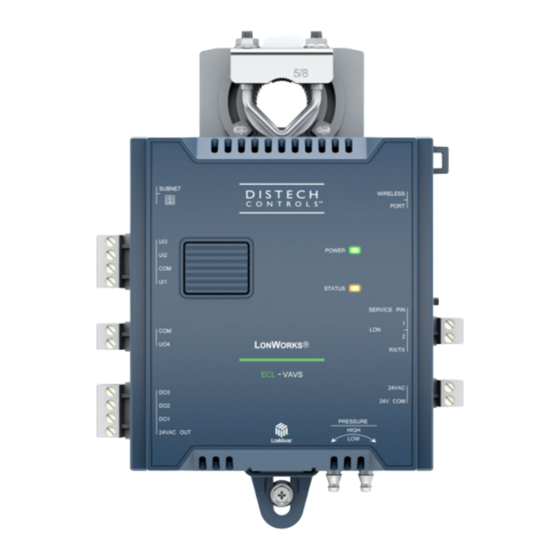
ECL-VAVS Controller
Figure 1:
ECL-VAVS Controller
Product Description
This document describes the hardware installation procedures for the ECL-VAVS Single Duct Variable Air Volume Controllers.
The Distech Controls Variable Air Volume product line is designed to control and monitor various types of HVAC equipment such as baseboards, single
and multi-stage duct heaters, fans, valves, lights, etc. When connected to a Wireless Receiver, this product line can be used with a variety of wireless
battery-less sensors and switches.
Each controller uses the L
W
ON
ORKS
General Installation Requirements
For proper installation and subsequent operation of the device, pay special attention to the following recommendations:
£
It is recommended that the controller(s) be kept at room temperature for at least 24 hours before installation to allow any condensation that may
have accumulated due to low temperature during shipping/storage to evaporate.
£
Upon unpacking, inspect the contents of the carton for shipping damages. Do not install a damaged device.
£
The device is designed to operate under environmental conditions that are specified in its datasheet.
£
Ensure proper ventilation of the device and avoid areas where corroding, deteriorating or explosive vapors, fumes or gases may be present.
£
Record the 12-character Neuron
£
Allow for proper clearance around the device's enclosure and wiring terminals to provide easy access for hardware configuration and maintenance.
£
When installing in an enclosure, select one that provides sufficient surface area to dissipate any heat generated by the device and by any other de-
vices installed in the enclosure. A metal enclosure is preferred. If necessary, provide active cooling for the enclosure.
£
The device's datasheet specifies the power consumption (amount of heat generated), the operating temperature range, and other environmental
conditions the device is designed to operate under.
£
Ensure that all equipment is installed according to local, regional, and national regulations.
£
Do not drop the device or subject it to physical shock.
£
If the device is used and/or installed in a manner not specified by Distech Controls, the functionality and the protection provided by the device may
be impaired.
Any type of modification to any Distech Controls product will void the product's warranty
Before installation of the Wireless Receiver, verify that local communication regulations allow the installation of wireless devices and
available frequencies to be supported in your area. Refer to the Open-to-Wireless™ Application Guide for more information.
Take reasonable precautions to prevent electrostatic discharge to the device when installing, servicing or during operation. Discharge
accumulated static electricity by touching one's hand to a well-grounded object before working with the device.
®
technology for peer-to-peer communication between controllers and are L
®
ID located on either end of the device (shown on a sticker below the barcode), for later commissioning.
I n s t a l l a t i o n G u i d e
M
certified.
ON
ARK
Advertisement
Table of Contents

Related Manuals for Distech Controls ECL-VAVS


Summary of Contents for Distech Controls ECL-VAVS
- Page 1 Do not drop the device or subject it to physical shock. £ If the device is used and/or installed in a manner not specified by Distech Controls, the functionality and the protection provided by the device may be impaired. Any type of modification to any Distech Controls product will void the product’s warranty Before installation of the Wireless Receiver, verify that local communication regulations allow the installation of wireless devices and available frequencies to be supported in your area.
-
Page 2: General Wiring Recommendations
Device Markings (Symbols) Certain markings (symbols) can be found on the controller and are defined as follows: Symbol Description CE marking: the device conforms to the requirements of applicable EC directives. UKCA marking: the device conforms to the requirements of applicable Great Britain regulations. Products must be disposed of at the end of their useful life according to local regulations. -
Page 3: Mounting Instructions
Sliding Grommet Inches [Millimeters] Figure 4: ECL-VAVS Controller with Terminal Covers Dimensions Mounting Instructions Each controller is specially designed for easy installation either directly on an air duct or in a panel by using the integrated mounting collar and the screw that is provided with the controller. - Page 4 90° 0° 180° VAV Box Shaft 270° Figure 5: Recommended Mounting Position Angle Range Mounting Procedure for Terminal Covers Terminal covers can be added to any VAV controller to protect inadvertent contact with the controller’s electrical connections. £ A terminal cover kit can be added to both sides of the controller. Controllers with terminal block covers can only be mounted on a flat surface that is sufficiently large to provide space around the installation.
- Page 5 3. Screw the controller onto the VAV box through the controller’s Sliding Grommet. The sliding grommet allows the controller to move back and forth when the VAV box’s damper shaft is off center. Ensure to center the grommet along its travel range and ensure that the screw enters the VAV box at a right angle.
-
Page 6: Power Wiring
It can ORKS be downloaded from the Distech Controls’ Documentation and Resources Portal. It is recommended to wire only one controller per 24VAC transformer. When calculating a controller’s power consumption to size the 24VAC transformer, you must also add the external loads the controller is going to supply, including the power consumption of any connected subnet module (for example, Allure™... -
Page 7: Daisy-Chain Wiring
Daisy Chain Performance VAVS + SmartVue (AWG18) VAVS + SmartVue (AWG16) VAVS + SmartVue + 2DO (1,6VA each) (AWG18) VAVS + SmartVue + 2DO (1,6VA each) (AWG16) VAVS + SmartVue + SmartVue CO2 + 2DO (1,6VA each) (AWG18) VAVS + SmartVue + SmartVue CO2 + 2DO (1,6VA each) (AWG16) (30) (45) (60) -
Page 8: Input Wiring
Controller 1 Fuse: 4 A Max. Fast Acting 24V AC 24V COM 24 VAC Transformer OPTIONAL GROUNDING: All grounding is optional for LON networks Controller 24V AC 24V COM Figure 12: Power Wiring Input Wiring Before connecting a sensor to the controller, refer to the installation guide of the equipment manufacturer. £... -
Page 9: Output Wiring
Sensor Input Type Input Connection Diagram £ 0 to 20mA input used with a sensor powered by its own power source. 165Ω 249Ω ¼W To Analog- 0-20mA To-Digital Sensor Converter £ Voltage input used with a 3-wire 0 to 10VDC sensor powered by an external 24 AC/DC power supply. -
Page 10: Communications Wiring
Guide for extensive information and requirements for the connection of the Allure Series. It contains information about network topology and length, cable type, setting the Subnet ID, etc. It can be downloaded from the Distech Controls’ Documentation and Resources Portal. See also the Hardware In- stallation Guide supplied with the Allure Series. -
Page 11: Wireless Installation
If inserting multiple wires in the terminals, ensure to properly twist wires together prior to inserting them into the terminal connectors. For more information and detailed explanations on network topology and wire length restrictions, refer to the Network Guide, which can be downloaded from the Distech Controls’ Documentation and Resources Portal. Wireless Installation When connected to a Wireless Receiver, controllers can receive input signals from a wide selection of wireless devices. -
Page 12: Maintenance
Directive applies to standalone products, for example, products that can function entirely on their own and are not a part of another system or piece of equipment. For this reason Distech Controls products are exempt from the WEEE Directive. Nevertheless, Distech Controls products are marked with the WEEE symbol , indicating devices are not to be thrown away in municipal waste. -
Page 13: Troubleshooting Guide
Troubleshooting Guide Controller is powered but does not turn on Fuse has blown Disconnect the power. Check the fuse integrity. Reconnect the power. Power supply polarity Verify that consistent polarity is maintained between all controllers and the transformer. Ensure that the 24VCOM terminal of each controller is connected to the same terminal on the secondary side of the transformer. - Page 14 ©, Distech Controls Inc., 2012 - 2022. All rights reserved. Images are simulated. While all efforts have been made to verify the accuracy of information in this manual, Distech Controls is not responsible for damages or claims arising from the use of this manual.
Need help?
Do you have a question about the ECL-VAVS and is the answer not in the manual?
Questions and answers