Table of Contents
Advertisement
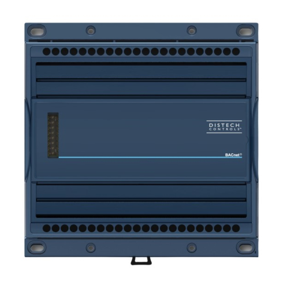
ECB-PTU Series
Product Description
This document describes the hardware installation procedures for the ECB-PTU Series BACnet controllers.
The Distech Controls ECB-PTU Series controllers are designed to control and monitor powered terminal units such as powered fan coil units, heat
pumps, chilled ceilings and small air handling units.
This product line includes the following controllers: ECB-PTU-107, ECB-PTU-207, ECB-PTU-208, ECB-PTU-307, and ECB-PTU-308.
The ECB-PTU Series are compatible with the ECx-Light/Blind lighting and sunblind expansion modules (refer to the ECx-Light/Blind Series Expansion
Modules Hardware Installation Guide).
Each controller uses the BACnet® MS/TP LAN communication protocol.
This document describes the hardware installation procedures for the following controllers: ECB-PTU-107, ECB-PTU-207, ECB-PTU-208, ECB-PTU-307
and ECB-PTU-308.
These controllers are all built on a similar platform but have different numbers of inputs and outputs. Moreover, each
individual model has different amounts of digital and/or analog outputs. For more information on the specific layout
and functionality of each controller, please refer to their individual datasheets and user guides.
General Installation Requirements
For proper installation and subsequent operation of the device, pay special attention to the following recommendations:
£
It is recommended that the controller(s) be kept at room temperature for at least 24 hours before installation to allow any condensation that may
have accumulated due to low temperature during shipping/storage to evaporate.
£
Upon unpacking, inspect the contents of the carton for shipping damages. Do not install a damaged device.
£
The controller should be installed in an appropriate ventilated enclosure with minimum dimensions 240 x 240 x 100 mm.
£
Avoid areas where corroding, deteriorating, or explosive vapors, fumes or gases may be present.
£
Allow for proper clearance around the controller's enclosure, wiring terminals, and service pin, in order to provide easy access for hardware configu-
ration, and in order to ventilate the heat generated by the controller.
£
Orient the controller with the ventilation slots towards the top to permit proper heat dissipation. When installed in an enclosure, select one that pro-
vides sufficient surface area to dissipate the heat generated by the controller and by any other devices installed in the enclosure. A metal enclosure
is preferred. If necessary, provide active cooling for the enclosure.
£
The device's datasheet specifies the power consumption (amount of heat generated), the operating temperature range, and other environmental
conditions the device is designed to operate under.
£
Ensure that all equipment is installed according to local, regional, and national regulations.
I n s t a l l a t i o n G u i d e
Advertisement
Table of Contents

Related Manuals for Distech Controls ECB-PTU Series


Summary of Contents for Distech Controls ECB-PTU Series
- Page 1 This document describes the hardware installation procedures for the ECB-PTU Series BACnet controllers. The Distech Controls ECB-PTU Series controllers are designed to control and monitor powered terminal units such as powered fan coil units, heat pumps, chilled ceilings and small air handling units.
-
Page 2: Device Markings
Do not drop the device or subject it to physical shock. £ If the device is used and/or installed in a manner not specified by Distech Controls, the functionality and the protection provided by the device may be impaired. £... -
Page 3: General Wiring Recommendations
General Wiring Recommendations Turn off power before any kind of servicing. £ All wiring must comply with electrical wiring diagrams as well as national and local electrical codes. £ To connect the wiring to a device, use the terminal connectors. Use a small flat screwdriver to tighten the terminal connector screws once the wires have been inserted (strip length: 0.25’’... -
Page 4: Device Dimensions
Wall-Mounted Installation 1. Use the mounting holes to mark the location of any holes that need to be drilled. 2. Drill the holes. 3. Clean the surface and mount the controller using the appropriate screw types. Figure 3: Wall-mounted controller Device Dimensions 132 (5.2) 44 (1.7) 132 (5.2) -
Page 5: Power Wiring
Power Wiring Voltage: 100-240 VAC; -15%/+10%; 50/60 Hz Overvoltage Category II - 2.5 kV Model Typical Consumption Max. Consumption ECB-PTU-107 < 0.9 W + all external loads 4.0 A ECB-PTU-207 < 0.9 W + all external loads 4.0 A ECB-PTU-208 <... - Page 6 Wiring Digital Inputs (Six – Dix – Six) This input configuration is used to monitor digital dry contacts. Figure 6: Digital input - Dry contact (NO & NC) Wiring Voltage Inputs (UIx) Voltage inputs have a range of 0 to 10 Vdc. Connect the voltage input according to the following figure. The transducer used must be powered externally. Figure 7: Voltage input –...
-
Page 7: Output Wiring
Output Wiring Depending on models, these controllers have physical connections for analog outputs, digital powered relay outputs, digital relay contact outputs, and digital triac outputs. These outputs are all software-configurable. All output wiring, except for electric heater outputs, must be connected using the provided detachable connectors. Electric heater output wiring is made directly through the onboard connector. - Page 8 Figure 13: Relay Contact outputs - Electric Heater (I-Electric Heater > I-Max ) Wiring Triac Outputs Depending on models, triac outputs provide either the same voltage as the power supply (100-240 VAC) or 24 VAC. Refer to the controller’s Datasheet for further specifications. The triac outputs can also be used to turn equipment and devices on and off (two-state outputs) and to control valve and damper actuators using Pulse Width Modulation (PWM).
- Page 9 Figure 18: 0-10 V controller-powered valve wiring (ECB-PTU-107/207/307) Figure 19: 0-10 V controller-powered valve wiring (ECB-PTU-208/308) Wiring Analog Outputs (AOx) Analog outputs can be configured to provide either a discrete signal of 0 or 12 VDC or a linear signal ranging from 0 to 10 VDC. The discrete signal can be used to generate a pulse wave modulation (PWM) signal or a simple two-state signal.
-
Page 10: Communications Wiring
The Network Guide provides extensive information and requirements to implement a BACnet MS/TP network. It contains information about network and sub network length, cable type, device addressing, etc. It can be downloaded from our website. For optimal performance, use Distech Controls 0.5 mm²... - Page 11 ECB-PTU Series controllers can be commissioned with an Allure EC-Smart-Vue sensor by connecting it to the controller. The default Subnet ID for an Allure EC-Smart-Vue sensor is 1. To commission an ECB-PTU Series controller, the Allure EC-Smart-Vue sensor’s Subnet ID must be set to 1. If the...
- Page 12 Commissioning ECB-PTU Series Controllers When using an Allure EC-Smart-Vue sensor for commissioning ECB-PTU Series controllers (the DIP switch located on the faceplate is set to 0 (all off) and before code is downloaded to the controller from EC-gfxProgram), connect an Allure EC-Smart-Vue sensor to the controller with its Subnet ID set to 1.
- Page 13 Setting the BAUD Rate (optional) By default, the BAUD rate for the controller is set to automatically detect the current communication BAUD rate of the connected BACnet MS/TP network (AUTO). This is the preferred setting for a controller. However, at least one controller on the BACnet MS/TP network data bus must have its BAUD rate set.
-
Page 14: Wireless Installation
Wireless Installation When connected to a Wireless Receiver, controllers can receive input signals from a wide selection of wireless devices. Compatible wireless devices in- clude temperature sensors, duct sensors, window/door contacts and light switches. These devices are easy to install, and can be mounted on a wide range of building materials. - Page 15 Tie wraps can then be used to group wires together and attach them securely to the strain relief in an effort to relieve undue tension. Distech Controls recommends using 0.184’’ (4.6 mm) wide tie wraps with a 50 lbs (220 N) tensile strength to attach wires to the strain relief.
- Page 16 Figure 28: Installing the terminal block cover 16 / 24...
-
Page 17: Fcc Statement
Directive applies to standalone products, for example, products that can function entirely on their own and are not a part of another system or piece of equipment. For this reason Distech Controls products are exempt from the WEEE Directive. Nevertheless, Distech Controls products are marked with the WEEE symbol , indicating devices are not to be thrown away in municipal waste. - Page 18 Typical ECB-PTU-107 Wiring Diagram CONNECTORS CONNECTORS NET+ NET+ NET- NET- SI3 = SpaceTemp / ReturnTemp / DischargeTemp / WaterTemp / Unused SHIELD SHIELD UI2 = SpOffset / ReturnTemp / DischargeTemp / WaterTemp / Unused COMMON COMMON TEMP TEMP SETPOINT SETPOINT FANSPEED FANSPEED EC-Sensor-SOF...
- Page 19 Typical ECB-PTU-207 Wiring Diagram EC-Sensor-SO CONNECTORS 24 Vac CO2 Sensor CO2 Sensor 24 AC SI3 = SpaceTemp / ReturnTemp / DischargeTemp / WaterTemp / Unused NET+ NET- UI2 = SpOffset / ReturnTemp / DischargeTemp / WaterTemp / Unused OU T SHIELD COMMON TEMP...
- Page 20 Typical ECB-PTU-208 Wiring Diagram EC-Sensor-SO CONNECTORS CO2 Sensor CO2 Sensor 24 AC SI3 = SpaceTemp / ReturnTemp / DischargeTemp / WaterTemp / Unused NET+ NET- UI2 = SpOffset / ReturnTemp / DischargeTemp / WaterTemp / Unused SHIELD COMMON TEMP SETPOINT Subnet MAC Pass-Through Pass-Through...
- Page 21 Typical ECB-PTU-307 Wiring Diagram EC-Sensor-SO CONNECTORS CO2 Sensor CO2 Sensor 24 AC SI3 = SpaceTemp / ReturnTemp / DischargeTemp / WaterTemp / Unused NET+ NET- UI2 = SpOffset / ReturnTemp / DischargeTemp / WaterTemp / Unused SHIELD COMMON TEMP SETPOINT Subnet MAC Pass-Through Pass-Through...
- Page 22 Typical ECB-PTU-308 Wiring Diagram EC-Sensor-SO CONNECTORS CO2 Sensor CO2 Sensor 24 AC SI3 = SpaceTemp / ReturnTemp / DischargeTemp / WaterTemp / Unused NET+ NET- UI2 = SpOffset / ReturnTemp / DischargeTemp / WaterTemp / Unused SHIELD COMMON TEMP SETPOINT Subnet MAC Pass-Through Pass-Through...
-
Page 23: Troubleshooting Guide
Troubleshooting Guide Controller is powered but does not turn on Fuse has blown Disconnect the power from the controller. Check the fuse integrity. Reconnect power to the controller. Controller cannot communicate on a BACnet MS/TP network Network not wired properly Double check that the wire connections are correct. - Page 24 ©, Distech Controls Inc., 2013 - 2022. All rights reserved. Images are simulated. While all efforts have been made to verify the accuracy of information in this manual, Distech Controls is not responsible for damages or claims arising from the use of this manual.
Need help?
Do you have a question about the ECB-PTU Series and is the answer not in the manual?
Questions and answers