Table of Contents
Advertisement
Quick Links
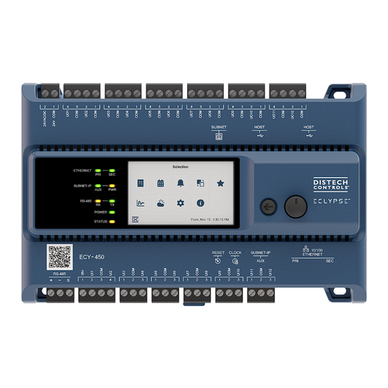
ECY-400 Series
Product Description
The ECY-400 Series controllers are designed to control various building automation applications such as air handling units, multi-zone applications,
chillers, boilers, pumps, cooling towers, and roof top units. They support BACnet/IP communications and are listed BACnet Building Controllers (B-BC).
These programmable controllers come with an embedded web server that enables web-based application configuration and a visualization interface.
They also feature embedded scheduling, alarming, and logging. Control logic and graphic user interface can be customized as required for the applica-
tion.
General Installation Requirements
For proper installation and subsequent operation of each controller, pay special attention to the following recommendations:
£
Upon unpacking the product, inspect the contents of the carton for shipping damages. Do not install damaged modules.
£
Avoid areas where corroding, deteriorating or explosive vapors, fumes or gases may be present.
£
Ensure the mounting surface can support the controller, DIN rail, and any user-supplied enclosure.
£
Allow for proper clearance around the controller's enclosure and wiring terminals to provide easy access for hardware configuration and mainte-
nance, and to ventilate heat generated by the controller.
£
The preferred mounting orientation is horizontal, but the controller can be installed in any orientation as long as the internal temperature is within the
recommended range. Orient the controller with the ventilation slots and power supply input terminal block connectors towards the top to permit
proper heat dissipation. When installed in an enclosure, select one that provides sufficient surface area to dissipate the heat generated by the con-
troller and by any other devices installed in the enclosure. A metal enclosure is preferred. If necessary, provide active cooling for the enclosure.
£
The controller's Specsheet specifies the power consumption (amount of heat generated), the operating temperature range, and other environmental
conditions the controller is designed to operate under.
£
Ensure that all equipment is installed according to local, regional, and national regulations.
£
If the controller is used and/or installed in a manner not specified by Distech Controls, the functionality and the protection provided by the controller
may be impaired.
£
SELV (Separated Extra Low Voltage) inputs/outputs must be connected to other SELV equipment inputs/outputs.
£
It is recommended that the controller(s) be kept at room temperature for at least 24 hours before installation to allow any condensation that may
have accumulated due to low temperature during shipping/storage to evaporate.
£
Do not drop the controller or subject it to physical shock.
Any type of modification to any Distech Controls product will void the product's warranty.
Take reasonable precautions to prevent electrostatic discharges to the controller when installing, servicing or operating the
controller. Discharge accumulated static electricity by touching one's hand to a well-grounded object before working with the
controller.
I n s t a l l a t i o n G u i d e
Advertisement
Table of Contents

Related Manuals for Distech Controls ECLYPSE ECY-400 Series


Summary of Contents for Distech Controls ECLYPSE ECY-400 Series
- Page 1 Ensure that all equipment is installed according to local, regional, and national regulations. £ If the controller is used and/or installed in a manner not specified by Distech Controls, the functionality and the protection provided by the controller may be impaired.
-
Page 2: General Wiring Recommendations
Device Markings (Symbols) Certain markings (symbols) can be found on the controller and are defined as follows: Symbol Description CE marking: the device conforms to the requirements of applicable EC directives. UKCA marking: the device conforms to the requirements of applicable Great Britain regulations. Double Insulation marking: These controllers are built using double insulation. - Page 3 Dimensions Figure 2: Controllers not equipped with an operator interface Figure 3: Controllers equipped with an operator interface 3 / 15...
- Page 4 End-of-line (EOL) Switch Controllers have an integrated EOL switch located on the side, as shown in the figure below. RS-485 EOL Termination Option Configuration END/BIAS Figure 4: RS-485 EOL Termination Option Configuration Switch Location Ports and Reset Button Controllers have a Reset button and the following ports as shown in the figures below: Figure 5: Port locations - top view Figure 6:...
-
Page 5: Mounting Instructions
Connect the RTC adapter to the Clock port located on the bottom of the controller (see Figure 8, above) and make sure the switch is set to ON. Figure 7: Dimensions of the Distech Controls RTC battery adapter (sold separately) Mounting Instructions Ensure that the mounting surface can support the controller, DIN rail, and any site-supplied enclosure. -
Page 6: Wall-Mounted Installation
Wall-Mounted Installation 1. Use the mounting holes to mark the location of any holes that need to be drilled. You may need to remove terminal block connectors to access some of the mounting holes. Figure 9: Mounting hole locations 2. Drill the holes and clean the surface. 3. - Page 7 Sensor Input Type Input Connection Diagram £ 0 to 20mA input used with a 2-wire, 0 to 20mA sensor powered by the con- troller’s internal 18VDC power supply. £ Can be used with an external resistor or with the controller’s internal 249Ω resis- tor.
-
Page 8: Output Wiring
IP addressing, radio path planning (when the ECLYPSE Wi-Fi Adapter is connected to the con- troller), etc. It can be downloaded from our website. For optimal performance, use Distech Controls category 5e network cable or refer to the ECLYPSE User Guide for cable specifications. -
Page 9: Wired Connection
Figure 10: Finding the Controller’s MAC Address There are two methods to connect to the controller: wired (Ethernet connection) or wireless (with the ECLYPSE Wi-Fi Adapter). Wired Connection Network connections can be daisy-chained. Figure 11: Communications Wiring By default, Bridge mode is enabled for the Primary and Secondary Ethernet ports and disabled for the Subnet-IP (Auxiliary) port. When ports are bridged, the controllers connected to these ports are part of the same network, and a fail-safe relay automatically relays communication across the bridged ports in the event of power loss. -
Page 10: Configuring The Controller
Configuring the Controller Use any of the following methods to connect to the controller’s interface for configuring the controller: £ Using the XpressNetwork Utility [pg. 10] £ Using the controller’s hostname in a web browser [pg. 10] £ Using the controller’s Wi-Fi IP address in a web browser [pg. 10] £... -
Page 11: Connecting To The Controller's Configuration Web Interface
Using the Controller’s Secondary Ethernet IP Address The secondary port has a static IP address of 192.168.100.1. This procedure is useful when you don’t know the controller’s primary IP address. 1. Connect your computer to the controller’s secondary Ethernet port. 2. - Page 12 It can be downloaded from our website. For optimal performance, use Distech Controls 24 AWG (0.65 mm) stranded, twisted pair shielded cable or refer to the ECLYPSE User Guide for cable specification.
- Page 13 It can be downloaded from our website. For optimal per- formance, use Distech Controls 24 AWG (0.65 mm) stranded, twisted pair shielded cable or refer to the ECLYPSE User Guide for cable specification.
- Page 14 Figure 17: Modbus RTU Communications Wiring If inserting multiple wires in the terminals, ensure to properly twist wires together prior to inserting them into the terminal connectors. The RS-485 port must be configured in EC- gfx Program prior to use. Modbus devices are integrated into EC- gfx Program using the EC- gfx Program Mod- bus device block.
-
Page 15: Regular Maintenance
Cet appareil numérique de la Classe (B) respecte toutes les exigences du Règlement sur le matériel brouilleur du Canada. Specifications subject to change without notice. ECLYPSE, Distech Controls, the Distech Controls logo, EC-Net, Allure, and Allure UNITOUCH are trademarks of Distech Controls Inc. BACnet is a registered trademark of ASHRAE; BTL is a registered ®...
Need help?
Do you have a question about the ECLYPSE ECY-400 Series and is the answer not in the manual?
Questions and answers