Download Print this page

Advertisement

Quick Links

ECx-Light/Blind Series
Product Description
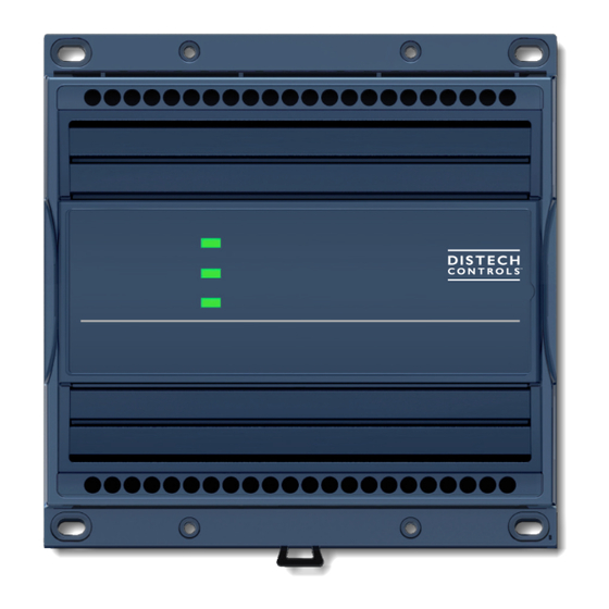
This document describes the hardware installation procedures for the ECx-Light/Blind lighting and shade / sunblind expansion modules for the ECL/ECB-
PTU Series, ECL/ECB-VAV controllers, and ECLYPSE Series controllers.
The Distech Controls ECx-Light/Blind Series expansion modules are designed to complement the main HVAC controller with up to 8 lighting and 8
shade / sunblind commands.
The ECx-Light/Blind Series expansion modules operate off of a separate subnetwork, giving the main HVAC controller the ability to manage additional
controls through its unique subordination system to the master HVAC controller. This optimizes the control possibilities by allowing the global solution
(HVAC controller + expansion modules) to be interpreted as a single device by the network, thereby avoiding unnecessary system overloading.
The ECx-Light/Blind Series product line includes the following modules:
ECx-Light-4 (4 x ON/OFF lights)
ECx-Light-4D (4 x 1-10 V dimming lights)
ECx-Light-4DALI (4 x DALI broadcast buses)
ECx-Blind-4 (4 x High Voltage shades / sunblinds)
ECx-Blind-4LV (4* 24 VDC shades / sunblinds).
ECx-Blind-4SMI (4* High Voltage SMI shades / sunblinds)
ECx-Blind-4SMI-LoVo (4* Low Voltage SMI shades / sunblinds)
ECx-Light-4 and ECx-Light-4D Expansion Modules are available in 3 configurations:
£
WD: 0-240 VAC/DC - Quick-connect
£
ST: 0-240 VAC/DC - Detachable Connectors
£
STP: 0-277 VAC/DC - Detachable Connectors
ECx-Light-4DALI, ECx-Blind-4, ECx-Blind-4LV, ECx-Blind-4SMI, and ECx-Blind-4SMI-LoVo. Expansion Modules are available in 2 configurations:
£
WD: 100-240 VAC - Quick-connect
£
ST: 100-240 VAC - Detachable Connectors
These expansion modules are all built on a similar platform but have different types and number of inputs and outputs.
The ECx-Blind-4SMI modules send position/translation and rotation commands to sunblind motors. Distech Controls is not liable for:
£
The configuration of the SMI motors
£
The motor's operation upon startup
£
Any other behavior that may be defined by the SMI motor manufacturer
General Installation Requirements
For proper installation and subsequent operation of each expansion module, pay special attention to the following recommendations:
£
It is recommended that the product(s) be kept at room temperature for at least 24 hours before installation to allow any condensation that may have
accumulated due to low temperature during shipping/storage to evaporate.
£
Upon unpacking the product, inspect the contents of the carton for shipping damages. Do not install damaged modules.
£
Avoid areas where corroding, deteriorating, or explosive vapors, fumes or gases may be present.
£
Allow for proper clearance around the product's enclosure, and wiring terminals to provide easy access for hardware configuration and mainte-
nance, and to ventilate heat generated by the product.
I n s t a l l a t i o n G u i d e

Advertisement

loading
Need help?

Need help?

Do you have a question about the ECx-Blind Series and is the answer not in the manual?

Questions and answers

Subscribe to Our Youtube Channel

Summary of Contents for Distech Controls ECx-Blind Series

  • Page 1 This document describes the hardware installation procedures for the ECx-Light/Blind lighting and shade / sunblind expansion modules for the ECL/ECB- PTU Series, ECL/ECB-VAV controllers, and ECLYPSE Series controllers. The Distech Controls ECx-Light/Blind Series expansion modules are designed to complement the main HVAC controller with up to 8 lighting and 8 shade / sunblind commands.
  • Page 2 Do not drop the product or subject it to physical shock. £ If the product is used and/or installed in a manner not specified by Distech Controls, the functionality and the protection provided by the product may be impaired. £...
  • Page 3 General Wiring Recommendations Operating, handling, or servicing this product should be ensured by a qualified operator. Turn off the power before any kind of servicing. £ All wiring must comply with electrical wiring diagrams, as well as national and local electrical codes. £...
  • Page 4 Wall-Mounted Installation 1. Use the back plate’s mounting holes to mark the location of any holes that need to be drilled. 2. Drill the required holes (two at least). 3. Clean the surface and mount the expansion module using the appropriate screw types. Figure 2: Wall-mounted expansion module Device Dimensions...
  • Page 5 Power Wiring Model Voltage ECx-Light-4-WD 0-240 VAC/DC; -15%/+10%; 50/60 Hz; Only used to power light outputs. ECx-Light-4-ST The ECx module’s processor and LED lights are powered via the ECx-Light-4D-WD subnetwork. ECx-Light-4D-ST Overvoltage Category II - 2.5 kV ECx-Light-4-STP 0-277 VAC/DC; -15%/+10%; 50/60 Hz; Only used to power light outputs. ECx-Light-4D-STP The ECx module’s processor and LED lights are powered via the subnetwork.
  • Page 6 Operating, handling, or servicing this product should be ensured by a qualified operator. Turn off the power before any kind of servicing. Input Wiring Each expansion module has physical connections for four (4) inputs (marked as DIx for Digital Inputs) that are configured in EC- gfx Program. All input wiring must be connected using the provided detachable connectors.
  • Page 7 Wiring 1-10 V Dimming Lighting Outputs Each dimmer relay output can provide up to 240 VAC (-WD and -ST models) or 277 VAC (-STP models) (same voltage as power supply - 2 A max per output, 6 A maximum in aggregate for each module) and 1-10 V commands (sourcing current / sinking current: +/- 5 mA for each output). The starting current must be kept under 80 A during 20 ms.
  • Page 8 RJ45-RJ45 cable. The Network Guide provides extensive information and requirements to implement this subnetwork. It contains information about network length, cable type, addressing, etc. It can be downloaded from the Distech Controls website. Cable length between each device of the subnetwork (main HVAC controller / ECx-Light/Blind expansion modules / RJ-45 Accessories) should not ex- ceed 30 m (100 ft).
  • Page 9 100 m (328 ft) Maximum Length Subnetwork: Cat 5e Cable with RJ-45 Connectors BLE Enabled Room Light or Sunblind Expansion Module Devices Typical ECLYPSE Controller Figure 14: ECx Subnetwork with BLE enabled room devices The total maximum length of the Subnetwork bus using traditional room devices is 180m (600 ft). 180 m (600 ft) Maximum Length Subnetwork: Cat 5e Cable with RJ-45 Connectors Typical ECB / ECL Controller...
  • Page 10: Table Of Contents

    Termination Figure 16: Setting the ECx-Light/Blind Series’ Subnet ID Address The figure above shows an example of how to set the ECx-Light and ECx-Blind Series’ Subnet ID address DIP switch to 1, while the EOL termination to OFF. Switch Position Expansion module’s Subnet...
  • Page 11 Installed strain relief Tie wraps can then be used to group wires together and attach them securely to the strain relief in an effort to relieve undue tension. Distech Controls recommends using 0.184’’ (4.6 mm) wide tie wraps with a 50 lbs (220 N) tensile strength to attach wires to the strain relief.
  • Page 12 Directive applies to standalone products, for example, products that can function entirely on their own and are not a part of another system or piece of equipment. For this reason Distech Controls products are exempt from the WEEE Directive. Nevertheless, Distech Controls products are marked with the WEEE symbol , indicating devices are not to be thrown away in municipal waste.
  • Page 13 Typical ECx-Light-4 Wiring Diagram Group 3 Group 4 LIGHT 3 LIGHT 4 ECx-Light-4 Load 2A/Output TOTAL 6A max LIGHT 1 LIGHT 2 Un:100-240V Switches 0-240 VAC/DC Power Supply for -WD & -ST models 0-277 VAC/DC Power Supply for -STP models Group 1 Group 2 13 / 21...
  • Page 14: Ecx-Light-4D

    Typical ECx-Light-4D Wiring Diagram Group 3 Group 4 LIGHT 3 LIGHT 4 5mA / 0-10V ECx-Light-4D 5mA / 0-10V Load 2A/Output LIGHT 1 LIGHT 2 TOTAL 6A max Un:100-240V Switches 0-240 VAC/DC Power Supply for -WD & -ST models 0-277 VAC/DC Power Supply for -STP models Group 2 Group 1 14 / 21...
  • Page 15: Ecx-Light-4Dali

    Typical ECx-Light-4DALI Wiring Diagram DALI bus 3 DALI bus 4 LIGHT 3 LIGHT 4 ECx-Light-4DALI Load 5A/Output LIGHT 1 TOTAL 10A max LIGHT 2 Un:100-240V Switches 100-240 VAC Power Supply DALI bus 2 DALI bus 1 15 / 21...
  • Page 16: Ecx-Blind-4

    Typical ECx-Blind-4 Wiring Diagram ECx-Blind-4 Load 2A/Output TOTAL 8A max Un:100-240V Switches 100-240 VAC Power Supply 16 / 21...
  • Page 17: Ecx-Blind-4Smi

    Typical ECx-Blind-4SMI Wiring Diagram I+ I- I+ I- ECx-Blind-4SMI Switches 100-240 VAC Power Supply 17 / 21...
  • Page 18: Ecx-Blind-4Smi-Lovo

    Typical ECx-Blind-4SMI-LoVo Wiring Diagram I+ I- I+ I- ECx-Blind-4SMI-LoVo Switches 100-240 VAC Power Supply 18 / 21...
  • Page 19 Typical ECx-Blind-4LV Wiring Diagram ECx-Blind-4LV Switches 100-240 VAC Power Supply 19 / 21...
  • Page 20 Troubleshooting Guide Issue Symptom Possible Cause Possible Solution Expansion module does not turn on Status LED is turned off There is no power supplied by the Verify that power is being supplied to the controller over the subnetwork, except for controller, and that the controller is running the ECx-Blind-4LV (see dedicated section) properly.
  • Page 21 Specifications subject to change without notice. Distech Controls, the Distech Controls logo, Innovative Solutions for Greener Buildings, EC-Net, ECO-Vue, Allure, and Open-To-Wireless are trademarks of Distech Controls Inc.; LonWorks, LON, and LNS are registered trademarks of Echelon Corporation; BACnet is a registered trademark of ASHRAE; BTL is a registered trademark of the BACnet Manufacturers Association; Niagara Framework is a ®...