Table of Contents
Advertisement
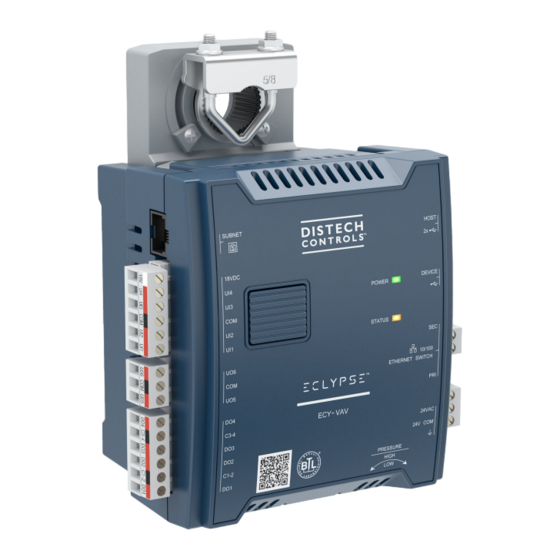
ECLYPSE™ Connected VAV Controller
Figure 1:
ECLYPSE ECY-VAV Controller (left) and ECLYPSE ECY-VAV-PoE Controller (right)
Product Description
This document describes the hardware installation procedures for the ECLYPSE Connected VAV Controller. The ECLYPSE Connected VAV Controller
is designed to control any variable air volume (VAV) box. It supports BACnet/IP communication and is a listed BACnet Building Controller (B-BC). The
Connected VAV Controller comes with an embedded web server that enables web-based VAV application configuration and a visualization interface. It
also features embedded scheduling, alarming, and logging. Control logic and graphic user interface can be customized as required for the application.
The ECLYPSE Connected VAV Controller meets the requirements of VAV zone applications, including: Cooling with Reheat VAV Box & Perimeter Heat-
ing, Parallel Fan VAV Box, Series Fan VAV Box, and Room Pressurization.
This document describes the hardware installation procedures for the following controllers: ECY-VAV and ECY-VAV-PoE. The related terminal covers
are also covered.
General Installation Requirements
For proper installation and subsequent operation of each controller, pay special attention to the following recommendations:
£
Upon unpacking the product, inspect the contents of the carton for shipping damages. Do not install damaged modules.
£
Avoid areas where corroding, deteriorating or explosive vapors, fumes or gases may be present.
£
Ensure the mounting surface can support the controller, DIN rail, and any user-supplied enclosure.
£
When installed in an enclosure, select one that provides sufficient surface area to dissipate the heat generated by the controller and by any other
devices installed in the enclosure. A metal enclosure is preferred. If necessary, provide active cooling for the enclosure.
£
The controller's datasheet specifies the power consumption (amount of heat generated), the operating temperature range, and other environmental
conditions the controller is designed to operate under.
£
Ensure that all equipment is installed according to local, regional, and national regulations.
£
If the controller is used and/or installed in a manner not specified by Distech Controls, the functionality and the protection provided by the controller
may be impaired.
Any type of modification to any Distech Controls product will void the product's warranty.
Take reasonable precautions to prevent electrostatic discharges to the controller when installing, servicing or
operating the controller. Discharge accumulated static electricity by touching one's hand to a well-grounded
object before working with the controller.
I n s t a l l a t i o n G u i d e
Advertisement
Table of Contents

Subscribe to Our Youtube Channel
Related Manuals for Distech Controls ECLYPSE ECY-VAV


Summary of Contents for Distech Controls ECLYPSE ECY-VAV
- Page 1 Ensure that all equipment is installed according to local, regional, and national regulations. £ If the controller is used and/or installed in a manner not specified by Distech Controls, the functionality and the protection provided by the controller may be impaired.
-
Page 2: General Wiring Recommendations
Device Markings (Symbols) Certain markings (symbols) can be found on the controller and are defined as follows: Symbol Description CE marking: the device conforms to the requirements of applicable EC directives. UKCA marking: the device conforms to the requirements of applicable Great Britain regulations. Products must be disposed of at the end of their useful life according to local regulations. - Page 3 £ Always use unshielded cabling with a minimum Category 5 (CAT5) cable for ethernet communications. £ Do not connect the universal inputs, analog/digital outputs or common terminals to earth or chassis ground (unless stated otherwise and/or using shielded Ethernet cable). Module Enclosure Dimensions 5.51 [139.93] 2.75 [69.96]...
- Page 4 10.84 [275.26] 3.70 [94.04] 5.42 [137.63] 1.25 [31.75] 0.40 [10.05] 0.86 [21.95] 6.09 [154.76] ½-inch knockout: Ø 0.875 (7/8) 7.90 [200.61] [Ø 22.23] 4 Positions Front Profile ±0.20 [± 5] 0.55 [13.85] Sliding Grommet Inches [Millimeters] Figure 5: ECY-VAV Series Controllers with Terminal Covers Dimensions (Typical) Configuration Jumper Location and Identification Controllers have the following onsite configurable jumpers.
-
Page 5: Mounting Instructions
The ECY-VAV-PoE Controller must be used with an IEEE 802.3at type 2 certified network switch that can supply 25.5 W at the powered device. Each of the switch’s ports must be configured for static (hardware) power negotiation (that is, Data Link Layer Classification is not supported). By default, the jumpers for this controller are set to the IEEE 802.3at 25.5W position (the factory default setting). - Page 6 4. Connect and wire the controller according to the procedures shown later in this document. VAV Controller Mounting Procedure Mount the controller as follows: 1. The VAV controller comes with the sliding grommet pre-installed. 2. Orient the controller into position on to the damper shaft so that wiring connections are easily accessible. The controller must be fitted onto the shaft such that the base of the controller is parallel to the VAV box (perpendicular to the damper shaft).
- Page 7 VAV Box Damper Minimum : >1.50" >40.00 Shaft Sliding Grommet Opening for Damper Shaft Mounting Screw Inches Millimeters Figure 12: Standard Mounting Method: Mounting a controller on a damper shaft Power Wiring (ECY-VAV Model) Voltage: 24VAC/DC; ± 15%, Class 2 For terminal block connector wiring best practices, see General Wiring Recommendations [pg. 2].
-
Page 8: Daisy-Chain Wiring
Figure 13: Maximum number of ECY-VAV devices on a daisy-chain at evenly spaced intervals Laboratory testing conditions for the above graph are as follows: £ Distance between each VAV is evenly spaced along the entire wire length £ Transformer specification: 100VA (120/24VAC) £... - Page 9 Controller 1 Controller 2 Fuse: 4 A Max. Fast Acting 24V AC 24V AC 24V COM 24V COM 24 VAC Transformer Electrical System Ground – At Transformer Only Figure 14: ECY-VAV Model Power Wiring The following diagram shows the recommended wiring of the ECY-VAV Controller with and without a 3-wire peripheral. This configuration applies either to a daisy-chain configuration or configuration with separate transformers.
-
Page 10: Input Wiring
Input Wiring Input options must be properly configured in EC- gfx Program to ensure correct input readings. The table below shows the controller’s available universal input designation. For terminal block connector wiring best practices, see General Wiring Recommendations [pg. 2]. Inputs can be connected as follows. Before connecting a sensor to the controller, refer to the installation guide of the equipment manufacturer. -
Page 11: Output Wiring
Output Wiring Output options must be properly configured in EC- gfx Program to ensure correct output values. For terminal block connector wiring best practices, see General Wiring Recommendations [pg. 2]. Power may be available from ECY-VAV-PoE controllers to power external loads; see the table below. Outputs can be connected as follows. -
Page 12: Communications Wiring
IP addressing, radio path planning (when the ECLYPSE Wi-Fi Adapter is connected to the con- troller), etc. It can be downloaded from our website. For optimal performance, use Distech Controls category 5e network cable or refer to the ECLYPSE User Guide for cable specifications. -
Page 13: Wireless Connection
Figure 17: ECY-VAV Model Communications Wiring ECY-VAV-PoE Model Wired Connection The ECY-VAV-PoE model uses the network wiring to provide both data connection and the electrical power it needs to operate. The electrical power is provided by the connected network switch. This controller must be used with an IEEE 802.3at certified network switch that is configured such that its de- fault power allocation mode will always provide the maximum available power to the ECY-VAV-PoE device without negotiation. -
Page 14: Configuring The Controller
Configuring the Controller Any of the following methods can be used to connect to the controller’s interface in order to configure it: £ Using the Xpress Network Utility £ Using the controller’s factory-default Hostname in the Web browser £ Using the controller’s IP address in the Web browser Using the Xpress Network Utility The Xpress Network Utility is a software application that runs on a PC that allows you to discover all ECY Series controllers connected to an IP network’s subnetwork or Wi-Fi network and to perform a range of operations on many controllers at once: you can set each controller’s Hostname and IP address,... -
Page 15: Using The Reset Button
Connecting to the Controller’s Configuration Web Interface At the first connection to an ECLYPSE Controller you will be forced to change the password to a strong password for the admin account to protect ac- cess to the controller. In Network Settings, configure the controller’s network parameters so that they are compatible with your network. See the ECLYPSE User Guide for more information about network settings and how to secure the controller. -
Page 16: Maintenance
Cet appareil numérique de la Classe (B) respecte toutes les exigences du Règlement sur le matériel brouilleur du Canada. Specifications subject to change without notice. ECLYPSE, Distech Controls, the Distech Controls logo, EC-Net, Allure, and Allure UNITOUCH are trademarks of Distech Controls Inc. BACnet is a registered trademark of ASHRAE; BTL is a registered ®...
Need help?
Do you have a question about the ECLYPSE ECY-VAV and is the answer not in the manual?
Questions and answers