Advertisement
Table of Contents
- 1 General Wiring Recommendations
- 2 Mounting Instructions
- 3 Wall-Mounted Installation
- 4 Power Wiring
- 5 Input Wiring
- 6 Output Wiring
- 7 Communications Wiring
- 8 Device Addressing
- 9 Wireless Installation
- 10 Connecting the Wireless Receiver
- 11 Maintenance
- 12 North American Emissions Compliance
- 13 Troubleshooting Guide
- Download this manual
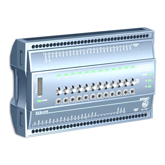
ECB Series BACnet
Figure 1:
Product Description
This document describes the hardware installation procedures for the ECB Series BACnet controllers.
The Distech Controls ECB Series controllers are designed to control and monitor various HVAC equipment such as roof top units, air handling units as
well as chillers, boilers, and central plant applications. Moreover, these controllers are suitable for any lighting control and power measurement applica-
tions. This product line includes the following controllers: ECB‑203, ECB‑300, ECB‑400 Series, ECB‑600 Series.
For controllers equipped with an operator interface (ECB-x50 models), refer to the ECL‑x50 and ECB‑x50 Series Controller User Guide for how to use
the this interface.
The ECB‑600 Series are compatible with the IO Extension Module product line, which includes the following modules: ECx‑400, ECx‑410, and ECx-420
(refer to the ECx‑400 series IO Extension Module Hardware Installation Guide).
Each controller uses the BACnet
This document describes the hardware installation procedures for the following controllers: ECB‑203, ECB‑300, ECB‑400 Series, and ECB‑600 Series
controllers only.
£
These controllers are all built on a similar platform, but have different numbers of inputs and outputs. Moreover,
each individual model has different amounts of digital and/or universal outputs. For more information on the
specific layout and functionality of each controller, please refer to their individual datasheets.
£
The following controllers are housed in small enclosures: ECB‑203 Series and ECB‑300 Series.
£
The following controllers are housed in large enclosures: ECB‑400 Series and ECB‑600 Series.
General Installation Requirements
For proper installation and subsequent operation of the device, pay special attention to the following recommendations:
£
It is recommended that the controller(s) be kept at room temperature for at least 24 hours before installation to allow any condensation that may
have accumulated due to low temperature during shipping/storage to evaporate.
£
Upon unpacking, inspect the contents of the carton for shipping damages. Do not install a damaged device.
£
The device is designed to operate under environmental conditions that are specified in its datasheet.
£
Ensure proper ventilation of the device and avoid areas where corroding, deteriorating or explosive vapors, fumes or gases may be present.
£
Allow for proper clearance around the device's enclosure and wiring terminals to provide easy access for hardware configuration and maintenance.
£
When installing in an enclosure, select one that provides sufficient surface area to dissipate any heat generated by the device and by any other de-
vices installed in the enclosure. A metal enclosure is preferred. If necessary, provide active cooling for the enclosure.
£
Orient the controller with the ventilation slots and power supply/output terminal block connectors towards the top to permit proper heat dissipation.
£
The device's plastic enclosure has a back plate that is separable from the front plate allowing the back plates (with the connectors) to be shipped di-
rectly to the installation site while all the engineering is done in the office.
£
The device's datasheet specifies the power consumption (amount of heat generated), the operating temperature range, and other environmental
conditions the device is designed to operate under.
£
Ensure that all equipment is installed according to local, regional, and national regulations.
£
Do not drop the device or subject it to physical shock.
£
If the device is used and/or installed in a manner not specified by Distech Controls, the functionality and the protection provided by the device may
be impaired.
From left to right: ECB-650 with operator interface, ECB-410 with HOA, ECB-203
®
MS/TP LAN communication protocol.
H a r d w a r e I n s t a l l a t i o n G u i d e
®
Controllers
Advertisement
Table of Contents

Related Manuals for Distech Controls ECB Series


Summary of Contents for Distech Controls ECB Series
- Page 1 This document describes the hardware installation procedures for the ECB Series BACnet controllers. The Distech Controls ECB Series controllers are designed to control and monitor various HVAC equipment such as roof top units, air handling units as well as chillers, boilers, and central plant applications. Moreover, these controllers are suitable for any lighting control and power measurement applica- tions.
-
Page 2: General Wiring Recommendations
Any type of modification to any Distech Controls product will void the product’s warranty Take special care to keep the front and back plate aligned when separating and joining them. Before installation of the Wireless Receiver, verify that local communication regulations allow the installation of wireless devices and available frequencies to be supported in your area. - Page 3 Controller Dimensions & Components Figure 2: Rear view of large enclosure Figure 3: Rear view of small enclosure Figure 4: Side view of large and small enclosure 3 / 20...
-
Page 4: Mounting Instructions
Mounting Instructions The controllers can be mounted on a DIN rail to speed up the installation procedure. They are also equipped with two mounting holes 0.25” x 0.165” (6.35mm x 4.191mm). The controllers can be mounted in a panel or on a wall by using appropriate screw types (use sheet metal, thread forming, or self-tapping screws accordingly). -
Page 5: Power Wiring
Power Wiring Voltage: 24VAC/DC; ± 15%, Class 2 This is a Class 2 Product. Use a Class 2 transformer only (rated at 100VA or less at 24VAC) to power the controller(s). The Network Guide provides extensive information and requirements for powering a controller that uses a BACnet network for communications. It can be downloaded from our website. - Page 6 Jumper Identification and Configuration Controllers have the following onsite configurable jumpers. Wireless Port BACnet MS / TP Network EOL Termination EOL Off EOL On (Disabled)* (Enabled) Subnet Net Port Port * Factory- default positions Figure 8: ECB-203 Controller Jumper Locations Wireless Port Universal Outputs (UO) 0- 10V / 0- 20 mA Select 0- 10V...
-
Page 7: Input Wiring
Input Wiring Before connecting a sensor to the controller, refer to the installation guide of the equipment manufacturer. £ For a wire length less than 75’ (23m), either a shielded or unshielded 18AWG wire may be used. £ For a wire up to 200’ (61m) long, a shielded 18AWG wire is recommended. £... - Page 8 Sensor Input Type Input Connection Diagram ECB‑300, ECB‑400, and ECB‑600 Series: Jumper To Analog- £ 0 to 20mA input used with a 2-wire, 0 to 20mA sensor powered by the controller’s internal Setting 0-10V To-Digital 15VDC power supply. +15VDC Converter 0-20mA £...
-
Page 9: Output Wiring
Output Wiring Before connecting an output device (actuator, relay, etc.) to the controller, refer to the datasheet and installation guide of the equipment manufacturer. £ For a wire length less than 75’ (23m) long, either a shielded or unshielded 18AWG wire may be used. £... -
Page 10: Communications Wiring
For optimal performance, use Distech Controls 24 AWG (0.65 mm) stranded, twisted pair shielded cable or refer to the Network Guide for cable specification. The BACnet MS/TP com- munication wire is polarity sensitive and the only acceptable topology is to daisy-chain the cable from one controller to the next. -
Page 11: Device Addressing
First and last daisy-chained device: - EOL Jumpers are ON All other Devices: : - EOL Jumpers are OFF Typical BACnet Device Typical BACnet Device Typical EC-BOS Device EOL ON: For the EC-BOS EOL ON EOL OFF as the first or last daisy chained device: - OPTIONALLY set the EOL jumper internally... - Page 12 The Device Instance can be changed once the controller has been commissioned through the network management software interface. The Device Instance can be changed once the controller has been commissioned through the network management software interface or through the color LCD screen’s Settings menu (when equipped). Temporary Network Access To temporarily access the BACnet MS/TP LAN for commissioning and maintenance purposes, connect a BACnet MS/TP Adaptor to the NET PORT au- dio plug.
- Page 13 9. Press and hold the Menu button for 5 seconds to exit the configuration menu. The an Allure EC-Smart-Vue Series Communicating Sensor can now be used to go from one ECB series controller to the next for commissioning pur- poses.
- Page 14 Commissioning ECB-Series Controllers When using an Allure EC-Smart-Vue Series Communicating Sensor for commissioning ECB Series controllers (the DIP switch located on the faceplate is set to 0 (all off) and before code is downloaded to the controller from EC- gfx Program ), connect an Allure EC-Smart-Vue Series Communicating Sensor to the controller with its Subnet ID set to 1.
- Page 15 Setting the BAUD Rate (optional – ECB series controllers only) By default, the BAUD rate for the controller is set to automatically detect the current communication BAUD rate of the connected BACnet MS/TP network (AUTO). This is the preferred setting for a controller. However, at least one controller on the BACnet MS/TP network data bus must have its BAUD rate set.
-
Page 16: Wireless Installation
Wireless Installation When connected to a Wireless Receiver, controllers can receive input signals from a wide selection of wireless devices. Compatible wireless devices in- clude temperature sensors, duct sensors, window/door contacts and light switches. These devices are easy to install, and can be mounted on a wide range of building materials. -
Page 17: Maintenance
Directive applies to standalone products, for example, products that can function entirely on their own and are not a part of another system or piece of equipment. For this reason Distech Controls products are exempt from the WEEE Directive. Nevertheless, Distech Controls products are marked with the WEEE symbol , indicating devices are not to be thrown away in municipal waste. - Page 18 Typical Air Handling Unit Application Wiring Diagram Supply Return Heat Cool Damper Humidifier Starter Starter Fuse: 4A Max. 0-10 0-10 0-10 0-10 Transformer Fast Acting 24VAC Electrical System Ground ECB-400 Data Bus Shields: Twist together and Isolate with electrical tape Back of an Allure EC-Smart-Vue * 249 ohm resistor built-in for inputs configured as 0-20mA...
-
Page 19: Troubleshooting Guide
Troubleshooting Guide Controller is powered but does not turn on Fuse has blown Disconnect the power. Check the fuse integrity. Reconnect the power. Power supply polarity Verify that consistent polarity is maintained between all controllers and the transformer. Ensure that the 24VCOM terminal of each controller is connected to the same terminal on the secondary side of the transformer. - Page 20 ©, Distech Controls Inc., 2010 - 2019. All rights reserved. Images are simulated. While all efforts have been made to verify the accuracy of information in this manual, Distech Controls is not responsible for damages or claims arising from the use of this manual.
Need help?
Do you have a question about the ECB Series and is the answer not in the manual?
Questions and answers