Table of Contents
Advertisement
Advertisement
Table of Contents
Troubleshooting

Related Manuals for Nice 7251


Summary of Contents for Nice 7251
- Page 1 Installation and Programming Manual 7251/7351 Slide Vehicular pad or post-mount slide gate operator with 1050 control board 7251 post mount with 1050 control board 7351 pad mount with 1050 control board www.ApolloGateOpeners.com | (800) 878-7829 | Sales@ApolloGateOpeners.com...
-
Page 2: Table Of Contents
7251 / 7351 Slide Gate Operator INSTALLATION AND PROGRAMMING MANUAL CONTENTS LIST OF INSTRUCTIONS................2 SECTION 1: 7251 / 7351 SLIDE GATE OPERATOR OVERVIEW....3 1.1 1050 CONTROL BOARD FEATURES............3 SECTION 2: PARTS IDENTIFICATION............5 SECTION 3: SAFETY AND UL325 USAGE CLASSES........6 SECTION 4: INSTALLATION SAFETY............11 SECTION 5: TOOLS &... -
Page 3: Section 1: 7251 / 7351 Slide Gate Operator Overview
INSTALLATION AND PROGRAMMING MANUAL SECTION 1: 7251 / 7351 SLIDE GATE OPERATOR OVERVIEW Congratulations on selecting a Nice series gate operator using the 1050 control board. With proper selection, system design, installation and maintenance this operator should provide years of reliable operation. - Page 4 7251 / 7351 Slide Gate Operator INSTALLATION AND PROGRAMMING MANUAL 7251 / 7351 SYSTEM SPECIFICATIONS 7251 - POST MOUNT 7351 - PAD MOUNT MODEL 22 x 22 x 15.5 inches 20.5 x 26.5 x 18 inches ENCLOSURE (W x H x D) (56 x 56 x 39.4 cm)
-
Page 5: Section 2: Parts Identification
7251 / 7351 Slide Gate Operator INSTALLATION AND PROGRAMMING MANUAL SECTION 2: PARTS IDENTIFICATION 7251 / 7351 CONTROL BOX PARTS LIST PART# DESCRIPTION 7251 or 7351 Post mount or pad mount control box w/ cover OXI/A Multi-channel plug-in receiver 273C... -
Page 6: Section 3: Safety And Ul325 Usage Classes
Some operators are restricted in their usage application. All Nice USA operators are approved for use in all four UL325 Usage Classes. Appropriate Usage Classes are shown in the Specifications. - Page 7 • guarding is supplied for exposed rollers; • When utilizing a Nice 936 or 1050 board, a maximum of 8 entrapment protection devices (6 BlueBUS and 2 pulse outputs may be connected.
- Page 8 7251 / 7351 Slide Gate Operator INSTALLATION AND PROGRAMMING MANUAL CONTACT SENSORS (EDGE) etacheD ates For a gate operator utilizing a contact sensor (Edge): Gates shall be designed, constructed and installed to not fall • One or more contact sensors shall be located where...
- Page 9 7251 / 7351 Slide Gate Operator INSTALLATION AND PROGRAMMING MANUAL i, ii, iii h Exposed Rollers Lass orizontaL WinG ates All weight bearing exposed rollers 8 feet (2.44 m), or less, The following provisions shall apply to Class I, Class II, and...
- Page 10 Only the following external sensors have been evaluated and c. Potential entrapment zones are shown in INSTRUCTION tested with Nice 1050 control boards and are approved to be 6, IMAGE 6-1 & for slide gates, but there may be other...
-
Page 11: Section 4: Installation Safety
Chain breaking tool 5.1 CONTROL BOX POWER REQUIREMENTS The following are required to power the 7251 or 7351 control box: • 12VDC battery to power the control board • An AC-to-DC fully automatic charger, a 12-30 VDC power source, and/or solar panel to charge the battery. -
Page 12: Section 6: 7251 - Post-Mount Installation
7251 / 7351 Slide Gate Operator INSTALLATION AND PROGRAMMING MANUAL SECTION 6: 7251 - POST-MOUNT INSTALLATION 7251: INSTALL POST-MOUNT CONTROL BOX 1. Secure two 3” posts in the ground as necessary for your type of soil conditions and building codes per IMAGE 1A-1. - Page 13 7251 / 7351 Slide Gate Operator INSTALLATION AND PROGRAMMING MANUAL 7251: MOUNT CHAIN BRACKETS TO GATE FRAME 1. Put the gate in the center of travel of the opening (IMAGE 2A-1). The gate should remain in this position while the chain is attached to the operator.
- Page 14 7251 / 7351 Slide Gate Operator INSTALLATION AND PROGRAMMING MANUAL 7251: ROUTE CHAIN AND CONNECT CHAIN BOLT 1. Route chain through sprockets as shown in IMAGE 3A-1. Make sure chain is level when attached to the chain brackets. Chain should be aligned with all sprockets.
-
Page 15: Section 7: 7351 - Pad-Mount Installation
7251 / 7351 Slide Gate Operator INSTALLATION AND PROGRAMMING MANUAL SECTION 7: 7351 - PAD-MOUNT INSTALLATION 7351: INSTALL PAD-MOUNT CONTROL BOX 1. Fabricate a concrete structure sufficient to stabilize and mount the operator. Consult local building codes to build a pad that meets or is sufficient for the soil type and climate and capable of supporting the loads imposed by the operator during operation. - Page 16 7251 / 7351 Slide Gate Operator INSTALLATION AND PROGRAMMING MANUAL 7351: MOUNT CHAIN BRACKETS TO GATE FRAME 1. Put the gate in the center of travel of the opening (IMAGE 2B-1). The gate should remain in this position while the chain is attached to the operator.
- Page 17 7251 / 7351 Slide Gate Operator INSTALLATION AND PROGRAMMING MANUAL 7351: ROUTE CHAIN AND CONNECT CHAIN BOLT 1. Route chain through sprockets as shown in IMAGE 3B-1. Make sure chain is level when attached to the chain brackets. Chain should be aligned with all sprockets.
-
Page 18: Section 8: Control Board & Motor Wiring
7251 / 7351 Slide Gate Operator INSTALLATION AND PROGRAMMING MANUAL SECTION 8: CONTROL BOARD & MOTOR WIRING MOUNT BATTERY IN CONTROL BOX CHASSIS Place battery in the operator chassis as shown below. For 7351, position battery terminals toward opening. 7251... -
Page 19: Instruction 5A: 7351 - Wiring Motor To Control Board
If gate opens to left (from secure side) refer to IMAGE 5A-1 and ensure 5-pin/3-pin connectors are plugged into the “Motor 1” connectors (IMAGE 5A-1) and wired as shown. 7251 - RIGHT OPENING SINGLE GATE WIRING (DEFAULT): If gate opens to right (from secure side) refer to IMAGE 5A-2, rewire connectors to match illustration, and plug 5-pin/3-pin connectors into the “Motor 1”... - Page 20 7251 / 7351 Slide Gate Operator INSTALLATION AND PROGRAMMING MANUAL 5A: 7251 - CONTROL BOARD WIRING (CONT.) DUAL GATE OPEN LEFT/RIGHT NOTE: Gate view is from secure side. 7251 DUAL MOTOR GREEN WHITE 7251 7251 WHITE ORANGE LIMITS LIMITS LEFT-HAND...
-
Page 21: Instruction 5B: 7251 - Wiring Motor To Control Board
7251 / 7351 Slide Gate Operator INSTALLATION AND PROGRAMMING MANUAL 7351 - WIRE MOTOR TO CONTROL BOARD 1050 CONTROL BOARD MOTOR CONNECTIONS 1050 CONTROL BOARD 7351 - LEFT OPENING SINGLE GATE WIRING (DEFAULT): If gate opens to left (from secure side) refer to IMAGE 5B-1 and ensure 5-pin/3-pin connectors are plugged into the “Motor 1”... - Page 22 7251 / 7351 Slide Gate Operator INSTALLATION AND PROGRAMMING MANUAL 5B: 7351 - CONTROL BOARD WIRING (CONT.) DUAL GATE OPEN LEFT/RIGHT NOTE: Gate view is from secure side. 7351 DUAL MOTOR GREEN ORANGE 7351 7351 LIMITS ORANGE WHITE LIMITS RIGHT-HAND...
-
Page 23: Section 9: Blue Bus Photo Eye Installation
7251 / 7351 Slide Gate Operator INSTALLATION AND PROGRAMMING MANUAL SECTION 9: BLUE BUS PHOTO EYE INSTALLATION DETERMINE BLUEBUS PHOTO EYE LOCATIONS See below for suggestions of photo eye positioning for your gate configuration. NOTE: Name designations in IMAGE 6-1 (P1, P2, etc.) are arbitrary designations used to indicate jumper settings for each photo eye location. -
Page 24: Instruction 7: Prepare Bluebus Photo Eyes For Install
7251 / 7351 Slide Gate Operator INSTALLATION AND PROGRAMMING MANUAL IMPORTANT! The 1050 control board will not operate without at least two monitored and functioning safety devices connected to the control board. Before power is connected to the control board, install either the BlueBUS through-beam photo eyes per the instructions below, an alternative photo eye, such as a reflective photo eye (per manufacturers instructions), or both, before attempting to apply power to the control board. -
Page 25: Instruction 8: Install & Wire Bluebus Photo Eyes
7251 / 7351 Slide Gate Operator INSTALLATION AND PROGRAMMING MANUAL INSTALL & WIRE BLUEBUS PHOTO EYES 1. Ensure alignment between receiver and transmitter brackets (H), then affix both to selected locations with included screws (I). IMPORTANT! If using the model EPMB/A non-adjustable... -
Page 26: Instruction 9: Connect Bluebus Photo Eyes To Board
7251 / 7351 Slide Gate Operator INSTALLATION AND PROGRAMMING MANUAL CONNECT BLUEBUS PHOTO EYES TO BOARD Install through beam photo eye bus wires (no polarity) into 2-pin BlueBUS connector on control board (IMAGE 9-1). If an alternative photo eye is used, follow installation instructions included with it. -
Page 27: Section 10: Power Options And Wiring
Nice recommends an 8 foot copper rod driven all the way into the ground with a copper clamp and 12ga GROUND copper wire minimum. -
Page 28: High Voltage Wire Gauge Requirements
7251 / 7351 Slide Gate Operator INSTALLATION AND PROGRAMMING MANUAL IMPORTANT! Power should not be applied to the control board until after the photo eyes have been installed and wired to the control board. Power is applied in INSTRUCTIONS 12, 13, and/or 14. -
Page 29: Instruction 12: Main Dc Power - Input Connections
LED will illuminate above the connector. For 30W solar panels and above, an external regulator must be used. Nice offers a regulator (P/N SG-4) for this purpose. See INSTRUCTION 14B for installation instructions for the SG-4 regulator. -
Page 30: Instruction 13B: Solar Panel Connection - 30W & Above
Solar panels of 30W and above must be connected to an outboard regulator which, in turn, then connects to the battery to enable battery charging. Nice offers a regulator (P/N SG-4) for this purpose. For regulators sourced elsewhere, follow the manufacturers instructions when installing. Install and wire the 30W and above solar panels and SG-4 regulator as follows: 1. -
Page 31: Instruction 14: Power Up Control Board
(Open or Close) indicating the board is ready to ‘learn” the gate limits, and you may proceed to INSTRUCTION 16. 8. If safety devices provided in the kit are determined to be defective, contact Nice technical support. -
Page 32: Instruction 15: Select Control Board Standby Mode
7251 / 7351 Slide Gate Operator INSTALLATION AND PROGRAMMING MANUAL SELECT CONTROL BOARD STANDBY MODE NOTES: IMPORTANT! W h e n d i s p l a y i s O F F For SOLAR APPLICATIONS - Turn the Standby Mode ON. -
Page 33: Section 12: Adjusting Gate Open/Close Limits
7251 / 7351 Slide Gate Operator INSTALLATION AND PROGRAMMING MANUAL SECTION 12: ADJUSTING GATE OPEN/CLOSE LIMITS NOTE: Until the control board has “LEARNED” the open/close limits, the OPEN and CLOSE buttons must be pressed and HELD DOWN to operate the gate(s). Once limits are learned by the control board, it will take only a single press (and release) to fully open or close the gate. -
Page 34: Instruction 16: Gate Limit Learning Procedure
7251 / 7351 Slide Gate Operator INSTALLATION AND PROGRAMMING MANUAL GATE LIMIT LEARNING PROCEDURE 1. Control board should be powered. If not, apply power per INSTRUCTION GATE WEIGHT TABLE 12, 13, and/or 14. Results in quicker acceleration/ 2. If a dual gate system, ensure ONLY ONE of the motor harnesses is deceleration, lower connected at a time and ONLY to the MOTOR 1 connectors. - Page 35 7251 / 7351 Slide Gate Operator INSTALLATION AND PROGRAMMING MANUAL 16: GATE LIMIT LEARNING PROCEDURE (CONT.) (Continued) 6. Push and hold the OPEN button on Control Board until gate reaches the fully intended open position. 7. OPEN LIMIT ADJUST: • If gate opens to left (viewing from secure side), adjust left hand knob of limit assembly (IMAGE 17- 5) until the GREEN LED illuminates on control board (IMAGE 17-4).
- Page 36 7251 / 7351 Slide Gate Operator INSTALLATION AND PROGRAMMING MANUAL 16: GATE LIMIT LEARNING PROCEDURE (CONT.) (Continued) • If gate closes to right (viewing from secure side), adjust right hand knob of limit assembly (IMAGE 17-5) until the RED LED illuminates on control board (IMAGE 17-4).
-
Page 37: Section 13: Final Assembly & Programming
7251 / 7351 Slide Gate Operator INSTALLATION AND PROGRAMMING MANUAL SECTION 13: FINAL ASSEMBLY & PROGRAMMING BLUEBUS PHOTO EYE STATUS & TROUBLESHOOTING Once BlueBUS photo eyes are recognized by the control board, the photo eye LED behavior should be checked and adjustments made as follows: 1. -
Page 38: Instruction 18: Bluebus Photo Eye Alignment
7251 / 7351 Slide Gate Operator INSTALLATION AND PROGRAMMING MANUAL BLUEBUS PHOTO EYE ALIGNMENT If adjustment of photo eye alignment is necessary, refer to the following instructions: NOTES: Photo eye testing is described in INSTRUCTION 20. Adjustment instructions apply only to EPMOB/A and EPLOB/A models. EPMB/A model is not adjustable, and must be adjusted using mechanical means left up to the installer. -
Page 39: Instruction 19: Bluebus Photo Eye Testing
7251 / 7351 Slide Gate Operator INSTALLATION AND PROGRAMMING MANUAL BLUEBUS PHOTO EYE TESTING Photo eyes must be tested after power is applied to the control board to ensure proper operation: 1. Apply power to control board and ensure BlueBUS devices are detected and functioning. -
Page 40: Instruction 21: Installing The Audio Alarm
7251 / 7351 Slide Gate Operator INSTALLATION AND PROGRAMMING MANUAL INSTALLING THE AUDIO ALARM IMPORTANT! The installer MUST connect the included audio alarm per these instructions. Installing the audio alarm is REQUIRED for UL325 compliance. The audio alarm (siren) included in the kit must be connected to the 1050 control board to provide an audible alarm to indicate a hard shutdown of the system, which is triggered by two consecutive entrapment events. -
Page 41: Instruction 22: Assigning New Remote Control
LED lights up on the side of the receiver, then release the button. 2. Within 10 seconds, press and hold any key on the Nice remote control until the LED in the Nice receiver blinks green 3 times, indicating that the remote control is programmed to control the receiver. -
Page 42: Instruction 23: Deleting Single Remote Control
1. Press and hold the button on the side of the Nice receiver (on 1050 board) until the LED on the Nice receiver illuminates green and keep the button pressed. The LED will illuminate after approximately 4 seconds. -
Page 43: Section 14: Programming And Controls
7251 / 7351 Slide Gate Operator INSTALLATION AND PROGRAMMING MANUAL SECTION 14: PROGRAMMING AND CONTROLS This section describes the navigation, menu, and programming controls for the 1050 control board. See FIGURE 14-1 (below) and TABLE 25-1 (next page) for identification of the controls used to navigate and select various options, and the following pages for descriptions and diagrams of menus and the options available for programming. -
Page 44: Instruction 25: Control Board Menu Navigation
7251 / 7351 Slide Gate Operator INSTALLATION AND PROGRAMMING MANUAL CONTROL BOARD MENU NAVIGATION Refer to Figure 14-1 on previous page for image of 1050 control board layout, LED indicators, and controls. Menus and parameters are accessed and selected by pressing the buttons on the 1050 control... - Page 45 7251 / 7351 Slide Gate Operator INSTALLATION AND PROGRAMMING MANUAL FORCE BUTTON FORCE BUTTON MENU: Amount of force needed to cause the gate to stop FORCE and reverse when hitting an obstacle. (min-max FORCE • STATIC: Set sensitivity to constant force on a sensitivity) 1.Static...
- Page 46 7251 / 7351 Slide Gate Operator INSTALLATION AND PROGRAMMING MANUAL DELAY BUTTON DELAY 90 SEC. DELAY 1. Auto Close 0 SEC. Press 5 SEC. DELAY 2. Slave :0.0 0 SEC. 5 SEC. DELAY 3. Lamp :0.0 0 SEC. 5 SEC.
- Page 47 7251 / 7351 Slide Gate Operator INSTALLATION AND PROGRAMMING MANUAL FUNCTION BUTTON > Learn LEARN Average GATE WEIGHT TABLE Results in quicker acceleration/ LEARN LEARN Heavy Average deceleration, lower (more Light sensitive) FORCE settings, and higher LEARN LEARN SLOWDOWN Average Average speed.
- Page 48 7251 / 7351 Slide Gate Operator INSTALLATION AND PROGRAMMING MANUAL FUNCTION BUTTON > Positions FUNCTIONS>POSITIONS MENU: Sets points in the gate open, close, and 100% partial cycles at which deceleration SlowDown Open 100% 1. Learn occurs. (see previous page) • SLOW DOWN - OPEN: Sets the...
- Page 49 7251 / 7351 Slide Gate Operator INSTALLATION AND PROGRAMMING MANUAL FUNCTION BUTTON > Auxiliary IO (Cont.) FUNCTION>AUXILIARY OUTPUTS MENU: FUNCTION>AUXILIARY INPUTS MENU: Auxiliary outputs OUT1 (1,2,3,) and OUT2 (4,5,6,) can be The auxiliary inputs IN1(16) and IN2 (18) can be programmed with one of these options.
- Page 50 7251 / 7351 Slide Gate Operator INSTALLATION AND PROGRAMMING MANUAL FUNCTION BUTTON > Radio Ch. CH2 - CH15 Togle&Latch Hold to open Step H Stop Cls&Unlock Partial 1 3. Auxiliary IO Opn&Unlock Partial Radio Ch (see previous page) Close&Lock Step Togler&Latch...
- Page 51 7251 / 7351 Slide Gate Operator INSTALLATION AND PROGRAMMING MANUAL FUNCTION BUTTON > Timers Timer 2 Second Timer 2 Minute Timer 2 Timer 2 Timer 2 Hour 00:00:00 Hour Timer 1 Second 4. Radio Ch Timer 1 Minute (see previous page)
- Page 52 7251 / 7351 Slide Gate Operator INSTALLATION AND PROGRAMMING MANUAL FUNCTION BUTTON / Events NOTE: See INSTRUCTIONS 27 and 28 (next page) for specific instructions for programming and suspending events. Wed-Sun TOGGLE Tue Off (blinking) ON/OFF TOGGLE Mon Off (blinking)
-
Page 53: Instruction 26: Event Programming Instructions
7251 / 7351 Slide Gate Operator INSTALLATION AND PROGRAMMING MANUAL EVENT PROGRAMMING INSTRUCTIONS To PROGRAM weekly events EV1 through EV8, perform the following steps: 1. Ensure time and date are set correctly. See Function/Display Menu for how to set time/date. - Page 54 7251 / 7351 Slide Gate Operator INSTALLATION AND PROGRAMMING MANUAL FUNCTION BUTTON / Charger 6. Events (see previous page) FUNCTION Charger Charger 7. Charger 1.5A Charger 8. Standby Max I = 1.50A (see below) 0.10A FUNCTION>CHARGER MENU: 30 Sec. Charger Built-in battery charger is for use with backup battery.
- Page 55 7251 / 7351 Slide Gate Operator INSTALLATION AND PROGRAMMING MANUAL FUNCTION BUTTON / Adv. Settings 8. Standby (see previous page English Language Language English English (blink) English FUNCTION 9. Adv. Settings 24 Hour Clock Clock (blinking) 12 Hour 10. Default (see next page)
- Page 56 7251 / 7351 Slide Gate Operator INSTALLATION AND PROGRAMMING MANUAL FUNCTION BUTTON / Adv. Settings (Cont.) From Inputs Analog (see previous page) Both UL Input Open Analog Analog Both (blinking) Close UL Input Digital NO (blink) UL Input Digital Digital NO...
- Page 57 7251 / 7351 Slide Gate Operator INSTALLATION AND PROGRAMMING MANUAL FUNCTION BUTTON / Defaults 9. Adv. Settings (see previous page) System Set Default to Defaults FUNCTION 10. Default System Radio Chan. Set 11. Gate Sync Default to Defaults (see next page) Radio Ch FUNCTION>DEFAULT MENU:...
- Page 58 7251 / 7351 Slide Gate Operator INSTALLATION AND PROGRAMMING MANUAL DISPLAY BUTTON: For selecting certain information for viewing in the LCD display. Display PRESS DISPLAY 1. ESC DISPLAY Nice/Apollo DISPLAY BUTTON MENU: 2. Info Board 1050 Info: Displays the manufacturer name, prod- uct name/model, software versions, and serial number.
- Page 59 7251 / 7351 Slide Gate Operator INSTALLATION AND PROGRAMMING MANUAL DISPLAY BUTTON (CONT.): Continued from last page DISPLAY SUN VOLT DISPLAY BUTTON MENU (CONT.): 6. Sun Volt 24.6V Sun Volt: Displays the solar panel input voltage in volts DC. Motor Volt: Displays the voltage at the motor in volts DC.
-
Page 60: Control Board Error Messages & Troubleshooting
7251 / 7351 Slide Gate Operator INSTALLATION AND PROGRAMMING MANUAL 14.1 CONTROL BOARD ERROR MESSAGES & TROUBLESHOOTING CONTROL BOARD ERROR MESSAGES AND TROUBLESHOOTING DISPLAY REASON POSSIBLE CAUSE(S) Actuator connected to Motor 1 has a brief current Check for obstruction in gate path or degraded Dynamic M1 spike and tripped Type A sensor. -
Page 61: Section 15: Accessory Connections
7251 / 7351 Slide Gate Operator INSTALLATION AND PROGRAMMING MANUAL SECTION 15: ACCESSORY CONNECTIONS This section describes the accessory functions, connections, and wiring for the 1050 control board. See FIGURE 15-1 (below) for a visual representation of all the accessory inputs and outputs, and the following pages for a description of I/O functions and pin designations. -
Page 62: Output Connectors
7251 / 7351 Slide Gate Operator INSTALLATION AND PROGRAMMING MANUAL 15.1 OUTPUT CONNECTORS OUT 1 / OUT 2 (1-6): Individual, isolated relays provide dry contacts for switching accessories based on programming of the “Auxiliary IO” function. These outputs are programmed in the “FUNCTION / Auxiliary I/O” menu. - Page 63 7251 / 7351 Slide Gate Operator INSTALLATION AND PROGRAMMING MANUAL LAMP (12-13): • Provides fused power (1.85A max) to drive a flashing warning lamp to indicate gate operation. • This output is active when the gate is operating (Opening and Closing).
-
Page 64: Input Connectors
7251 / 7351 Slide Gate Operator INSTALLATION AND PROGRAMMING MANUAL 15.2 INPUT CONNECTORS AUXILIARY INPUTS 1 & 2 (16-19): • These digital inputs may be connected to the digital outputs of accessories and programmed to activate or control the gate operator in a number of different modes. - Page 65 7251 / 7351 Slide Gate Operator INSTALLATION AND PROGRAMMING MANUAL EDGE INPUT (28-29): • The EDGE input may be configured as a monitored ANALOG input, or DIGITAL (NC or NO) input. • The EDGE sensor input is intended for ANSI/UL 325 listed gate edge sensors to protect against entrapment and hazardous pinch points along the moving edge of the closing gate.
- Page 66 7251 / 7351 Slide Gate Operator INSTALLATION AND PROGRAMMING MANUAL GUARD STATION INPUT (34-37): • With the Guard Station switches installed, the user can operate the gate by pushing the respective buttons for the command that is desired. • Gate Open and Close are controlled by NORMALLY OPEN (NO) and Stop is controlled by NORMALLY CLOSED (NC) momentary switches.
-
Page 67: Communications Buses
OVIEW CONTROLLER: • The Oview controller is an optional programming and diagnostic tool, which plugs directly into the 1050 control board using an RJ45 network cable and is part of the Nice “Opera” control system. • The Oview controller can be used in “stand-alone” mode via its front-panel keypad. -
Page 68: Section 16: Emergency Vehicle Access
SECTION 16: EMERGENCY VEHICLE ACCESS The 7251 and 7351 gate operators both feature a quick release system designed to allow the gate to be manually opened under different operating conditions (see next page). However, it is the responsibility of the gate owner to make sure that the gate operating system is compliant with all local codes and regulations and that access for emergency vehicles is assured. -
Page 69: Section 17: Manual Quick Release Operation
CAUTION! BEFORE MANUALLY OPENING THE GATE, VERIFY THAT POWER HAS BEEN SHUT OFF. QUICK RELEASE ASSEMBLY FIGURE 17-1: 7251 (L) AND 7351 (R) QUICK RELEASE ASSEMBLY LOCATION LOCK PINS KNURLED KNOB PULL KNURLED KNOB OUT AND TWIST A HALF TURN... -
Page 70: Section 18: Appendix
7251 / 7351 Slide Gate Operator INSTALLATION AND PROGRAMMING MANUAL SECTION 18: APPENDIX CALCULATING SOLAR REQUIREMENTS CALCULATING SOLAR REQUIREMENTS 1. Estimate the gate traffic measured in open/close cycles per TABLE 25-1. TABLE 28-1: SOLAR PANEL WATT/CYCLE CHART DAILY CYCLES 1-10... -
Page 71: Maintenance Schedule
7251 / 7351 Slide Gate Operator INSTALLATION AND PROGRAMMING MANUAL 18.1 MAINTENANCE SCHEDULE MAINTENANCE SCHEDULE Component Maintenance Action Annually Months Activate the primary (inherent) reverse system by blocking the gate with a solid object. The gate should reverse momentarily then stop. -
Page 72: System Troubleshooting
7251 / 7351 Slide Gate Operator INSTALLATION AND PROGRAMMING MANUAL 18.2 SYSTEM TROUBLESHOOTING SYSTEM TROUBLESHOOTING Problem Possible Solution • Check the UL/Edge input on the gate controller. Gate opens a short • Ensure limit LEDs are functioning properly. distance, then stops and •... -
Page 73: Installation Checklist
7251 / 7351 Slide Gate Operator INSTALLATION AND PROGRAMMING MANUAL 18.3 INSTALLATION CHECKLIST • The installer and customer must each ensure that all of the following actions have been completed. • Left box is for installer check off and the right box is for customer check off. -
Page 74: Part Drawings
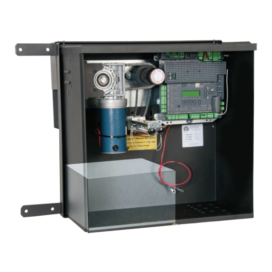
7251 / 7351 Slide Gate Operator INSTALLATION AND PROGRAMMING MANUAL 18.4 PART DRAWINGS 7251 POST MOUNT CHASSIS DIMENSIONS www.ApolloGateOpeners.com | (800) 878-7829 | Sales@ApolloGateOpeners.com... - Page 75 7251 / 7351 Slide Gate Operator INSTALLATION AND PROGRAMMING MANUAL 7251 POST MOUNT CHASSIS, PARTS, AND 1050 CONTROL BOARD Chain Cover Idler Sprocket 7251 control box Lid, Control Box 1050 Circuit Board Bearing, Flange Sprocket, Drive, #40 Chain, 13 Tooth...
- Page 76 7251 / 7351 Slide Gate Operator INSTALLATION AND PROGRAMMING MANUAL 7351 PAD MOUNT CHASSIS, PARTS, AND 1050 CONTROL BOARD www.ApolloGateOpeners.com | (800) 878-7829 | Sales@ApolloGateOpeners.com...
- Page 77 7251 / 7351 Slide Gate Operator INSTALLATION AND PROGRAMMING MANUAL 7351 PAD MOUNT CHASSIS, PARTS, AND 1050 CONTROL BOARD Cover, 7351 Board, Control, 1050 7351 Chassis This drawing is a representation and should be used for parts reference only. www.ApolloGateOpeners.com | (800) 878-7829 | Sales@ApolloGateOpeners.com...
- Page 78 7251 / 7351 Slide Gate Operator INSTALLATION AND PROGRAMMING MANUAL 7251/7351 BASIC PARTS BOM Part Name Part Number 7251/7351 Models Bearing, Flange UCFL202 Board, Control, 1050 1050US Chain Cover 10032590 7251 Cover, 7351 10030490 7351 Lid, Control Box 10053890 7251...
- Page 79 7251 / 7351 Slide Gate Operator INSTALLATION AND PROGRAMMING MANUAL (This page intentional blank) www.ApolloGateOpeners.com | (800) 878-7829 | Sales@ApolloGateOpeners.com...
-
Page 80: Warranty
This warranty will be interpreted, construed, and enforced in all respects in the name plate of a manufacturer other than HySecurity or Nice and they are not a accordance with the laws of the State of Washington, without reference to its part of the base model. - Page 81 7251 / 7351 Slide Gate Operator INSTALLATION AND PROGRAMMING MANUAL (This page intentional blank) www.ApolloGateOpeners.com | (800) 878-7829 | Sales@ApolloGateOpeners.com...
- Page 82 7251 / 7351 Slide Gate Operator INSTALLATION AND PROGRAMMING MANUAL DOCUMENT REVISIONS NAME DESCRIPTION OF CHANGE DATE Curtis Harvey Rev A: Released for publication. 11/12/2019 INSTALLATION INFORMATION AND SIGN-OFFS Installation Acceptance Address where opener is located Installer name, number and address End user name and telephone number www.ApolloGateOpeners.com | (800) 878-7829 | Sales@ApolloGateOpeners.com...
Need help?
Do you have a question about the 7251 and is the answer not in the manual?
Questions and answers