Table of Contents
Advertisement
Advertisement
Table of Contents

Subscribe to Our Youtube Channel
Related Manuals for Nice 936


Summary of Contents for Nice 936
- Page 1 Nice 936 Control Board Vehicular Gate Control Board...
- Page 2 This page intentionally left blank.
-
Page 3: Table Of Contents
Figure 7.1 - Open Limit Indicator Figure 7.2 - Close Limit Indicator 1- OVERVIEW 7.3 - Position learn condition 1.1 - 936 Control board 8 - PROGRAMMABLE SETTINGS 1.2 - Main control board specifics 8.1 - Primary programing operations 2 - GATE INFORMATION 8.2 - Secondary programing operations... -
Page 4: Cautions And Notes
CAUTIONS AND NOTES This instruction manual is intended to aid the installer in the overall process The 936 control board is housed in a protective plastic enclosure that includes of correct installation at the desired location. Periodically, the manual will two 7-segment LEDs, five dedicated programming buttons and three buttons... -
Page 5: Gate Latches
2.2 - Gate latches • Follow the recommended maintenance schedule of one inspection per every 180 days of use. In association with this gate controller and these operators, at no time should • Do not allow children to play in the area of the operator or to play with any manual gate latches or locks be used. -
Page 6: Gate System Safety Devices
One or more non-contact sensors must be used in any • Install a proper electrical ground to a gate operator and attach the situation or area where entrapment may have the possibility of ground rod to the earth ground connector on the 936 board (see section occurring. 5) . - Page 7 4.3.16 Protrusions shall not be permitted on any gate, refer to ASTM F2200 4.3.39 Safety sensors must be present at all times. The hard wired safety for exceptions, if any. sensors must be arranged and installed in such a manner so that the communication between gate operator and sensor(s) are never 4.3.17 Gates shall not be designed, constructed and installed in such a man- interrupted or severed by mechanical damage or movement.
-
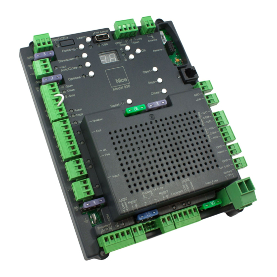
Page 8: Circuit Board
5 - CIRCUIT BOARD Figure 5.1 - Contol Board Overview Page 5 of 21... -
Page 9: Wiring
Power input connections should be wired as follows: Connect wires to the solar panel terminal block. The positive wire of the panel connects to the right terminal marked “+”. Note: The indicator light above the terminal block will illuminate red if connected with incorrect polarity. If solar power is to be used it will be necessary to program control board for STANDBY operation. - Page 10 Figure 6.3 - 816 Wiring Figure 6.4 - 416 Wiring Page 7 of 21...
-
Page 11: Set-Up
7.2 - Setting the limit switches reverse the orange and white limit wires. *Note - If a Nice brand remote will be used Once the "Limit 1 Close" light is seen in in the with this board, see Sec. 10 now fully intended closed position, proceed to for programming. -
Page 12: Programmable Settings
• On-board control station o Open - Hold to open o Close - Hold to close • Nice OXI/A radio receiver o Channel 1 - Hold to open o Channel 2 - Hold to close *Note - Motor direction must be verified and limits must be adjusted before initializing the learn procedure. -
Page 13: Secondary Programing Operations
8.2.1 - BlueBus Scan: THE BELOW STEPS ARE FOLLOWED FOR ALL OPTION Initiates an internal scan which clears any previous BlueBus devices in memory and adds TREE ITEMS EXCEPT FOR BLUEBUS SCAN any devices currently detected. 1. Press and release the Option button. 1. -
Page 14: Accessory Inputs And Outputs
8.2.4 - Radio Channel: Allows the user to determine Nice OXI/A transmitter channel operation. Setting Values: +24V 1 - Ch.1 = Step | Ch.2 = No Program (default) 2 - Ch.1 = No Program | Ch.2 = Step This terminal is an internally fused (0.3A) output for external 24 volt accessories. -
Page 15: Outputs
1. Have a functioning Nice 2-button or 4-button remote control with a battery installed prior to programming the remote control. Press and hold the button on the side of the Nice receiver until the led illumi- nates green on the Nice receiver, then release the button. -
Page 16: Display And Inspection
11.1 Status Display Outputs Table 11.1 11.2 Points for Routine Inspection Proper inspection of all equipment is required to ensure continuous functionality, safety and to ensure reliable operation in all weather conditions. Inspect electrical assemblies and wiring installations for damage, general condition, and proper functioning to ensure the continued satisfactory operation of the electrical system. -
Page 17: General Layout
12.1 Swing gate Entrapment Protection Inputs - Typical Installation Diagram Utilizing Loop Sensors and Photocells Loop (Safety) Outside Gate gate gate Loop (Shadow) Photo Photo Loop (Safety) Loop (Exit) Figure 12.1 - Layout for In-Ground Loops Entrapment Protection Inputs - Typical Installation Diagram Utilizing Photocells Outside Gate Photo 1... -
Page 18: Accessories And Sensors
- ACCESSORIES AND SENSORS 13.1 External Entrapment Protection: • Non-contact and contact sensors must be installed individually or in combination with each other to provide external entrapment protection. • Care should be exercised to reduce the risk of nuisance tripping, such as when a vehicle trips the sensor while the gate is still moving, and one or more non-contact sensors shall be located where the risk of entrapment or obstruction exists, such as the perimeter reachable by a moving gate or barrier. -
Page 19: Emergency Vehicle Access
- EMERGENCY VEHICLE ACCESS 15 - GLOSSARY COMMERCIAL / GENERAL ACCESS VEHICULAR GATE OPERATOR- CLASS II - ENTRAPMENT - GATE - 1 .3 INHERENT ENTRAPMENT SENSOR SYSTEM - INDUSTRIAL / LIMITED ACCESS VEHICULAR GATE OPERATOR- 1 .4 CLASS III - 1 .5 RESTRICTED ACCESS VEHICULAR GATE OPERATOR-CLASS IV - 1 .6... -
Page 20: Maintenance Schedule
Table 16.1 COMPLETE BASIC Alarm Active the primary (inherent) reverse system by blocking the gate with a solid object. The gate should reverse momentarily then stop. Restart the gate and block again with a solid object. The gate should reverse momentarily, then stop, and go into hard shutdown with an alarm. Batteries should be replaced at the lesser of either the battery manufacturer's recomeded time Battery period or when the battery is no longer capable of sustaining a charge. -
Page 21: Installation Checklist
18 - INSTALLATION CHECKLIST Left box is for installer check off and the right box is for cus- tomer check off. 1. The gate has been checked to make sure it is level and moves freely in both directions. 2. Potential pinch areas have been guarded so as to be inaccessible OR have contact and/or non-contact obstruction sensing devices installed. - Page 22 This page intentionally left blank.
- Page 23 This page intentionally left blank.
- Page 24 Contact us Nice Group USA Inc. 12625 Wetmore Road Suite 218 San Antonio, TX 78247 Ph. +1.210.545.2900 www.niceforyou.us r.15.09_7.0...
Need help?
Do you have a question about the 936 and is the answer not in the manual?
Questions and answers