Table of Contents
Advertisement
Control Box
120 Volt indoor
Transformer
(surge protector
not supplied)
Run 1000' (max.) of low
voltage wire to control
box from transformer
(wire not included).
12 Volt automotive or marine
type battery in weather proof
housing (not included).
This product meets the requirements of UL325,
the standard for gate operator safety.
MM271
Installation Manual
Gate Swings Evenly and Freely
Hung Firmly and Plumb
Single Gate Operator
Post Bracket
Power Cable
PVC conduit (not included)
to protect wire from lawn
mowers and weed eaters.
Example of finished installation
(Installations vary slightly for different types of gates)
Warning Sign
Horizontal Support
Gate Bracket
Closed Position Stop Plate
Fence Post Set in Concrete
Advertisement
Table of Contents

Subscribe to Our Youtube Channel
Related Manuals for Nice Mighty Mule MM271


Summary of Contents for Nice Mighty Mule MM271
- Page 1 MM271 Installation Manual Gate Swings Evenly and Freely Control Box Hung Firmly and Plumb Warning Sign Single Gate Operator Post Bracket Horizontal Support 120 Volt indoor Transformer (surge protector Gate Bracket not supplied) Closed Position Stop Plate Power Cable PVC conduit (not included) Fence Post Set in Concrete to protect wire from lawn Run 1000' (max.) of low...
- Page 2 WARNING DO NOT SPLICE ANY POWER WIRES! DO NOT MODIFY THE BATTERY HARNESS! THIS WILL VOID YOUR MANUFACTURER’S WARRANTY. Low voltage wire for transformer not included.
- Page 3 Failure to follow installation and safety instructions can result in hazards developing due to improper assembly. You agree to properly install this product and that if you fail to do so Nice North America LLC, shall in no event be liable for direct, indirect, incidental, special or consequential damages or loss of profits whether based in contract tort or any other legal theory during the course of the warranty or at any time thereafter.
-
Page 4: Table Of Contents
Table of Contents Please Read This First! ......................1 Before You Begin to Install Your Automatic Gate Opener .................. 1 Important Safety Information ....................2 Manually Opening and Closing Gate ....................... 2 For the Installer and End User......................... 3 Installing Warning Signs and Pedestrian Gates ....................7 Required Safety Precautions for Gates...................... -
Page 5: Please Read This First
Please Read This First! Thank you for purchasing a Mighty Mule Gate Operator— The Mighty Mule Gate Operator features Dual Sense Nice North America's "do-it-yourself" automatic gate Technology™. This feature makes the gate stop and operator! When correctly installed and properly used, your... -
Page 6: Important Safety Information
Important Safety Information Because automatic gate operators produce high levels be completely exhaustive in nature. It does, however, of force, consumers need to know the potential hazards provide an overview of the safe design, installation, and use associated with improperly designed, installed, and of this product. -
Page 7: For The Installer And End User
Important Safety Information For the Installer and End User WARNING To reduce the risk of injury or death: KEEP GATES PROPERLY MAINTAINED. Read the user’s READ AND FOLLOW ALL INSTRUCTIONS. manual. Have a qualified service person make repairs to gate Never let children operate or play with gate controls. - Page 8 Important Safety Information For the Installer and End User Typical Entrapment Zones are shown in the diagrams on page 3: Zone 1 – leading edge of the gate and the fence post. Zone 2 – between the gate and the gate post. Zone 3 –...
- Page 9 See page 28 for Mighty Mule web site (www.mightymule.com), by maintenance procedures. contacting Nice North America, at 5919 Sea Otter Place, Carlsbad, CA 92010 or by calling 1-800-543- 1236 and requesting a duplicate copy.
- Page 10 Important Safety Information For the Installer and End User Mighty Mule gate operators utilize Dual Sense Technology One or more edge sensors may be located at the leading ™ entrapment protection. Dual Sense Technology is built edge, bottom edge, and post edge, both inside and outside ™...
-
Page 11: Installing Warning Signs And Pedestrian Gates
We recommend using the Bulldog Pedestrian Gate Lock (Call the Nice North America Sales Department at 800-543-4283) for controlled access. -
Page 12: Required Safety Precautions For Gates
Important Safety Information Required Safety Precautions for Gates These warning labels should be found at the locations specified below. If any of them are missing, immediately contact Nice North America for replacements. WARNING AVERTISSEMENT Moving gate can cause injury or death! 1. -
Page 13: Technical Specifications
Technical Specifications Mighty Mule 271 Gate Opener DRIVE Low friction screw drive (linear actuator) rated for -5 °F to +160 °F (-20 °C to +71 °C). Powered by a 12 V motor with integral gear reducer. Motor speed reduced to 280 rpm. Maximum opening arc of 110°. -
Page 14: Before You Begin
Before You Begin Powering Options Determine Charging Option for Battery: Transformer OR Solar NEVER USE TRANSFORMER AND SOLAR PANEL(S) AT THE SAME TIME. It will damage the control board. IMPORTANT: ¾ The Mighty Mule gate operator is designed and intended for use with a 12 Volt automotive or marine type battery. The battery must be placed inside a weatherproof case and located within 6 feet from the Control Box. -
Page 15: Check Existing Gate Size And Material
Check Existing Gate Size and Material • Gate size: Up to 12 feet and up to 300 lbs • Type of gate material: Vinyl, aluminum, chain link, farm tube, wrought iron, wood. Not rated for use on solid surface gates. IMPORTANT: Check for Proper Gate Installation ¾... -
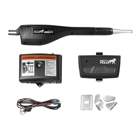
Page 16: Items Included
Items Included Warning Signs (2) Transformer Closed Position Operator Arm Stop Plate Control Box MMT103 Transmitter Gate Bracket Post Pivot Bracket Post Bracket 8” Nylon Cable Tie (6) 3/8” Washer (7) 5/16” Washer (1) 3/8” x 8” Bolt (2) 3/8” x 1-1/2” Bolt (1) Hairpin Clip (2) 5/16”... -
Page 17: Items Not Included
Items Not Included ¾ 12 Volt automotive or marine battery and a weather ¾ Depending on the type of gate, a horizontal proof case. cross member or mounting plate may be needed to mount the front of the operator and gate ¾... - Page 18 Gate Operator Installation Reinforcement and Gate Bracket Mounting Reinforcement and Gate Bracket Mounting Gate Gate Bracket Bracket Muf er Clamp (not supplied) Gate Gate Bracket Bracket Muf er Clamp (not supplied) Thin Walled Wood or Metal Tube Gate Reinforcement Thin Walled (not supplied) Wood or Metal Tube Gate...
- Page 19 Gate Operator Installation OPEN gate and reattach operator with clevis pin. Check to Secure post pivot bracket to post bracket with the hardware ensure the operator is level. provided (Q,K,U) when you have achieved the 1” clearance shown in Step 5 in both open and closed positions. 3 6 8 Remove clamps, post bracket, gate bracket, and operator.
-
Page 20: Closed Position Stop Plate Installation
Gate Operator Installation 6 12 Attach gate bracket assembly to gate cross support. Attach and secure operator assembly to brackets. Check for level. Adjust post bracket if necessary. Tighten all bolts and remove excess length on post and gate bracket bolts with hacksaw. Closed Position Stop Plate Installation Remove the arm from the front bracket then attach closed position stop Position gate stop with gate CLOSED to fence post. -
Page 21: Control Box & Battery Installation
Control Box & Battery Installation Locate control box mounting area. IMPORTANT: Be sure to mount Mount control box on piece of treated plywood then attach it to post or fence using screws. box at least 3 feet from AC power and 3 feet off the ground. Make sure control box is turned OFF. -
Page 22: Transformer Wiring Installation
Transformer Wiring Installation NOTE: If using a solar panel charging kit, go to page 19. WARNING Before digging contact local authorities to locate underground utilities such as electric and gas service. CL OS AU TO TI M ST AL FO RC 12 0 OF F M AX... -
Page 23: Solar Panel Installation
Solar Panel Installation CL OS AU TO TI M ST AL FO RC 12 0 OF F M AX C1 5 ED 1 M IN R2 0 IC 4 T U S S TA P O W LE D3 C H G C H G VA R1 C O M... -
Page 24: Transmitter Programming
Transmitter Programming Programming a MMT103 Transmitter. ON/OFF Switch Take hold of your transmitter. Turn off control box. Press and hold a preferred transmitter button while sliding the ON/OFF switch to the ON position. Continue to hold transmitter button for 8 - 10 seconds. You will hear a single or a series of beeps, followed by a pause then a single beep. - Page 25 Changes, modifications or adjustments not expressly Once you have your Mighty Mule transmitter programmed, approved by Nice North America LLC could void the user’s authority to consult your vehicle's HomeLink instructions section for operate this equipment. There Are No User Serviceable Parts.
-
Page 26: Setting Closed Limit Position
Setting Closed Limit Position C L O T IM S T A 1 2 0 C 1 5 E D 1 M IN R2 0 IC 4 T U S S T A P O W L E D C H G VA R1 C H G C O M... -
Page 27: Setting Dual Sense Detection & Auto Close Timer
Setting Dual Sense Detection & Auto Close Timer CL OS AU TO TI M ST AL FO RC With the Control Panel OFF, remove control panel cover by unscrewing 12 0 OF F M AX C1 5 ED 1 M IN R2 0 IC 4 center cover fastener. -
Page 28: Connecting Additional Devices
Connecting Additional Devices Mighty Mule strongly recommends the use of additional obstruction detection devices. However, we do not endorse any specific brand names. Only use products that are listed to be in compliance with any applicable UL safety standards and national and regional codes. -
Page 29: Control Board Connections
Control Board Connections NOTES: • All accessory inputs are dry-contact, normally open, inputs. DO NOT apply external voltage sources to these inputs. • All accessory inputs are connected with respect to COMMON terminal. CHGR: Power Input Terminals: • Input terminals for transformer. CHGR: Power Input Terminals: •... -
Page 30: Connecting Accessories
Connecting Accessories Automatic Gate Lock Edge Sensor Mighty Mule Photo Beams Push Button Control Blue Black Yellow Shield NOTE: Connections are for typical applications. For Mighty Mule additional connection options not illustrated here refer to Vehicle Sensor the accessory manual for details. Refer to Vehicle Sensor manual for additional information if needed. -
Page 31: Maintenance
¾ Replace batteries every 2-3 years and properly recycle old batteries. Troubleshooting Guide If your gate operator does not function properly after it is installed, use this guide before calling the Nice North America Service Department. Audible Feedback... -
Page 32: Visual Feedback
Use the 24/7 Troubleshooting "Wizard" located at www.mightymule.com. If you are unable to solve the problem, call the Nice North America Service Department at (800) 543-1236, or (850) 575-4144. Refer to the serial number (located on the back of opener arm) and date of purchase when calling for assistance. -
Page 33: Accessories
Accessories Accessories are Available From Your Retail Store Solar Panel (FM123) The Solar Panel is a 10 watt solar powered battery charger for use with the Mighty Mule 271 gate operator systems. Particularly suited for remote installations, each Solar Panel comes with tubular steel support, mounting clips, wire connectors, and 10 ft. - Page 34 The contents of all material available on this installation manual are copyrighted by Nice North America LLC (“Nice North America”), unless otherwise indicated. All rights are reserved by Nice North America, and content may not be reproduced, downloaded, disseminated, published, or transferred in any form or by any means, except with the prior, written permis- sion of Nice North America.
-
Page 35: Gate Operator Installation Checklist
Gate Operator Installation Checklist The gate has been checked to make sure it is level and moves freely in both directions. Potential pinch areas have been guarded so as to be inaccessible OR have sensing edges and/or photo beam obstruction ... - Page 36 Mighty Mule is a registered trademark of Nice North America LLC. All rights reserved. The contents of all material available on this installation manual are copyrighted by Nice North America LLC (“Nice North America”), unless otherwise indicated. All rights are reserved by Nice North America, and content may not be reproduced, downloaded, disseminated, published, or transferred in any form or by any means, except with the prior, written permission of Nice North America.
Need help?
Do you have a question about the Mighty Mule MM271 and is the answer not in the manual?
Questions and answers
Hello..... my gate operates with the PIN pad and the wight sensor, as well as with the remote.. however it has recently begun to open on its own... any advice as to to=rouble shoot the problem?