
Related Manuals for Nice ROX Series


Summary of Contents for Nice ROX Series
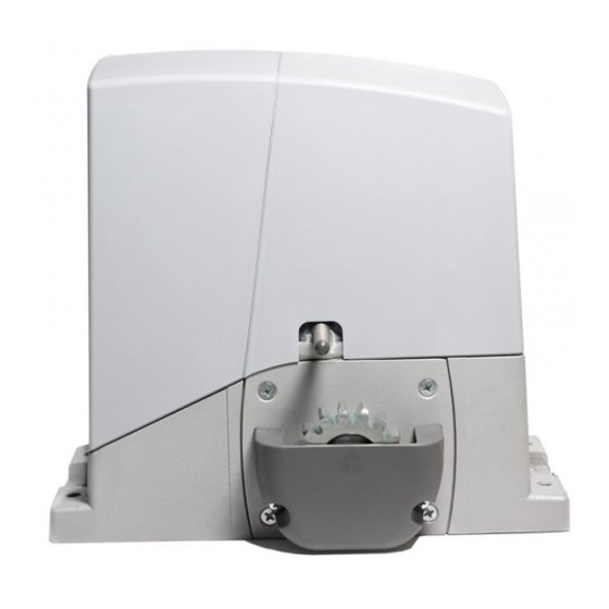
- Page 1 ROX600 ROX1000 ROX1000/V1 For sliding gates EN - Instructions and warnings for installation and use...
-
Page 3: Table Of Contents
CONTENTS GENERAL WARNINGS SAFETY - INSTALLATION - USE 1 - PRODUCT DESCRIPTION AND INTENDED USE 2 - OPERATING LIMITS 3 - INSTALLATION 4 - ELECTRICAL CONNECTIONS 4.1 - Types of electrical cables 4.2 - Electrical cable connections 5 - STARTING THE AUTOMATION AND CHECKING THE CONNECTIONS 5.1 - Hooking the automation up to the mains 6 - TESTING AND COMMISSIONING... -
Page 4: General Warnings Safety - Installation - Use
GENERAL WARNINGS SAFETY - INSTALLATION - USE (instructions translated from Italian) ATTENTION Important safety instructions. Follow all instructions as improper installation may cause serious damage ATTENTION Important safety instructions. It is important for you to comply with these instructions for your own and other people’s safety. -
Page 5: Product Description And Intended Use
4 ÷ 6 6 ÷ 8 8 ÷ 10 10 ÷ 12 Caution! Any other use or use with dimensions greater than specified is non-conforming. Nice declines all liability for damage and injury resulting for non-conforming use. English – 3... -
Page 6: Installation
Fig. 1 shows the contents of the package: check that everything is Fig. 2 shows the location of the components of a typical installation present and correct. using Nice accessories: a - ROX gearmotor b - photocells c - posts for photocells... - Page 7 Dig the foundation and route the electric cable ducting Secure the two anchors to the foundation plate with one 25 ÷ 35 mm nut above and one below. Tighten the lower nut in such a way that the thread protrudes by 25/35 mm. Now cast the concrete to secure the foundation plate.
- Page 8 d - screw down the adjuster screws so that the gearmotor is at the proper height, leaving a gap of 1-2 mm between the pinion and the rack (this is to prevent the gate loading the gearmotor shaft) e / f / g - release the gearmotor h - open the gate fully by hand 1÷2 mm i - rest the first section of rack on the gearmotor’s pinion:...
- Page 9 m - slide the gate by hand and, using the pinion as a ref- erence, install the other sections of rack 1÷2 mm n - cut any excess rack off the end Slide the gate open and closed by hand to check that the rack is properly aligned with the pinion. N.B.: make sure that there is a gap of 1-2 mm between the rack and pinion for the entire length of the gate 1÷2 mm Tighten the nuts securing the gearmotor to the foundation...
- Page 10 2-3 cm CLOSE: a - slide the gate closed by hand, stopping it 2/3 cm before the mechanical stop b - slide the limit switch bracket along the rack in the close direction until the limit switch trips (you will hear it click) c - after you hear the ‘click’, move the bracket further forwards by 2 cm (minimum) d - secure the bracket to the rack with the provided grub screws 2-3 cm...
-
Page 11: Electrical Connections
IN PARALLEL. • Contacts must be mechanical and disconnected from any voltage. Sensitive No specific input; use Nice equipment: edges - fixed sensitive edges: use the TCE interface - mobile sensitive edges: use the FT210 unit or IRW interface Refer to the product’s instruction manual for details... -
Page 12: Starting The Automation And Checking The Connections
AERIAL = AERIAL LIMIT SWITCH = LIMIT SWITCH PROGRAM = MICRO SWITCHES FLASH = FLASHER SWITCH BOOST = STARTCONDEN- LED RADIO = RADIO LED CAPACITOR SATOR LED PHOTO = PHOTOCELL LEDS = CAPACITOR RUN CAPACITOR LED P.P. = STEP-BY-STEP LED MOTOR = MOTOR LED OK... -
Page 13: Testing And Commissioning
Manually lock the gearmotor Power the automation up and check: - that the OK led is flashing regularly: 1 flash per second - that the gate does not move and that the flasher is off if any of these conditions are not satisfied, proceed as follows (step 05) Shut off mains power to the automation and check the electrical connections, photocell alignment, and fuses. -
Page 14: Commissioning
Using the key switch, control key or radio transmitter, test the opening and closing of the gate and make sure that it moves in the in- tended direction The test should be carried out a number of times to make sure that the gate moves smoothly, that there are no points of excessive friction and that there are no defects in the assembly or adjustments Check the operation of the safety equipment, one by one (photocells, sensitive edges, etc.) Check the operation of the photocells and any interference with other equipment:... -
Page 15: Control Unit: Programming Keys
↕ press and release the desired key on the radio release the RADIO key exactly when the led behaves transmitter to be memorized in the specified manner (on, flashing, off) hold down the desired key on the radio transmitter correct procedure to be memorized release the transmitter key INCORRECT procedure... -
Page 16: Programmable Functions
TP (Pause Time) Operating mode Adjustment sets the time between the end of select ‘Automatic’ and set micro switch 2 to ‘ON’ an Open movement and the start set trimmer TP to the desired value; of the next Close movement to check the time setting, run a full Open movements and see how long it takes before the Close movement starts. -
Page 17: Integrated Radio Receiver
Switch 5: This function, when set in Automatic mode, holds the gate open only for the time required for vehicles or pedestrians to pass through it; when the Photo device is cleared, the movement stops and a Close movement starts after a 5 second delay. If the functions is set in Semiautomatic mode, when the photocells are tripped while the gate is closing, automatic Close is activated with the programmed Pause Time. -
Page 18: Remote" Memorisation
• Mode 2: Table 9 freely assigns a command among those listed in table 9. For each phase, only one key is memorised (the one pressed during Transmitter key Command memorisation). Step-by-step (One memory location is occupied for each key). STOP Open Close... -
Page 19: Adding Or Removing Devices
STOP FURTHER DETAILS 8.1 - Adding or removing devices You can add or remove devices at any timee. STOP input Input that stops movement immediately, followed by a brief reverse of the manoeuvre. You may connect devices with NC contacts to this input; multiple devices can be connected in series. N.B.: when the NC contact opens, the automation stops and reverses its direction briefly. -
Page 20: Scrapping
Table 10 OK LED Cause Solution Malfunction Make sure there is power supply; check to see if the fuses are blown; if necessary, identify the reason for the failure and then replace them with others of the same type Serious There is a serious malfunction;... -
Page 21: Maintenance
TECHNICAL SPECIFICATIONS All technical specifications stated herein refer to an ambient temperature of 20° C (± 5° C). • Nice S.p.a. reserves the right to apply modifica- tions to products at any time when deemed necessary, maintaining the same intended use and functionality. -
Page 22: Ce Declaration Of Conformity
2004/108/EC (EMC); 2006/42/EC (MD) Annex II, part B Note: The contents of this declaration correspond to declarations in the official document filed in the offices of Nice S.p.a. and, in particu- lar, the latest version thereof available prior to the printing of this manual. The text herein has been re-edited for editorial purposes. A copy of the original declaration can be requested from Nice S.p.A. -
Page 23: User Manual (End User Version)
Arrange a periodic maintenance schedule with your installation technician. Nice recommends that maintenance checks be carried out every six months for normal domestic use, but this interval may very depending on the intensity of use. - Page 24 Nice SpA Oderzo TV Italia www.niceforyou.com info@niceforyou.com...
Need help?
Do you have a question about the ROX Series and is the answer not in the manual?
Questions and answers