Table of Contents
Advertisement
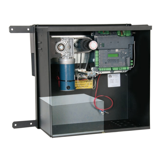
Nice Slide Gate
Operator
Vehicular Slide Gate Operator
Programming & controls, connections and safety
information for the 7251/7351 slide gate operator
7351 pad mount with 1050 control board
Revision 5.0.0.0_4-2019
Part #10001300
Model 7251/7351
1050 Control Board
7251 post mount with 1050 control board
Advertisement
Table of Contents

Subscribe to Our Youtube Channel
Related Manuals for Nice 7251


Summary of Contents for Nice 7251
- Page 1 Model 7251/7351 Vehicular Slide Gate Operator 1050 Control Board Programming & controls, connections and safety information for the 7251/7351 slide gate operator 7251 post mount with 1050 control board 7351 pad mount with 1050 control board Revision 5.0.0.0_4-2019 Part #10001300...
-
Page 3: Table Of Contents
6 - Entrapment Protection 20 - GENERAL LAYOUT AND SAFETY ACCESS 7 - Compatible External Sensors 21 - ACCESSORIES AND SENSORS 8 - 7251-7351 PARTS IDENTIFICATION 21.1 - Monitored Safety Device Types 9 - 7251 INSTALLATION 22 - IRB-RET WIRING DIAGRAM 9.1 - POST INSTALLATION... -
Page 4: Overview
The “Learn” function helps gate installer confi gure Nice 1050 This manual covers the following Nice operator control board semi-automatically for optimum models: 7251 and 7351. - Page 5 1.3 What is Included 1.4 Product Specifi cations Name 7251 - Post 7351 - Pad Model Mount Mount 7251/7351 Control Box Duty Cycle Varies based on charger type #10020715 Chain Bracket Drive Electromechanical #40 Roller Chain (35’) #72520001 Rate of Travel...
-
Page 6: General Safety Information
1.5 The installation of this product is not a “do- 2. General Safety Information it-yourself” project. A qualifi ed gate operator A gate operator is only a component in a gate installation company should be contacted system. The other parts of the gate system to install the gate operator to ensure a safe can include the gate, the external entrapment and reliable installation. - Page 7 Some operators are restricted in their usage application. All Nice USA operators are approved for use in all four UL325 Usage Classes. Appropriate Usage Classes are shown in the Specifi cations.
- Page 8 2.4 The operator is intended for installation only on gates used for vehicles. Pedestrians must 2.10 When utilizing a Nice board, a maximum be supplied with a separate access opening. of 8 entrapment protection devices may be The pedestrian access opening shall be connected.
-
Page 9: Use Of Vehicle Detectors
2.12 For a gate operator utilizing a contact 3. Use of Vehicle Detectors sensor (Edge): Use of vehicle detectors (loop detectors) is strongly a. One or more contact sensors shall be encouraged to prevent damage to vehicles located where the risk of entrapment or caused by gates closing on them. - Page 10 4.1.5 An existing gate latch shall be disabled 4.2.1.2 All openings shall be designed, when a manually operated gate is retrofitted. guarded, or screened from the bottom of the gate to the top of the gate or a 4.1.6 A gate latch shall not be installed on an minimum of 72 in.
-
Page 11: Maintenance Of Gate Systems
4.2.2 The following provisions shall apply to 4.3.5 Class IV vehicular horizontal swing Class IV vehicular horizontal slide gates: gates shall be designed, constructed and installed in accordance with security related 4.2.2.1 All weight bearing exposed rollers parameters specific to the application in 8 ft (2.44 m), or less, above grade shall be question. -
Page 12: Entrapment Protection
6. Entrapment Protection The UL325 standard for gate operators requires a minimum of two independent entrapment protection means for each entrapment zone. An entrapment zone is defi ned as follows: For slide gates, any locations between a moving gate and a counter opposing edge or surface where entrapment is possible up to a height of 6 ft. -
Page 13: Compatible External Sensors
Entrapment System (IES) (UL325 Type A) that Only the following external sensors have been monitors the force on the gate during travel. evaluated and tested with Nice gate systems and This system protects in both the open and are approved to be used for protection against... -
Page 14: 7251 Installation
9 - 7251 INSTALLATION 9.1 - POST INSTALLATION Install two 3” diameter posts parallel to the gate as shown. Posts must be secured in the ground as Centerline of gate necessary for your type of soil conditions and building Direction of opening codes. -
Page 15: Chain Bracket Mounting
9 - 7251 INSTALLATION 9.3 - CHAIN BRACKET MOUNTING Put the gate in the center of travel of the opening. The gate should remain in this position while the chain is attached to the operator. Mount chain brackets to gate frame either by using the four supplied 2”... -
Page 16: 7351 Parts Identification
10 - 7351 INSTALLATION 10.1 - CONCRETE PAD LOCATION Fabricate a concrete structure sufficient to stabilize 14” and mount the operator. Consult local building codes 3” to build a pad that meets or is sufficient for the soil 5” Area for conduit entry type and climate and capable of supporting the loads imposed by the operator during operation. -
Page 17: Chain Bracket Mounting
10 - 7351 INSTALLATION 10.3 - CHAIN BRACKET MOUNTING Put the gate in the center of travel. The gate should remain in this position while the chain is attached to the operator. Mount chain brackets to gate frame either by using the four supplied 2”... -
Page 18: Circuit Board Layout
Note: If supply is connected backwards a red LED will commercial operators. No connection is required on the illuminate below the terminal. If supply is connected properly a 7251/7351 system. green LED will illuminate. See 120VAC wiring section for more options. -
Page 19: Limit And Motor Wiring
13.1 - LIMIT AND MOTOR WIRING LEFT-HAND GATE - FACTORY DEFAULT RIGHT-HAND GATE 7251-7351 - LEFT-HAND GATE 7251-7351 - RIGHT-HAND GATE GREEN GREEN ORANGE WHITE WHITE: Close Limit 7251-7351 WHITE: Close Limit 7251-7351 ORANGE: Open Limit WHITE ORANGE: Open Limit... -
Page 20: Setting The Limit Switches
13.2 - SETTING THE LIMIT SWITCHES The limit adjustments are located inside the control box between the circuit board and motor assembly as shown. Increase travel for movement to the left Decrease Decrease travel for Limit adjustment travel for movement to assembly Limit adjustment movement to... -
Page 21: Quick Release Operation
13.3 - QUICK RELEASE OPERATION SOLAR MAIN DC POWER BATTERY POWER The quick release will allow for manual gate operation. Before disengaging the quick release make sure to disable power from the control board by unplugging the main and battery power terminals. -
Page 22: Learning Mode
14 - LEARNING MODE NICE has taken great care to simplify the installation, operation and safety of this device and to ensure longevity and reliability of the unit over time. The learning procedure consists of the following steps shown below:... -
Page 23: Accessory Inputs And Outputs
15 - ACCESSORY INPUTS AND OUTPUTS 15.1 - Outputs GATE OPERATOR ACCESSORY INPUTS: Auxiliary Inputs 1 (16), 2 (18): These digital inputs may be connected to the digital outputs of accessories and programmed to activate or control the gate operator in a number of different modes. Shorting the pins through a dry contact activates the programmed settings for these inputs. -
Page 24: Communication Buses
Plug-In Receiver with the affected Nice remote control. configuring the Master/Slave pair. 1. Press and hold the button on the side of the Nice receiver until the led on Perform the “Learn” process to configure open and close limits with the gate the Nice receiver illuminates green and keep the button pressed. -
Page 25: 120Vac Power Wiring
. This procedures need to be performed at the gate controller. hour minimum for solar charged systems) with connecting posts located on the 1. Press and hold the button on the side of the Nice receiver until the led on the top is recommended. -
Page 26: Optional Inputs
18 - OPTIONAL INPUTS 18.1 - Fire dept. connection 18.3 - Guard station 32 FIRE 34 OPEN 33 GND 35 STOP 36 CLOSE Dry contact input for a fire department control switch. Normally Open 37 GND (NO) contact must be shorted to ground through a switch to open the With the Guard Station switches installed, the user can operate the gate gate. -
Page 27: Radio Receiver Connection (Third Party)
18 - OPTIONAL INPUTS (CONT.) 19 - INSPECTION AND OPERATION 18.5 - Radio receiver connection (third party) Proper inspection of all equipment is required to ensure continuous functionality, safety and to ensure reliable operation in all weather conditions. 38 12V Inspect electrical assemblies and wiring installations for damage, general 39 OPEN condition, and proper functioning to ensure the continued satisfactory... -
Page 28: General Layout And Safety Access
20 - GENERAL LAYOUT AND SAFETY ACCESS Vehicular Protection Inputs - Typical Installation Diagram Utilizing Loop Sensors and Photocells Loop (Safety) Outside Gate 4’ Min. from closed gate 4’ Min. from closed gate Photo 2 Loop (Safety) Loop (Exit) Figure - LAYOUT FOR IN-GROUND LOOPS Entrapment Protection Inputs - Typical Installation Diagram Utilizing Photocells Other Entrapment zones may exist and must be protected. -
Page 29: Accessories And Sensors
21 - ACCESSORIES AND SENSORS EXTERNAL ENTRAPMENT PROTECTION Non-contact and contact sensors must be installed individually or in combination with each other to provide external entrapment protection. Care should be exercised to reduce the risk of nuisance tripping, such as when a vehicle trips the sensor while the gate is still moving, and one or more non- contact sensors shall be located where the risk of entrapment or obstruction exists, such as the perimeter reachable by a moving gate or barrier. -
Page 30: Monitored Safety Device Types
21 - ACCESSORIES AND SENSORS (CONT.) 21.1 - MONITORED SAFETY DEVICE TYPES BlueBus photo-eyes: The EPMOB photocell is a thru-beam device - consisting of a transmitter (TX) and a receiver (RX) that connects via two (2) wires. Polarity of the wiring is not important. EPMOBs may be wired in parallel to one another or directly to the board - it is not necessary to make a “home run”... -
Page 31: Irb-Ret Wiring Diagram
22 - IRB-RET Wiring Diagram 2 FREQUENCY Switch #1 - ON Switch #2,3,4 - OFF IRB-RET 1. Press “Functions” 2. Select #3 “Auxiliary IO” and Press “OK” 3. Select “In Aux 1” (or “In Aux 2”) and Press “OK”. 4. Select Open Pule or Close Pulse and “Press OK” 5. -
Page 32: Gem-103 Wiring Diagram
23 - GEM-103 Wiring Diagram TO 10K OHM RESISTANCE EDGE SENSOR Black & White Wires GEM-103 24 - WEL-200 Wiring Diagram EMX WEL-200 Wireless Edge Receiver Dip Switch Settings determine which relay activates when the associated edge is tripped. See WEL-200 manual for instructions for programming receiver/transmitter pairs. -
Page 33: Board Nomenclature
25 - BOARD NOMENCLATURE Incoming 30 LCD screen Amp fuse Spare fuses Open the gate Stop gate movement Reset Hard Shut down button Close the gate Selection up OK or Enter Selection down Force select Speed select Delay select Function select Display select Figure - GENERAL BOARD OVERVIEW THE PROGRAMMING BUTTONS INDICATED IN THE ABOVE REFERENCE SHOULD BE USED ONLY AFTER UNDERSTANDING THE... -
Page 34: Programming Buttons
(20% being the lowest setting). It is recommended to raise all of the speed • HOLD TO CLOSE Input must be maintain active for Closing settings to 100 for 7251/7351 slide gate operators. • FIRE Reset Hard Shut Down and Open the Gate •... -
Page 35: Display
26 - PROGRAMMING BUTTONS (CONT.) Events: Up to 8 weekly events (EV1 through EV8) can be programmed and • Set Anti-tailgate (Closes gate immediately after vehicle has cleared safety stored. Each event can be programmed to trigger at a specific time and sensors) can be assigned to any combination of days of the week (Monday through •... -
Page 36: Emergency Vehicle Access
27 - EMERGENCY VEHICLE ACCESS 28 - GLOSSARY 27.1 The automatic vehicular gate system must be designed to allow LOCK- Ceases all operator function except HIGH PRIORITY inputs. access to emergency vehicles under different operating conditions. COMMERCIAL / GENERAL ACCESS VEHICULAR GATE OPERATOR- 27.2 During normal powered operation, emergency vehicles access the CLASS II - A vehicular gate operator (or system) intended for use in a gate by use of the emergency vehicle access device installed on your... -
Page 37: Maintenance Schedule
29 - MAINTENANCE SCHEDULE Table 2 COMPLETE BASIC Alarm Activate the (inherent) reverse system by blocking the gate with a solid object. The gate should reverse momentarily then stop. Restart the gate and block again with a solid object. The gate should reverse momentarily, then stop, and go into hard shutdown with an alarm Backup System If operator is equipped with DC backup system, check to be sure the system opens the gate... - Page 38 30 - TROUBLESHOOTING (CONT.) Table 4: 1050 Board Display Read Out and Troubleshooting DISPLAY REASON POSSIBLE SOLUTION Dynamic M1 Actuator connected to Motor Check for obstruction in gate path or degraded gate hardware. 1 has a brief current spike and tripped Type A sensor.
-
Page 43: Warranty
This warranty will be interpreted, construed, and enforced in all respects in accordance name plate of a manufacturer other than HySecurity or Nice and they are not a part of with the laws of the State of Washington, without reference to its choice of law the base model. -
Page 44: Installation Checklist
33 - INSTALLATION CHECKLIST Left box is for installer check off and the right box is for customer check off. 1. The gate has been checked to make sure it is level and moves freely in both directions. 2. Potential pinch areas have been guarded so as to be inaccessible OR have contact and/or non-contact obstruction sensing devices installed. -
Page 45: Appendix - French Translations
34 - Appendix - French Translations... - Page 46 34 - Appendix - French Translations (Cont.)
- Page 47 34 - Appendix - French Translations (Cont.)
- Page 48 34 - Appendix - French Translations (Cont.)
- Page 52 Contact us Nice 6705 S. 209th St., Suite 101 Kent, WA 98032-2327 Ph. +1.253.867.3700 Fax +1.253.867.3702 www.hysecurity.com www.facebook.com/hsgateoperators...
Need help?
Do you have a question about the 7251 and is the answer not in the manual?
Questions and answers