Table of Contents
Advertisement
Quick Links
Advertisement
Table of Contents
Troubleshooting

Related Manuals for FCI MT100


Summary of Contents for FCI MT100
- Page 1 06EN003460 Rev. C...
- Page 2 (and does not include manufacture or processing uses). Any other use is strictly prohibited without the prior written consent of FCI. © Copyright 2019 by Fluid Components International LLC. All rights reserved. FCI is a registered trademark of Fluid Components International LLC. Information subject to change without notice.
-
Page 3: Table Of Contents
MT100 Multipoint Flow Meter 06EN003460 Rev. C Table of Contents Table of Contents......................................iii List of Figures ......................................List of Tables......................................vii GENERAL ......................................1 Description ......................................1 Theory of Operation ..................................1 Safety Instructions.....................................1 Order Verification ....................................2 Equipment Nameplate..................................2 Specifications ....................................3 INSTALLATION....................................5 Receiving/Inspection ..................................5 Pre-Installation Procedure.................................5... - Page 4 06EN003460 Rev. C MT100 Multipoint Flow Meter TROUBLESHOOTING ..................................87 Troubleshooting Equipment ................................87 Non-Maintenance Observations..............................87 General Function Check .................................89 Troubleshooting the Flow Element..............................91 Verification of the Electronics................................92 Safety Instructions...................................93 Delta R Check ....................................93 Heater Current Check ..................................94 Allowable Limits ....................................94 Defective Parts....................................95...
-
Page 5: List Of Figures
Figure 30 – MT100 Normal Process Display Screen..........................33 Figure 31 – microSD Card Socket J7 Location............................34 Figure 32 – SD Card Data Logging Example Screen (MT100 Configuration Software) .................35 Figure 33 – Chart: Flow Output Over Time with Various Flow Damping Values ..................36 Figure 34 –... - Page 6 06EN003460 Rev. C MT100 Multipoint Flow Meter Figure 40 – Connections for External MT100 Flow Input (EFI).......................73 Figure 41 – MT100 Configuration Software Output Tab with Modbus Selected..................74 Figure 42 – MT100 Configuration Software Modbus Tab, Serial Interface Configuration...............75 Figure 43 – ModScan32, Data Definition ..............................77...
- Page 7 Table 7 – HART Universal Commands..............................47 Table 8 – HART Common Practice Commands .............................55 Table 9 – MT100 HART Device Specific Command Groupings ......................58 Table 10 – HART Device Specific Commands ............................58 Table 11 – Command Status Bytes, Bit Assignments ..........................69...
- Page 8 06EN003460 Rev. C MT100 Multipoint Flow Meter This Page Intentionally Left Blank viii Fluid Components International LLC...
-
Page 9: General
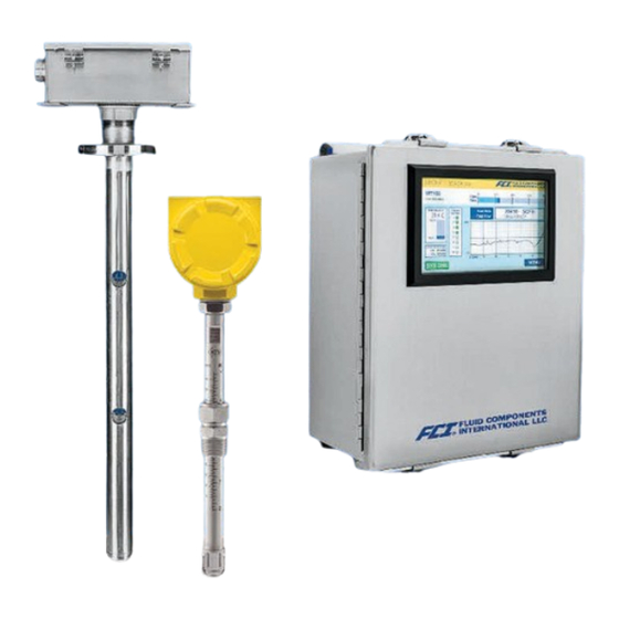
Description The MT100 is a thermal dispersion, industrial process grade air and gas multipoint insertion mass flow meter in a local probe/remote transmitter configuration. The instrument provides direct mass flow measuring and measures flow rate, totalized flow and temperature. An average of the individual flow signals (up to eight) gives an output signal that represents the total mass flow. -
Page 10: Order Verification
MT100S – Single point insertion element with flow and temperature process output MT100M – Multipoint element with flow and temperature process output Documentation and Accessories 06EN003460 MT100 Installation, Operation, & Maintenance Manual (this manual) 06EN003461 MT100 Configuration Software Manual Calibration Certification Documentation... -
Page 11: Specifications
MT100 Multipoint Flow Meter GENERAL ■ Agency Approvals (Optional) Specifications CE marking, CRN (pending, MT100S only) Instrument FM/FMc: Class I, Division 2, Groups A, B, C, and D ■ Measuring Capability Class II/III, Division 2, Groups E, F, and G... - Page 12 ■ Element Coatings and Materials Complies with 40 CFR 60 and 40 CFR 75; provides 24-hour interval For service in highly corrosive gases or erosive particulates, FCI automated test of low, mid and high span points, and interference can provide special coatings and wetted materials to protect, sensor check;...
-
Page 13: Installation
Verify the Delta R data sheet and the instrument information sheet are included in the instrument’s documentation package. If the above items are satisfactory then proceed with installation. If not, then stop and contact the FCI customer service representative for instructions. -
Page 14: Figure 1 - Mt100M: Multipoint Flow Element Showing Flat Area, Duct Mount (Side Mounted Horizontal Configuration Shown)
INSTALLATION MT100 Multipoint Flow Meter The above precautions are minimum requirements to be used. The complete use of ESD precautions can be found in the U.S. Department of Defense Handbook 263. Verify Serial Numbers Verify that the equipment tags on the remote enclosure and associated flow transmitter have matching serial numbers. -
Page 15: Figure 2 - Mt100M: Multipoint Flow Element Showing Flat Area, Flange Mount
MT100 Multipoint Flow Meter INSTALLATION C01289-1-1 Figure 2 – MT100M: Multipoint Flow Element Showing Flat Area, Flange Mount Reference Flat Markings CUSTOMER Reference Flat FLANGE CONNECTION 2-INCH 150 LB RF FLANGE, 316L SST PER ANSI/ASME B16.5 HORIZONTAL VERTICAL FLOW FLOW... -
Page 16: Install Flow Element
INSTALLATION MT100 Multipoint Flow Meter Install Flow Element Duct Flange Installation (MT100M) Install the duct mount flow element assembly as appropriate to its configuration. Refer to APPENDIX A, page for configuration information specific to the unit’s serial/tag number. Follow these steps to install the flow element. -
Page 17: Figure 4 - Duct Flange Mounting, Dimensions, And Mounting Hardware
MT100 Multipoint Flow Meter INSTALLATION SUGGESTED MOUNTING HOLE DIMENSIONS REFERENCE (ORIEN TATION) FLAT HERE FOR HORIZON TAL FLOW DIRECTION (CUSTOMER DUCT) Ø 6-BOLT TORQUE SEQUENCE 6X Ø .350 [9] THRU*, EQUALLY SPACED ON A Ø 7.00 [178] BOLT CIRCLE Ø 5.25 [133] THRU* MAX. -
Page 18: Figure 5 - Duct Flange Mounting, End Support Hardware (Optional)
INSTALLATION MT100 Multipoint Flow Meter SUGGESTED MOUNTING HOLE DIMENSIONS REFERENCE (ORIEN TATION) FLAT HERE FOR HORIZON TAL FLOW DIRECTION (CUSTOMER DUCT) Ø 6-BOLT TORQUE SEQUENCE 6X Ø .350 [9] THRU*, EQUALLY SPACED ON A Ø 7.00 [178] BOLT CIRCLE Ø 5.25 [133] THRU* MAX. -
Page 19: Figure 6 - Alternative Duct Flange Mounting, Dimensions And Mounting Hardware
MT100 Multipoint Flow Meter INSTALLATION Figure 6 – Alternative Duct Flange Mounting, Dimensions and Mounting Hardware Fluid Components International LLC... -
Page 20: Figure 7 - Alternative Duct Flange Mounting, End Support Hardware (Optional)
INSTALLATION MT100 Multipoint Flow Meter Figure 7 – Alternative Duct Flange Mounting, End Support Hardware (Optional) Fluid Components International LLC... -
Page 21: Figure 8 - Single Point, Fixed Rf Flange Process Connection
MT100 Multipoint Flow Meter INSTALLATION RF Flange Installation (MT100S, MT100M) The flange mount flow element is shown in Figure 8 and Figure 9 below. Attach the process mating flange with care. The correct orientation of the flow element must be maintained to ensure the calibrated accuracy. -
Page 22: Figure 9 - Multipoint, Rf Flange Process Connection (High Temp Shown)
INSTALLATION MT100 Multipoint Flow Meter Figure 9 – Multipoint, RF Flange Process Connection (High Temp Shown) Fluid Components International LLC... -
Page 23: Figure 10 - Multipoint Flanged Sensor Probe Example Installation
MT100 Multipoint Flow Meter INSTALLATION JUNCTION BOX; NEMA 4X ELECTRONICS ENCLOSURE, NEMA 4X, STAINLESS STEEL POWER CABLE (AC OR DC) SIGNAL OUTPUT CABLE (ANALOG OR DIGITAL) Figure 10 – Multipoint Flanged Sensor Probe Example Installation Ø 2 150# RFSS 3 LOCATING SCREWS 120° APART Figure 11 –... -
Page 24: Figure 12 -Single Point, Fixed 1" Welded Npt Process Connection
INSTALLATION MT100 Multipoint Flow Meter NPT Installation (MT100S, MT100M) Single and multipoint NPT pipe thread sensor assemblies are shown in Figure 12 and Figure 13 below. Apply sealant compatible with the process media to male threads. Carefully insert process mounting coupling. Tighten the flow element until snug and continue until flat and flow direction arrow are aligned with process flow. -
Page 25: Figure 14 - Compression Fitting Mounting Dimensions
MT100 Multipoint Flow Meter INSTALLATION Compression Fitting Installation (MT100S) A compression fitting flow element sensor is used for multi-single point insertion applications. The adjustable length of the compression fitting allows for precise sensor placement inside the pipe. The flow element is properly mounted when the center of the sensor head divides the pipe into equal areas as shown in Figure 14 below. -
Page 26: Figure 15 - Compression Fitting Process Connection (Optional Flange Shown)
INSTALLATION MT100 Multipoint Flow Meter Ø Figure 15 – Compression Fitting Process Connection (Optional Flange Shown) Fluid Components International LLC... -
Page 27: Figure 16 - Low Pressure Retractable Packing Gland, Npt Process Connection Shown
MT100 Multipoint Flow Meter INSTALLATION Adjustable/Retractable Packing Gland Installation (MT100S) Refer to drawings located in Appendix A for additional detail on packing gland probe installation. NPT and flange mounted gland are available. Isolation valves are typically used in packing gland applications. -
Page 28: Figure 17 - Medium Pressure Retractable Packing Gland, Flange Process Connection Shown
INSTALLATION MT100 Multipoint Flow Meter LOCKING COLLAR Ø 1 Figure 17 – Medium Pressure Retractable Packing Gland, Flange Process Connection Shown Fluid Components International LLC... -
Page 29: Figure 18 - Multiple Single Point Probe Installation (Packing Gland Shown)
14.6% of the pipe/stack inside diameter. Figure 18 below shows this and other key measurements for multi-probe installation. Note that FCI’s AVAL program that is run at order time provides the required measurements as a result of customer-entered parameters that define the instrument’s application. -
Page 30: Install Flow Transmitter
A silicone encapsulant/potting compound may be used to provide the isolation. Note: FCI recommends installing an AC power disconnect switch and fuse near the flow transmitter to interrupt power during installation, maintenance, calibration, and troubleshooting procedures. -
Page 31: Wiring
MT100 Multipoint Flow Meter INSTALLATION Wiring Table 2 below shows the smallest copper wire (maximum AWG number) that can be used for the listed cabling. Contact FCI concerning greater distances than those listed in the chart. Refer to APPENDIX A, page for specific wiring/cabling information. -
Page 32: Figure 21 - Mt100 Electronics Enclosure Label
Electronics Enclosure Label Affixed to the inside enclosure door below the display window is a label that identifies various connectors and features on the MT100 main board and optional extension (upper) board, as well as the visible part of the power supply board. See Figure 21 below. Use this label as a guide to locating the SD card socket, the battery holder, input power fuse, and connectors (shown with function and terminal assignments). -
Page 33: Figure 22 - Flow Element Connections
(no connection to the flow element enclosure). As shown in Figure 22 below the MT100 flow element sensors connect to detachable 9-position connector plugs (8 total) on the SB4 main board and the optional SB8 extension board (on standoffs). The connector plug accepts 28-16 AWG (0.14 mm -1.5 mm... -
Page 34: Figure 23 - Input Power And I/O Connections
INSTALLATION MT100 Multipoint Flow Meter Input Power Warning: Install an AC line disconnect switch with fuse or breaker between the power source and the flow meter. Always disconnect power before performing maintenance on wiring. As shown in Figure 23 below connect input power to the remote transmitter’s 3-position Phoenix connector P1 on the power supply board. -
Page 35: Figure 24 - Single Connection And Multidrop Hart Setups
MT100 Multipoint Flow Meter INSTALLATION I/O Connections As shown in Figure 23 the SB4 main board provides an input/output signal interface for connection to various peripheral interfaces. For these interfaces, route the cable/wires through a conduit opening at the enclosure bottom and connect to the appropriate connector/terminals. -
Page 36: Figure 25 - Modbus Wiring
INSTALLATION MT100 Multipoint Flow Meter 4-20 mA Output The MT100 is provided with two 4-20 mA current loop channels via the J9 Phoenix connector terminals. The connector accepts 28-16 AWG (0.14 mm -1.5 mm ) wire (refer to Table 2, page for wire size vs. -
Page 37: Figure 26 - Fieldbus/Profibus Wiring
(star fashion). For Fieldbus, a terminator (1 µF capacitor and 100 Ω resistor in series) is used on farthest ends of the trunk (i.e., at each end of the segment cable). For details on PROFIBUS operation refer to the MT100 PROFIBUS PA manual 06EN003474. -
Page 38: Figure 27 - Sink Output
INSTALLATION MT100 Multipoint Flow Meter Source/Sink Outputs Wire the source/sink outputs via the J8 Phoenix connector terminals as required for your device (using sink and/or source output as appropriate) as shown in Figure 27 Figure 28 below. The connector accepts 28-16 AWG (0.14 mm -1.5 mm... - Page 39 Modes, page (OPERATION section) for extended operation mode details. Service Port Connection, USB & Ethernet Listed below are the MT100 service ports, which are used to configure/monitor the instrument via a PC. See also Configuring the MT100, page 34. ● USB 2.0 – USB Type B connector J22: Use the USB port for local host PC connection to the instrument.
-
Page 40: Cabling Entry
INSTALLATION MT100 Multipoint Flow Meter Cabling Entry Cable entries for flow element and remote electronics enclosures are made via cable glands. Refer to APPENDIX A for specific information. Cable Gland A cable gland provides cable strain relief as well as a barrier against moisture. Follow the instructions below for cable gland installation. -
Page 41: Operation
Startup and Commissioning Verify the wiring and then apply power to the flow meter. As the instrument boots the LCD shows the FCI logo with a progress bar below it that fills up from left to right. After the progress bar completes (about 30 seconds) a screen similar to that shown in Figure 30 below is displayed. -
Page 42: Data Logging
The MT100 can record process data on a microSD memory card. Removing/Inserting Memory Card Refer to Figure 31 below. The MT100 comes with an 8 MB microSD card. Use a microSD card of up to 32 GB capacity, Class 2 or higher. 1. Tap MENU on the front panel display. -
Page 43: Figure 32 - Sd Card Data Logging Example Screen (Mt100 Configuration Software)
Programming Data Logging After installing the microSD card in the system use the MT100 Configuration Software application to configure and start/stop data logging. An example SD Card Logging tab screen is shown in Figure 32 below. Using this screen, which is part of the Basic Setup menu, specify the start date and time for logging (or check Start Now to start logging once programming is finished), the sample period for data gathering, and the duration in days/hours/minutes over which logging is to occur. -
Page 44: Flow Damping
Use the configurator software to adjust the flow damping setting (Advanced Setup/User Parameters) as required for your application. Refer to the MT100 Configuration Software manual 06EN003461 for details. As shown in Figure 33 below, an increase in flow damping value results in an output that is increasingly resistant to change (amplitude variations). -
Page 45: Cems Operation (Option)
(interference) and CAL (calibration) respectively (see Figure 34 above). If, however, an issue is detected in the FE and/or calibration FAIL (in red) is shown for INTF and/or CAL respectively. ● Automatic/Scheduled System Check – System checks are done automatically at a user-specified time. This is set up using the MT100 Configuration Software application only. - Page 46 Test Status field includes relay ON/OFF status. Observe also that the front panel SYS CHK button turns yellow and the Process Status Summary shows “CEMS In Progress” in red upon start of test. Refer to the MT100 Configuration Software manual 06EN003461 for details.
-
Page 47: Touch Screen Calibration
FEs. When less than 50% of the enabled FEs are functioning, the MT100 system outputs zeros for flow and temperature. 50% Rule Disabled: The MT100 system outputs the averaged values of any working FE in the system, even if it is down to one functional FE. Fluid Components International LLC... - Page 48 OPERATION MT100 Multipoint Flow Meter Turning ON or OFF a Specific Flow Element A specific flow element can be turned ON (online) or OFF (offline) as needed via the front panel HMI display. Tap MENU on the front panel HMI display. This brings up a list of items under the heading Service.
-
Page 49: Using Digital Outputs
OUNDATION a time. When a particular digital output is specified at order time the unit is configured appropriately at the factory. Use the MT100 configuration software (Configuration/Output) to change the digital output selection. Refer to the MT100 Configuration Software manual 06EN003461 for details. -
Page 50: Explanation Of Non-Zero Based And Zero Based Calibration
OPERATION MT100 Multipoint Flow Meter Explanation of Non-Zero Based and Zero Based Calibration Non-Zero Based Calibration In a non-zero based calibration, the low-limit output signal (4 mA) is equal to the minimum calibrated flow. The minimum calibrated flow is a value greater than zero. -
Page 51: Hart Operation
The primary function of the instrument’s HART interface is to present process data via process data commands 1, 3 and 9. The MT100 does not implement the HART Burst mode. A HART master that supports HART 7.0 and higher is required. If using a HART communicator, a unit that supports HART 7.0 or higher is required (i.e. -
Page 52: Figure 37 - Field Communicator Easy Upgrade Utility, Import Dd
EDDL Files The MT100 Series EDDL (Electronic Device Description Language) files are support files that provide an extended description of each object in the Virtual Field Device (VFD), and provide information needed for a control system or host to understand the meaning of the data in the VFD including the human interface. - Page 53 Shown below is service information as seen through the Emerson 475 HART communicator with FCI’ s DD files loaded. The same information seen by the 475 is shown in the DCS (Distributed Control System) when the MT100 Series HART DD files are loaded.
- Page 54 The configuration function eases the setup of the individual 4 20 mA current output channels. MT100 Series Calibration Limits (Example) The MT100 Series Calibration Limits function lets you review the limits that have been set for the Flow and Temperature process parameters.
-
Page 55: Hart Command List Reference
MT100 HART Universal Commands The MT100 HART supports Universal Commands 0 through 22 and 38 and 48. Commands 4 and 5 are reserved under Universal Command Specification Rev. 7.1 (HCF_SPEC-127, Revision 7.1) and not implemented in this specification. There is no HART command Table 7 below summarizes the instrument’s HART Universal command set and the data associated with each command. - Page 56 OPERATION MT100 Multipoint Flow Meter Command 1: Read Primary Variable (Flow Units, & Flow Value) Byte Format Description Request Data Bytes None Response Data Bytes Enum Primary Variable Units Code 1–4 Float Primary Variable Value Code Class Description Response Codes...
- Page 57 MT100 Multipoint Flow Meter OPERATION Command 7: Read Loop Configuration Byte Format Description Request Data Bytes None Response Data Bytes Unsigned-8 Polling Address of Device Enum Loop Current Mode Code Class Description Response Codes Success No Command-Specific Errors 1–127 Undefined...
- Page 58 OPERATION MT100 Multipoint Flow Meter Command 9: Read Device Variables with Status (Continued) Response Data Bytes Unsigned-8 Slot 4: Device Variable Code (continued) Enum Slot 4: Device Variable Classification Enum Slot 4: Units Code 36–39 Float Slot 4: Device Variable Value...
- Page 59 MT100 Multipoint Flow Meter OPERATION Command 12: Read Message Contained Within Device Byte Format Description Request Data Bytes None Response Data Bytes 0–11 Bitstring Device ID No. Code Class Description Response Codes Success No Command-Specific Errors 1–127 Undefined Command 13: Read Tag, Descriptor, Date...
- Page 60 OPERATION MT100 Multipoint Flow Meter Command 16: Read Final Assembly Number Byte Format Description Request Data Bytes None Response Data Bytes 0–2 Unsigned-24 STAK ELECT ASSY # Code Class Description Response Codes Success No Command-Specific Errors 1–127 Undefined Command 17: Write Message Into Device...
- Page 61 MT100 Multipoint Flow Meter OPERATION Command 21: Read Unique Identifier Associated with Long Tag Byte Format Description Request Data Bytes 0–31 Latin-1 Long Tag Response Data Bytes Unsigned-8 1–2 Enum Expanded Device Type Unsigned-8 Minimum Number Of Preambles From Master to Slave...
- Page 62 OPERATION MT100 Multipoint Flow Meter Command 48: Read Additional Device Status Byte Format Description Request Data Bytes 0–5 Bits Device-Specific Status (only first 6 bytes used, see page additional info) Bits Extended Device Status. Normally “0”; set to “1” (0x01) if maintenance is required.
-
Page 63: Table 8 - Hart Common Practice Commands
MT100 Multipoint Flow Meter OPERATION MT100 HART Common Practice Commands The MT100 supports Common Practice commands 35, 40, 42, 44, 45, 46, 50 and 51. Table 8 below summarizes the instrument’s HART Common Practice command set and the data associated with each command. - Page 64 OPERATION MT100 Multipoint Flow Meter Command 44: Write Primary Variable Units Byte Format Description Request Data Bytes Enum PV Units Code Response Data Bytes Enum PV Units Code Code Class Description Response Codes Success No Command-Specific Errors Undefined Error Invalid Selection 3–127...
- Page 65 MT100 Multipoint Flow Meter OPERATION Command 50: Read Dynamic Variable Assignments Byte Format Description Request Data Bytes None Response Data Bytes Unsigned-8 Device Variable assigned to the primary variable. Unsigned-8 Device Variable assigned to the secondary variable. Unsigned-8 Device Variable assigned to the tertiary variable.
-
Page 66: Table 9 - Mt100 Hart Device Specific Command Groupings
MT100 HART Device Specific Commands The MT100 Manufacturer Specific or Device Specific commands start at command 137. Use the device specific commands to setup and configure the MT100 Series instrument via HART. The MT100 device specific commands are grouped in functional categories as summarized in Table 9 below. - Page 67 MT100 Multipoint Flow Meter OPERATION Command 139: Write Totalizer State Byte Format Description Request Data Bytes Unsigned-8 Totalizer State: 0 = OFF; 1 = ON Response Data Bytes Unsigned-8 Totalizer State: 0 = OFF; 1 = ON Code Class Description...
- Page 68 OPERATION MT100 Multipoint Flow Meter Command 146: Write Customer Engineering Units Byte Format Description Request Data Bytes Unsigned-8 Units Code for Flow Unsigned-8 Units Code for Temperature Unsigned-8 Units Code for Totalizer Unsigned-8 Units Code for Pressure Response Data Bytes...
- Page 69 MT100 Multipoint Flow Meter OPERATION Command 150: Write “Write Protect Mode” Byte Format Description Request Data Bytes Unsigned-8 Write Protect Mode: 0x00 = Disable; 0x01 = Enable Response Data Bytes Unsigned-8 Write Protect Mode: 0x00 = Disable; 0x01 = Enable...
- Page 70 OPERATION MT100 Multipoint Flow Meter Command 159: Write Factory Restore Byte Format Description Request Data Bytes Unsigned-8 0x00 for Factory Restore Response Data Bytes Unsigned-8 0x00 for Factory Restore Code Class Description Response Codes Success No Command-Specific Errors 1–5 Undefined Misc.
- Page 71 MT100 Multipoint Flow Meter OPERATION Command 163: Write (4-20 mA) Output Channel #2 Parameters Byte Format Description Request Data Bytes 0–1 Unsigned-16 D/A Setting for 4 mA Out (OUTZ2) 2–3 Unsigned-16 D/A Setting for 4 mA Out (OUTF2) Unsigned-8 Channel #2 Out Variable Response Data Bytes 0–1...
- Page 72 OPERATION MT100 Multipoint Flow Meter Command 167: Read (4-20 mA) Output Channel #3 Parameters Byte Format Description Request Data Bytes None Response Data Bytes 0–1 Unsigned-16 D/A Setting for 4 mA Out (OUTZ3) 2–3 Unsigned-16 D/A Setting for 4 mA Out (OUTF3)
- Page 73 MT100 Multipoint Flow Meter OPERATION Command 174: Read Bank #3 Sensor Variables Byte Format Description Request Data Bytes None Response Data Bytes 0–3 Float Flow Value Sensor #9 4–7 Float Temperature Value Sensor #9 8–11 Float Pressure Value Sensor #9 12–15...
- Page 74 OPERATION MT100 Multipoint Flow Meter Command 179: Write/Set Calibration Group Byte Format Description Request Data Bytes Unsigned-8 Write/Set Calibration Group Response Data Bytes Unsigned-8 Write/Set Calibration Group Code Class Description Response Codes Success No Command-Specific Errors Undefined Data Entry Error Device-Specific Command Error 3–4...
- Page 75 MT100 Multipoint Flow Meter OPERATION Command 183: Write KFactor3 Byte Format Description Request Data Bytes 0–3 Float Write KFactor3 Response Data Bytes 0–3 Float Write KFactor3 Code Class Description Response Codes Success No Command-Specific Errors 1–4 Undefined Misc. Error Too Few Data Bytes Received...
- Page 76 OPERATION MT100 Multipoint Flow Meter Command 188: Read KFactor4 Byte Format Description Request Data Bytes 0–3 Float Read KFactor4 Response Data Bytes 0–3 Float Read KFactor4 Code Class Description Response Codes Success No Command-Specific Errors 1–127 Undefined Command 191: Totalizer Reset...
-
Page 77: Table 11 - Command Status Bytes, Bit Assignments
MT100 Multipoint Flow Meter OPERATION HART Command Bit Assignments Command Status Bytes The HART command response data field includes a status message in the first two bytes. The first byte (0) is the Comm Error/Response code. The second byte (1) is the Device status. Byte 0 indicates either a communication error (b7=1, remaining bits=error details) or a response code if no communication error exists (b7=0, remaining bits command response code integer value). -
Page 78: Table 12 - Command 48, Additional Device Status Bytes Bit Assignments
OPERATION MT100 Multipoint Flow Meter Command 48, Additional Device Status Bytes Table 12 below summarizes the Command 48 Additional Device Status bytes. This is a 6-byte field. The remaining status bytes are reserved for future use. A status bit is cleared (0) for no error. A status bit is set (1) when an error (or condition) is detected. -
Page 79: Table 13 - Hart Engineering Units Codes
MT100 Multipoint Flow Meter OPERATION HART Engineering Units Codes Table 13 below summarizes the HART codes used to represent the instrument’s engineering units. Table 13 – HART Engineering Units Codes Units Type HART Code Unit Description degrees Celsius Temperature degrees Fahrenheit... -
Page 80: Extended Operation Modes
External Input Flow Adjust (EIA) This mode corrects the flow rate of an MT100 flow meter when an external 4-20 mA current is fed into the 4-20 mA input port. Four polynomial factors are used to determine the correction applied to the flow rate and corresponding 4-20 mA output. The equation that... -
Page 81: Figure 39 - Connections For External Input Flow Adjust (Eia)
Ext. MT100 Flow Input Setup field, select the Slave MT100 flow units from the drop-down list. Enter the flow rate equal to 4 mA into the (Ext. MT100) Flow Min (4mA) text box. Enter the flow rate equal to 20 mA into the (Ext. MT100) Flow Max (20mA) text box. -
Page 82: Modbus Operation
The MT100 Configuration Software application is used to select the instrument’s digital communication protocol. Connect the MT100 USB port to a USB port on the PC on which the MT100 configurator software is installed using the supplied USB cable. Launch the MT100 Configurator (with the PC already running and connected to the MT100). Select Configuration branch from the menu tree on the window’s left side. -
Page 83: Figure 42 - Mt100 Configuration Software Modbus Tab, Serial Interface Configuration
Read Input Register for all Service “Start/Stop” Totalizer MT100 Process Data Registers Two data type registers are set up in the MT100 to access the process data. One uses integer data registers (4000) and the other uses the Daniel extension data registers (5000). -
Page 84: Table 15 - Mt100 Modbus Process Data
(64-bit) floating point value, and must be treated and interpreted as a double precision floating point number by the DCS or the PLC. 3. Pressure variable is not applicable to the MT100. Fluid Components International LLC... -
Page 85: Figure 43 - Modscan32, Data Definition
The MT100 Modbus supports service registers Totalizer Reset and Totalizer Start/Stop. ● Reset Command for Totalizer – Use the Function 03 holding command via 4117 integer register to manually reset the MT100 totalizer count. This is a write only command. If another master has control on write, the function returns a “write protected” error message. -
Page 86: Figure 44 - Modscan32, Serial Interface And Transmission Mode Configuration
Figure 44 – ModScan32, Serial Interface and Transmission Mode Configuration 3. After entering the appropriate connection details the ModScan32 master then attaches itself to the Modbus device (MT100) as shown in the figure below. The register value displays in the bottom, gray part of the window. -
Page 87: Figure 46 - Modscan32 Connected To Modbus Device With Registers 4113 And 4114 On Display (Rollover Count)
MT100 Multipoint Flow Meter OPERATION Checking the Totalizer 2 (Upper Count/Rollover Count) Value ● Repeat step 1 above, but specifying register #4113 (and #4114) instead. ● Repeat step 2 above (no need to change serial configuration if already configured). ●... -
Page 88: Figure 48 - Modscan32 Connected To Modbus Device With Register 4117 On Display (Totalizer Reset)
OPERATION MT100 Multipoint Flow Meter Resetting the Totalizer Count ● Repeat step 1 above, but specifying register #4117 instead (Length = 1). ● Repeat step 2 above (no need to change serial configuration if already configured). ● Double click on the register number (see pointer in the figure below). A pop-up Write Register window displays. Enter the defined hex value, 0xABCD, in the window’s value field, and then click Update. -
Page 89: Table 17 - Modbus Engineering Units Codes
MT100 Multipoint Flow Meter OPERATION Engineering Units Codes Table Table 17 – Modbus Engineering Units Codes Units Type Modbus Code Unit Description degrees Celsius Temperature degrees Fahrenheit Standard Cubic Feet per Second Standard Cubic Feet per Minute Standard Cubic Feet per Hour... -
Page 90: Table 18 - Core Fault Register Definitions
OPERATION MT100 Multipoint Flow Meter Instrument Faults Codes Table With the 32-bit CORE fault register the least significant 16 bits (b0-b15) are used to indicate which FE is associated with a given error (b0 b7 corresponds to FE1 through FE8, respectively). For example, if FE1 and FE2 experience a fatal fault, the CORE reports “An FE reported a fatal fault”... -
Page 91: Table 19 - Devices (Sensor X) Status Codes #1 Register
MT100 Multipoint Flow Meter OPERATION Table 19 – Devices (Sensor x) Status Codes #1 Register Fault Status Description Class 0 (LSB) CORE: If any of these errors occur: I2C error, UART error, Mutex error, watchdog reset. Fatal FCI Reserved (bit not used) -
Page 92: Table 21 - Devices (Sensor X) Status Codes #3 Register
OPERATION MT100 Multipoint Flow Meter Table 21 – Devices (Sensor x) Status Codes #3 Register Fault Status Description Class 0 (LSB) (Any) FE reports AD5754_DAC_FAULT Fatal FCI RESERVED (bit not used) Non-Fatal (Any) FE reports CURR_SENSORS_ADC_FAULT Non-Fatal (Any) FE reports HTRS_PRESSNS_ADC_FAULT... -
Page 93: Maintenance
MT100 Multipoint Flow Meter MAINTENANCE MAINTENANCE Warning: To avoid hazards to personnel, ensure that all environmental isolation seals are properly maintained. Warning: AC mains wiring is exposed when remote electronics enclosure is opened. Exercise caution when calibrating the instrument or opening the enclosure door. -
Page 94: Power Fuse Replacement
Make sure system power is OFF before replacing the battery. A 3-volt lithium coin cell battery powers the MT100 real time clock (RTC). Typical service life of the battery is two years. Replace the battery every two years with a type CR2450 coin cell battery. Figure 50 below shows the location of the lithium battery on the SB4 (main) board. -
Page 95: Troubleshooting
Delta R table matched to the instrument by serial number ● FES-200 flow element simulator with cable (xxxxxx-01 for MT100) Non-Maintenance Observations At this point, observe the system setup to verify operation. No disassembly or testing is required at this time. - Page 96 TROUBLESHOOTING MT100 Multipoint Flow Meter Verify Standard vs. Actual Process Conditions The flow meter measures the mass flow rate. The mass flow rate is the mass of the gas flowing through a pipe per time. Other flow meters, such as an orifice plate or a pitot tube, measure the volumetric flow rate. The volumetric flow rate is the volume of gas per time. If the readings displayed do not agree with another instrument, some calculations may be necessary before comparing them.
-
Page 97: General Function Check
Small size flat blade screwdriver (for sensor wiring connection) Setup Verification Connect the flow meter via USB to a computer or laptop running the MT100 configuration software supplied with the instrument. Refer to MT100 Configuration Software manual 06EN003461 for details. -
Page 98: Figure 52 - Namur Output Level Selection
TROUBLESHOOTING MT100 Multipoint Flow Meter Figure 52 – NAMUR Output Level Selection When NAMUR is enabled, and a fatal fault is detected, the 4-20 mA output is forced to the preselected NAMUR output level. Use the Click to Test NAMUR button (forces NAMUR output) as needed to verify the system setup and wiring. -
Page 99: Troubleshooting The Flow Element
MT100 Multipoint Flow Meter TROUBLESHOOTING Troubleshooting the Flow Element Check the Resistance of the Flow Element Turn flow transmitter power OFF. Remove the TBx connector plug from all sensor wiring pin sockets in the remote enclosure (pull plug straight out). -
Page 100: Verification Of The Electronics
If the voltage measurements are within the range shown in the table, the power supply is functioning properly. Transmitter Circuit Calibration Check (Delta R Verification) Equipment Needed: • FES-200 Flow Element Simulator with MT100-specific cable • Digital Multimeter • Delta R Calibration Data Sheet (serial number specific by instrument and group) •... -
Page 101: Safety Instructions
1. Verify the Delta R data sheet has the same serial number and group number as the flow meter calibration that is being verified. 2. Turn transmitter power OFF. 3. Disconnect a flow element sensor from the MT100 transmitter (TBx) and connect the FES-200 cable connector in its place. See Figure 54. -
Page 102: Heater Current Check
TROUBLESHOOTING MT100 Multipoint Flow Meter Heater Current Check The heater current can be checked at TP1 on the FES-200. Set the DMM to DC volts (V). 1. Connect the positive lead of the DMM to TP1 on the FES-200. 2. Connect the negative lead of the DMM to the HTR EXC terminal of the flow transmitter. -
Page 103: Defective Parts
FCI, freight prepaid, for disposition. Customer Service 1. In the event of problems or inquiries regarding the instrument, contact an authorized FCI field agent for the region or country. Refer to the FCI website: http://www.fluidcomponents.com/... - Page 104 TROUBLESHOOTING MT100 Multipoint Flow Meter This Page Intentionally Left Blank Fluid Components International LLC...
-
Page 105: Appendix Adrawings
MT100 Multipoint Flow Meter APPENDIX A – DRAWINGS APPENDIX A DRAWINGS This appendix contains MT100 technical drawings. Table 29 below summarizes the drawings. Table 29 – MT100 Drawings in Appendix A Dwg. No. Dwg. Type Page No. Description 025908 System... - Page 106 APPENDIX A – DRAWINGS MT100 Multipoint Flow Meter This Page Intentionally Left Blank Fluid Components International LLC...
- Page 107 MT100 Multipoint Flow Meter APPENDIX A – DRAWINGS Fluid Components International LLC...
- Page 108 APPENDIX A – DRAWINGS MT100 Multipoint Flow Meter Fluid Components International LLC...
- Page 109 MT100 Multipoint Flow Meter APPENDIX A – DRAWINGS Fluid Components International LLC...
- Page 110 APPENDIX A – DRAWINGS MT100 Multipoint Flow Meter Fluid Components International LLC...
- Page 111 MT100 Multipoint Flow Meter APPENDIX A – DRAWINGS Fluid Components International LLC...
- Page 112 APPENDIX A – DRAWINGS MT100 Multipoint Flow Meter Fluid Components International LLC...
- Page 113 MT100 Multipoint Flow Meter APPENDIX A – DRAWINGS Fluid Components International LLC...
- Page 114 APPENDIX A – DRAWINGS MT100 Multipoint Flow Meter Fluid Components International LLC...
- Page 115 MT100 Multipoint Flow Meter APPENDIX A – DRAWINGS Fluid Components International LLC...
- Page 116 APPENDIX A – DRAWINGS MT100 Multipoint Flow Meter Fluid Components International LLC...
- Page 117 MT100 Multipoint Flow Meter APPENDIX A – DRAWINGS Fluid Components International LLC...
- Page 118 APPENDIX A – DRAWINGS MT100 Multipoint Flow Meter This Page Intentionally Left Blank Fluid Components International LLC...
- Page 119 MT100 Multipoint Flow Meter APPENDIX A – DRAWINGS Fluid Components International LLC...
- Page 120 APPENDIX A – DRAWINGS MT100 Multipoint Flow Meter Fluid Components International LLC...
- Page 121 MT100 Multipoint Flow Meter APPENDIX A – DRAWINGS Fluid Components International LLC...
- Page 122 APPENDIX A – DRAWINGS MT100 Multipoint Flow Meter Fluid Components International LLC...
- Page 123 MT100 Multipoint Flow Meter APPENDIX A – DRAWINGS Fluid Components International LLC...
- Page 124 APPENDIX A – DRAWINGS MT100 Multipoint Flow Meter Fluid Components International LLC...
- Page 125 MT100 Multipoint Flow Meter APPENDIX A – DRAWINGS Fluid Components International LLC...
- Page 126 APPENDIX A – DRAWINGS MT100 Multipoint Flow Meter This Page Intentionally Left Blank Fluid Components International LLC...
- Page 127 MT100 Multipoint Flow Meter APPENDIX A – DRAWINGS Fluid Components International LLC...
- Page 128 APPENDIX A – DRAWINGS MT100 Multipoint Flow Meter Fluid Components International LLC...
- Page 129 MT100 Multipoint Flow Meter APPENDIX A – DRAWINGS Fluid Components International LLC...
- Page 130 APPENDIX A – DRAWINGS MT100 Multipoint Flow Meter Fluid Components International LLC...
- Page 131 MT100 Multipoint Flow Meter APPENDIX A – DRAWINGS Fluid Components International LLC...
- Page 132 APPENDIX A – DRAWINGS MT100 Multipoint Flow Meter Fluid Components International LLC...
- Page 133 MT100 Multipoint Flow Meter APPENDIX A – DRAWINGS Fluid Components International LLC...
- Page 134 APPENDIX A – DRAWINGS MT100 Multipoint Flow Meter Fluid Components International LLC...
- Page 135 MT100 Multipoint Flow Meter APPENDIX A – DRAWINGS Fluid Components International LLC...
- Page 136 APPENDIX A – DRAWINGS MT100 Multipoint Flow Meter Fluid Components International LLC...
- Page 137 MT100 Multipoint Flow Meter APPENDIX A – DRAWINGS Fluid Components International LLC...
- Page 138 APPENDIX A – DRAWINGS MT100 Multipoint Flow Meter Fluid Components International LLC...
- Page 139 MT100 Multipoint Flow Meter APPENDIX A – DRAWINGS Fluid Components International LLC...
- Page 140 APPENDIX A – DRAWINGS MT100 Multipoint Flow Meter Fluid Components International LLC...
- Page 141 MT100 Multipoint Flow Meter APPENDIX A – DRAWINGS Fluid Components International LLC...
- Page 142 APPENDIX A – DRAWINGS MT100 Multipoint Flow Meter Fluid Components International LLC...
- Page 143 MT100 Multipoint Flow Meter APPENDIX A – DRAWINGS Fluid Components International LLC...
- Page 144 APPENDIX A – DRAWINGS MT100 Multipoint Flow Meter Fluid Components International LLC...
-
Page 145: Appendix Bglossary
MT100 Multipoint Flow Meter APPENDIX B – GLOSSARY APPENDIX B GLOSSARY Abbreviations Delta-R (ΔR) Resistance differential Delta-T (ΔT) Temperature differential Electrostatic discharge Fluid Components International Heater Ground Liquid crystal display Light Emitting Diode NCMH Normal Cubic Meter per Hour Resistance Temperature Detector... - Page 146 APPENDIX B – GLOSSARY MT100 Multipoint Flow Meter This Page Intentionally Left Blank Fluid Components International LLC...
-
Page 147: Appendix Chmi Menu Outline (V1.09)
MT100 Multipoint Flow Meter APPENDIX C – HMI MENU OUTLINE (v1.09) APPENDIX C HMI MENU OUTLINE (v1.09) Service (Basic Menus) Select Group Alarm Ack Diagnostics Set-up LoggerSDcard Device FE Control Reset Totalizer Service (Expanded Menus) Select Group (Password) 1. (group 1 name) 2. - Page 148 APPENDIX C – HMI Menu Outline (v1.09) MT100 Multipoint Flow Meter Set-up (Password) Instrument (Data entry numeric) Group <Group number> 4-20mA Channel 2 Flow: <current flow units> Process Data: <process data item> Flow Type (Password) Velocity Vel Flow Temperature Std Feet...
-
Page 149: Appendix Dapproval Information
MT100 Multipoint Flow Meter APPENDIX D – APPROVAL INFORMATION APPENDIX D APPROVAL INFORMATION EU Information Fluid Components International LLC... - Page 150 Class I, II, III, Division 2, Groups A, B, C, D, E, F and G The MT100 Series consists of 2 basic models, the MT100S and MT100M. Both model types use a common remote MT100 electronics housed in a stainless steel NEMA Type 4X, IP66 enclosure.
- Page 151 English - Safety instructions These safety instructions are valid for the Fluid Components, MT100 flow meter to the EC type approval certificate no FM17ATEX0001X/IECEx FMG 17.0001X (certificate number on the type label) for use in potentially explosive atmospheres in Category II 3 GD.
- Page 152 Consignes de sécurité Ces consignes de sécurité sont valables pour le modèle MT100 de la société Fluid Components (FCI) conforme au certificat d’épreuves de type FM17ATEX0001X/IECEx FMG 17.0001X (numéro du certificat sur l’étiquette signalétique) conçu pour les applications dans lesquelles un matériel de la catégorie II 3 GD est nécessaire.
- Page 153 Español - Instrucciones de seguridad Estas indicaciones de seguridad son de aplicación para el modelo MT100 de Fluid Components, según la certificación CE de modelo Nº FM17ATEX0001X/IECEx FMG 17.0001X para aplicaciones en atmósferas potencialmente explosivas según la categoría II 3 GD (el número decertificación se indica sobre la placa informativa del equipo).
- Page 154 APPENDIX D – APPROVAL INFORMATION MT100 Multipoint Flow Meter This Page Intentionally Left Blank Fluid Components International LLC...
-
Page 155: Appendix Ecustomer Service
Attn: Customer Service Department By Phone Contact the area FCI regional representative. If a field representative is unable to be contacted or if a situation is unable to be resolved, contact the FCI Customer Service Department toll free at 1 (800) 854-1993. - Page 156 Contact an FCI field representative to request field service. A field service technician is dispatched to the site from either the FCI factory or one of the FCI representative offices. After the work is com plete, the technician completes a preliminary field service report at the customer site and leaves a copy with the customer.
- Page 157 MT100 Multipoint Flow Meter APPENDIX E – CUSTOMER SERVICE Fluid Components International LLC...
- Page 158 APPENDIX E – CUSTOMER SERVICE MT100 Multipoint Flow Meter Fluid Components International LLC...
- Page 159 MT100 Multipoint Flow Meter APPENDIX E – CUSTOMER SERVICE WARRANTIES Goods furnished by the Seller are to be within the limits and of the sizes published by the Seller and subject to the Seller’s standard tolerances for variations. All items made by the Seller are inspected before shipment, and should any of said items prove defective due...
- Page 160 (and does not include manufacture or processing uses). Any other use is strictly prohibited without the prior written consent of FCI. © Copyright 2019 by Fluid Components International LLC. All rights reserved. FCI is a registered trademark of Fluid Components International LLC. Information subject to change without notice.
Need help?
Do you have a question about the MT100 and is the answer not in the manual?
Questions and answers