Sign In
Upload
Manuals
Brands
FCI Manuals
Measuring Instruments
MT100
FCI MT100 Manuals
Manuals and User Guides for FCI MT100. We have
1
FCI MT100 manual available for free PDF download: Installation, Operation And Maintenance Manual
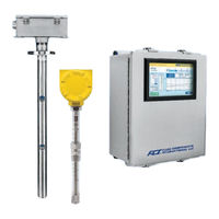
FCI MT100 Installation, Operation And Maintenance Manual (160 pages)
Multipoint Flow Meter
Brand:
FCI
| Category:
Measuring Instruments
| Size: 18.48 MB
Table of Contents
Table of Contents
3
List of Figures
5
1 General
9
Description
9
Theory of Operation
9
Safety Instructions
9
Order Verification
10
Equipment Nameplate
10
Specifications
11
2 Installation
13
Receiving/Inspection
13
Pre-Installation Procedure
13
Figure 1 - MT100M: Multipoint Flow Element Showing Flat Area, Duct Mount (Side Mounted Horizontal Configuration Shown)
14
Figure 2 - MT100M: Multipoint Flow Element Showing Flat Area, Flange Mount
15
Figure 3 - MT100S: Single Point Flow Element Showing Flat Area, Flange Mount
15
Install Flow Element
16
Figure 4 - Duct Flange Mounting, Dimensions, and Mounting Hardware
17
Figure 5 - Duct Flange Mounting, End Support Hardware (Optional)
18
Figure 6 - Alternative Duct Flange Mounting, Dimensions and Mounting Hardware
19
Figure 7 - Alternative Duct Flange Mounting, End Support Hardware (Optional)
20
Figure 8 - Single Point, Fixed RF Flange Process Connection
21
Figure 9 - Multipoint, RF Flange Process Connection (High Temp Shown)
22
Figure 10 - Multipoint Flanged Sensor Probe Example Installation
23
Figure 11 - Multipoint Flanged Probe End Support Detail
23
Figure 12 -Single Point, Fixed 1" Welded NPT Process Connection
24
Figure 13 - Multipoint, 2" NPT Process Connection (Low Temp Shown)
24
Figure 14 - Compression Fitting Mounting Dimensions
25
Table 1 - Compression Fitting Material
25
Figure 15 - Compression Fitting Process Connection (Optional Flange Shown)
26
Figure 16 - Low Pressure Retractable Packing Gland, NPT Process Connection Shown
27
Figure 17 - Medium Pressure Retractable Packing Gland, Flange Process Connection Shown
28
Figure 18 - Multiple Single Point Probe Installation (Packing Gland Shown)
29
Install Flow Transmitter
30
Figure 19 - MT100 Remote Transmitter Enclosure Outline Drawing
30
Wiring
31
Figure 20 - Bus Configuration 0.100" Jumper Headers
31
Table 2 - Interconnecting Cable Minimum Conductor Size
31
Figure 21 - MT100 Electronics Enclosure Label
32
Figure 22 - Flow Element Connections
33
Figure 23 - Input Power and I/O Connections
34
Figure 24 - Single Connection and Multidrop HART Setups
35
Figure 25 - Modbus Wiring
36
Table 3 - Modbus Line Configuration Jumpers
36
Figure 26 - Fieldbus/Profibus Wiring
37
Table 4 - J11 Relay Contacts Pinout
37
Figure 27 - Sink Output
38
Figure 28 - Source Output
38
Cabling Entry
40
Figure 29 - Cable Gland Installation
40
3 Operation
41
Introduction
41
Startup and Commissioning
41
Figure 30 - MT100 Normal Process Display Screen
41
Data Logging
42
Figure 31 - Microsd Card Socket J7 Location
42
Figure 32 - SD Card Data Logging Example Screen (MT100 Configuration Software)
43
Flow Damping
44
Figure 33 - Chart: Flow Output over Time with Various Flow Damping Values
44
CEMS Operation (Option)
45
Figure 34 - CEMS Option, Specific HMI Front Panel Display Elements
45
Touch Screen Calibration
47
Multi-Input System Operation
47
Figure 35 - Process Screen Showing Touch Screen Calibration Required
47
Using Digital Outputs
49
Explanation of Non-Zero Based and Zero Based Calibration
50
Delta R Table
50
Figure 36 - Zero Based Calibration
50
HART Operation
51
Table 5 - MT100 HART Process Variables
51
Figure 37 - Field Communicator Easy Upgrade Utility, Import DD
52
Table 6 - MT100 HART Device Registration Information
52
HART Command List Reference
55
Table 7 - HART Universal Commands
55
Table 8 - HART Common Practice Commands
63
Table 9 - MT100 HART Device Specific Command Groupings
66
Table 10 - HART Device Specific Commands
66
Table 11 - Command Status Bytes, Bit Assignments
77
Table 12 - Command 48, Additional Device Status Bytes Bit Assignments
78
Table 13 - HART Engineering Units Codes
79
Extended Operation Modes
80
Figure 38 - Extended Operating Mode Status on HMI Front Panel Display (EGS Shown)
80
Figure 39 - Connections for External Input Flow Adjust (EIA)
81
Figure 40 - Connections for External MT100 Flow Input (EFI)
81
Modbus Operation
82
Figure 41 - MT100 Configuration Software Output Tab with Modbus Selected
82
Figure 42 - MT100 Configuration Software Modbus Tab, Serial Interface Configuration
83
Table 14 - MT100 Modbus Function Codes
83
Table 15 - MT100 Modbus Process Data
84
Figure 43 - Modscan32, Data Definition
85
Table 16 - Modbus Service Data
85
Figure 44 - Modscan32, Serial Interface and Transmission Mode Configuration
86
Figure 45 - Modscan32 Connected to Modbus Device with Registers 4111 and 4112 on Display (Totalizer 1 Count)
86
Figure 46 - Modscan32 Connected to Modbus Device with Registers 4113 and 4114 on Display (Rollover Count)
87
Figure 47 - Modscan32 Connected to Modbus Device with Register 4115 on Display (Ceiling Value)
87
Figure 48 - Modscan32 Connected to Modbus Device with Register 4117 on Display (Totalizer Reset)
88
Figure 49 - Modscan32 Connected to Modbus Device with Register 4118 on Display (Totalizer Start/Stop)
88
Table 17 - Modbus Engineering Units Codes
89
Table 18 - CORE Fault Register Definitions
90
Table 19 - Devices (Sensor X) Status Codes #1 Register
91
Table 20 - Devices (Sensor X) Status Codes #2 Register
91
Table 21 - Devices (Sensor X) Status Codes #3 Register
92
4 Maintenance
93
Introduction
93
General Maintenance
93
Power Fuse Replacement
94
Lithium Battery Replacement
94
Figure 50 - Lithium Coin Cell Battery (CR2450) Location
94
Table 22 - Power Fuse Summary
94
5 Troubleshooting
95
Troubleshooting Equipment
95
Non-Maintenance Observations
95
General Function Check
97
Figure 51 - NAMUR Fault
97
Figure 52 - NAMUR Output Level Selection
98
Table 23 - Fatal Faults that Trigger NAMUR
98
Troubleshooting the Flow Element
99
Table 24 - Flow Element Resistance Measurements (in Ohms) Taken from Remote Electronics
99
Table 25 - Flow Element Resistance (in Ohms) at the Local Enclosure (MT100S, Single Sensor Application)
99
Verification of the Electronics
100
Table 26 - Flow Element Resistance (in Ohms) at the Local Enclosure (MT100M, Multipoint Sensor Application)
100
Table 27 - Instrument Power Supply Voltages
100
Safety Instructions
101
Delta R Check
101
Figure 53 - DMM Hookup to Measure 4-20 Ma Output
101
Heater Current Check
102
Allowable Limits
102
Table 28 - Heater Current
102
Defective Parts
103
Customer Service
103
Figure 54 - Connecting FES-200 to MT100 Transmitter
103
Figure 55 - MT100 Decade Box Wiring
103
Appendix Adrawings
105
Table 29 - MT100 Drawings in Appendix A
105
Appendix Bglossary
145
Abbreviations
145
Definitions
145
APPENDIX Chmi MENU OUTLINE (V1.09)
147
Appendix Dapproval Information
149
Appendix Ecustomer Service
155
Advertisement
Advertisement
Related Products
FCI MT86
FCI MT86HT
FCI MagicRound
FCI FLT93B
FCI FLT93C
FCI Categories
Measuring Instruments
Plumbing Product
Switch
Smoke Alarm
Dispenser
More FCI Manuals
Login
Sign In
OR
Sign in with Facebook
Sign in with Google
Upload manual
Upload from disk
Upload from URL