Table of Contents
Advertisement
Quick Links
ST50 MASS FLOW METER
Installation and Operation Guide
Pre-Installation
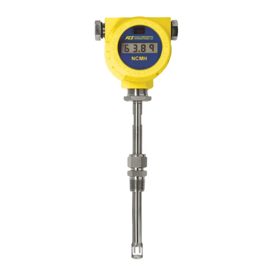
The ST50 can be specified with integral or remote electronics. The flow element has a serial number etched into the side of the
extension pipe as shown on Figure A. The transmitter circuit card has a serial number noted on the board as shown in Figure B. The
flow sensor and transmitter circuit have been calibrated as a matched set and should be paired together in service unless otherwise
approved by a factory technician.
Flow Direction Alignment
All sensor elements have a flow arrow indicator marked on the element assembly at the reference flat. These flow elements have
been calibrated in a particular direction and are designed to be used in service with the flow arrow facing in the same direction as
flow in the pipe stream. See Appendix C for orientation and factory calibration details.
Flow Direction
FLOW
Serial Number
Figure A
Figure B
Recommended Straight Run
To optimize flow meter system performance, FCI recommends installation with a minimum of 20 pipe diameters upstream straight run
and 10 pipe diameters of downstream straight run. Where straight run limitations significantly reduce the available pipe diameters, FCI
utilizes Vortab flow conditioners to produce a transferable flow profile from the calibration installation to actual field installations.
FCI's proprietary AVAL software is available to make flow meter installation evaluations where straight run limitations are considered.
See Figure C for recommended installation.
Figure C
FCI flow meters may be installed with less than the recommended straight run, but may have performance limitations. FCI offers
Vortab flow conditioners for use in applications that have significant straight run limitations. FCI uses the AVAL application modeling
software to predict meter performance in each installation. AVAL outputs are available to review prior to order placement and will
indicate performance expectations both with and without Vortab Flow Conditioning.
1
Doc. No. 06EN003367 Rev. E
This page is subject to proprietary rights statement on last page
Advertisement
Table of Contents

Related Manuals for FCI ST50


Summary of Contents for FCI ST50
- Page 1 Pre-Installation The ST50 can be specified with integral or remote electronics. The flow element has a serial number etched into the side of the extension pipe as shown on Figure A. The transmitter circuit card has a serial number noted on the board as shown in Figure B. The flow sensor and transmitter circuit have been calibrated as a matched set and should be paired together in service unless otherwise approved by a factory technician.
- Page 2 Fluid Components International LLC ST50 Mass Flow Meter Specifications Instrument Insertion Length: Field adjustable lengths: 1" to 6" [25 mm to 152 mm]; 1" to 12" [25 mm to 305 mm]; Media Compatibility: Air, compressed air, and nitrogen or 1" to 18" [25 mm to 457 mm] Pipe/Line Size Compatibility: 23"...
-
Page 3: Installing Flow Element
The ST50 is available with both Teflon compression fitting ferrules and metal ferrules. While the Teflon ferrule configuration can be readjusted, it is possible that over tightening may result in permanent positioning or damage to the extension pipe and will make future adjustment difficult. - Page 4 Retractable Packing Gland Mounting A retractable packing gland, with ½" MNPT or ¾" MNPT threads and graphite or Teflon packing, is a process connection option. FCI single point flow meters are calibrated at the centerline of the process pipe. The flow element is properly mounted when the tip of the flow element is located .50 inches (13 mm) past the pipe centerline.
- Page 5 ST50 Mass Flow Meter Fluid Components International LLC 5. Tighten the packing nut until the internal packing is tight enough to prevent excess process leakage, but also allow the insertion probe to be inserted into place. For ball valve applications, open the ball valve after the packing nut has been tightened.
-
Page 6: Instrument Wiring
Input Power The ST50 is available with both VDC and VAC input power configurations. Customers selecting VDC input power will have a VDC input board only. Similarly, the VAC power board is supplied only with VAC powered units. In addition, both boards are marked for either DC or AC power. -
Page 7: Vdc Power Connection
ST50 Mass Flow Meter Fluid Components International LLC VDC Power Connection VAC Power Connection RS 232 Connection RS 232 Connection Figure G Figure H VDC Power VAC Power As Shown: As Shown: 18-36 VDC power connected with Gnd 85-265 VAC power connected with Gnd... -
Page 8: Pulse Output Activation
Pulse Output Setup The ST50 mass flow meter pulse output can be configured for either a pulse train (factory standard) for an external counter and/or flow rate indication or an alarm. The pulse output can be wired to use a source or sink outputs. The maximum frequency of the pulse output is 500 Hz. - Page 9 ST50 Mass Flow Meter Fluid Components International LLC Pulse Output Wiring Pulse Output Wiring Doc. No. 06EN003367 Rev. E This page is subject to proprietary rights statement on last page...
-
Page 10: Setup Interface
After configuring the serial port (and making the PC-to-instrument connections) start a communications session with the applicable serial port. Enter any of the meter’s single letter commands in the program’s terminal window to execute a function. See “Table 5. ST50 List of Single Letter Commands”... -
Page 11: Startup And Commissioning
ST50 Mass Flow Meter Fluid Components International LLC Startup and Commissioning Verify that all input power and output signal wiring is correct. Apply power to the instrument. Observe that the instrument initializes in the normal operation mode with all outputs active and the display (if so equipped) showing flow with the factory-set flow unit. - Page 12 1 SCFM, the new span (20 mA) must be equal to or less than 100 SCFM. Some entries require a Factory pass code. If this occurs contact FCI Field Service to continue programming the instrument. The instrument will prompt the user when this is necessary. Do not change any parameters that require this code unless there is an absolute understanding of the instrument's operation.
-
Page 13: "V" Menu Output Configuration Setup
ST50 Mass Flow Meter Fluid Components International LLC “V” Menu Output Configuration Setup Use the V menu to set up the 4-20 mA analog outputs (including NAMUR configuration) and source/sink (pulse) outputs. Note: The display comes up to the last setting saved and stays for 2 seconds. If N or [ENTER] is entered, the menu proceeds to the Pulse out. - Page 14 Fluid Components International LLC ST50 Mass Flow Meter The last saved mode of the next menu item displays: “Sample Period” ...followed by the prompt: “Change? (Y/N)>” Respond with “Y” to enter a sample period value from 0.5 to 5 seconds.
-
Page 15: Maintenance
Fluid Components International LLC Maintenance The FCI instrument requires little maintenance. There are no moving parts or mechanical parts subject to wear in the instrument. The sensor assembly which is exposed to the process media is composed of 316 SS and Hastelloy C. - Page 16 Fluid Components International LLC ST50 Mass Flow Meter INTENTIONALLY LEFT BLANK Doc. No. 06EN003367 Rev. E This page is subject to proprietary rights statement on last page...
-
Page 17: Troubleshooting
ST50 Mass Flow Meter Fluid Components International LLC Troubleshooting Application Verification After verifying that the flow meter is functioning, review the application parameters as shown below to verify the calibration matches the process media. Equipment Needed Flow Instrument Calibration Data... - Page 18 The instrument uses a set of predetermined calibration parameters to process flow signals. Most of these parameters should not change. Included with the instrument is a data package containing the ST50 Delta R Data Sheet. This contains the calibration parameters stored in the flow transmitter at the factory. To verify that these parameters have not changed, complete the following: Identify the appropriate Delta R data sheets by serial number of the instrument.
- Page 19 Unscrew the clear cover on the fuse and pull the fuse out of the fuse holder. Check the fuse for continuity. If fuse reads open, replace with equivalent component (FCI part no.
- Page 20 Fluid Components International LLC ST50 Mass Flow Meter Step 3 Verify sensor element continuity and resistance. Remove sensor element cable from the bottom of the control circuit assembly. Note that two of the wires have a red stripe and are located closest to the interconnecting cable header.
- Page 21 Note the orientation of the sensor element plug connected to the circuit board. Unplug the connector from the board. 4. Connect the resistance decade box to the electronics as per the appropriate diagram for the ST50. Connect the 250-ohm resistor across the 4-20 mA output terminals.
- Page 22 Fluid Components International LLC ST50 Mass Flow Meter INTENTIONALLY LEFT BLANK Doc. No. 06EN003367 Rev. E This page is subject to proprietary rights statement on last page...
-
Page 23: Appendix A - Approval Information
ST50 Mass Flow Meter Fluid Components International LLC Appendix A - Approval Information Information Doc. No. 06EN003367 Rev. E This page is subject to proprietary rights statement on last page... - Page 24 Fluid Components International LLC ST50 Mass Flow Meter INTENTIONALLY LEFT BLANK Doc. No. 06EN003367 Rev. E This page is subject to proprietary rights statement on last page...
-
Page 25: Appendix B - List Commands
ST50 Mass Flow Meter Fluid Components International LLC Appendix B - List Commands Table 5. ST50 List of Single Letter Commands COMMAND COMMAND MNEMONIC FUNCTION COMMAND DECRIPTION AvgDelta_r, AvgRef Delta_r, Ref_r Tcdelta_r, Ref_r Diagnostics Kfactors Clear FlashEE, Boxcar Count, ADC to Ohms Cal... - Page 26 Fluid Components International LLC ST50 Mass Flow Meter Table 6. ST50 List of CLI Commands, Cont. Command Line Password: 357 Doc. No. 06EN003367 Rev. E This page is subject to proprietary rights statement on last page...
- Page 27 ST50 Mass Flow Meter Fluid Components International LLC Note: When invoking a Write Function, separate the Command characters and the data value with a space. All Read and Write Functions are completed with a <CR>. To exit CLI, press <CR> following the last Command <CR>.
- Page 28 Fluid Components International LLC ST50 Mass Flow Meter INTENTIONALLY LEFT BLANK Doc. No. 06EN003367 Rev. E This page is subject to proprietary rights statement on last page...
-
Page 29: Appendix C - Drawings
ST50 Mass Flow Meter Fluid Components International LLC Appendix C - Drawings Doc. No. 06EN003367 Rev. E This page is subject to proprietary rights statement on last page... - Page 30 Fluid Components International LLC ST50 Mass Flow Meter FLUID COMPONENTS INTERNATIONAL LLC FLUID COMPONENTS INTERNATIONAL LLC Doc. No. 06EN003367 Rev. E This page is subject to proprietary rights statement on last page...
- Page 31 ST50 Mass Flow Meter Fluid Components International LLC Doc. No. 06EN003367 Rev. E This page is subject to proprietary rights statement on last page...
- Page 32 Fluid Components International LLC ST50 Mass Flow Meter FLUID COMPONENTS INTERNATIONAL LLC FLUID COMPONENTS INTERNATIONAL LLC Doc. No. 06EN003367 Rev. E This page is subject to proprietary rights statement on last page...
-
Page 33: Appendix D - Customer Service
Attn: Customer Service Department By Phone Contact the area FCI regional representative. If a field representative is unable to be contacted or if a situation is unable to be resolved, contact the FCI Customer Service Department toll free at 1 (800) 854-1993. - Page 34 Contact an FCI field representative to request field service. A field service technician is dispatched to the site from either the FCI factory or one of the FCI representative offices. After the work is complete, the technician completes a preliminary field service report at the customer site and leaves a copy with the customer.
- Page 35 ST50 Mass Flow Meter Fluid Components International LLC Doc. No. 06EN003367 Rev. E This page is subject to proprietary rights statement on last page...
- Page 36 Fluid Components International LLC ST50 Mass Flow Meter Doc. No. 06EN003367 Rev. E This page is subject to proprietary rights statement on last page...
-
Page 37: Instrument Warranty
ST50 Mass Flow Meter Fluid Components International LLC Instrument Warranty Goods furnished by the Seller are to be within the limits and of the sizes published by the Seller and subject to the Seller’s standard tolerances for variations. All items made by the Seller are inspected before shipment, and should any of said items... - Page 38 1755 La Costa Meadows Drive, San Marcos, California 92078 USA - 760-744-6950 - 800-854-1993 - Fax 760-736-6250 © Copyright 2018 by Fluid Components International LLC. All rights reserved. FCI is a registered trademark of Fluid Components International LLC. Information subject to change without notice.
Need help?
Do you have a question about the ST50 and is the answer not in the manual?
Questions and answers