FCI ST100 Series Configuration Software Manual
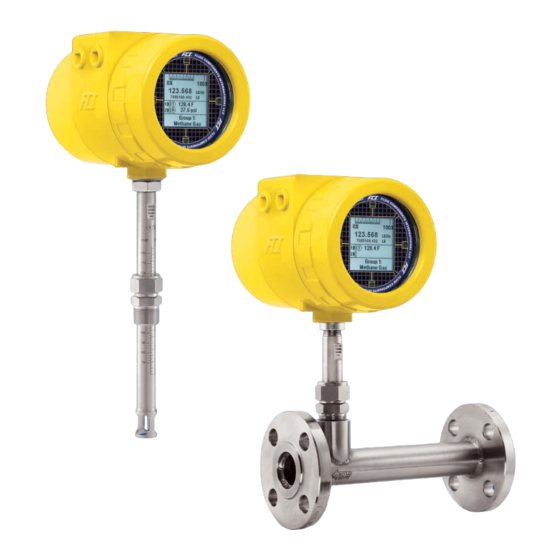
Thermal mass flow meter
Hide thumbs
Also See for ST100 Series:
- Installation, operation & maintanance manual (106 pages) ,
- Operation manual (44 pages) ,
- Manual (36 pages)

Related Manuals for FCI ST100 Series


Summary of Contents for FCI ST100 Series
- Page 1 Configuration Software Manual ST100 Series Thermal Mass Flow Meter Fluid Components International LLC (FCI). All rights reserved.
- Page 2 Any other use is strictly prohibited without the prior written consent of FCI. © Copyright 2017 by Fluid Components International LLC. All rights reserved. FCI is a registered trademark of Fluid Components International LLC. Information subject to change without notice.
-
Page 3: Table Of Contents
ST100 Series Configuration Software 06EN003403 Rev. C Table of Contents Introduction ............................................1 Installation ............................................1 Running the PC Configuration Application ..................................1 Configuration Software Basics ......................................3 Password Protection........................................3 Basic Setup Tab Screens ........................................4 Advanced Setup Tab Screens ......................................7 Configuration Tab Screens ........................................9 Diagnostics Tab Screens ........................................13... - Page 4 06EN003403 Rev. C ST100 Series Configuration Software List of Tables Table 1 – Basic Setup Tabs ......................................4 Table 2 – Advanced Setup Tabs .......................................7 Table 3 – Configuration Tabs ......................................10 Table 4 – Diagnostics Tabs ......................................13 Table 5 – Factory Tabs ........................................15...
-
Page 5: Introduction
The ST100 Configuration software is a Windows PC application that lets the user easily set up and configure the ST100 Multipoint Flow Meter prod- ucts. Use this tool for all instrument commissioning activity. Note that the software application serves both ST100 Series and MT100 product lines. -
Page 6: Figure 2 - Welcome Screen
ST100 Series Configuration Software USB Connect Button Ethernet Connect Button C01381-1-2 Figure 2 – Welcome Screen Once connected, the application window shows the Process Data screen as shown in the figure below. The displayed information, which is the same as that shown on the HMI front panel display, includes the following: •... -
Page 7: Configuration Software Basics
ST100 Series Configuration Software Configuration Software Basics The ST100 is set up using a configuration menu arranged in a hierarchical tree structure on the left side of the window. Select a menu item to see the related tabs on the right side of the window. Within the tab area parameter data is typically organized into one or more data fields, which are set off with a thin divider line or a thin box outline. -
Page 8: Basic Setup Tab Screens
ST100 Series Configuration Software Basic Setup Tab Screens Select the Basic Setup branch on the menu tree to access basic setup items. The Groups tab is the first of several tabs across the top of the screen. Each tab provides a particular menu within the Basic Setup branch. -
Page 9: Figure 6 - Example Units Tab (Basic Setup)
ST100 Series Configuration Software Figure 6 – Example Units Tab (Basic Setup) Figure 7 – Example Pipe Size Tab (Basic Setup) Figure 8 – Example Alarms Tab (Basic Setup) Fluid Components International LLC... -
Page 10: Figure 9 - Example Sd Card Logging Tab (Basic Setup)
ST100 Series Configuration Software Figure 9 – Example SD Card Logging Tab (Basic Setup) Figure 10 – Example Totalizer Tab (Basic Setup) Figure 11 – Example Pressure Offset Tab (Basic Setup) Fluid Components International LLC... -
Page 11: Advanced Setup Tab Screens
Lets users download a full calibration to their ST100 via a text file. Download Calibration Contact FCI to obtain the .txt file that was generated by the factory User linearization software (Cal2). -
Page 12: Figure 13 - Example Ethernet Tab (Advanced Setup)
ST100 Series Configuration Software Figure 13 – Example Ethernet Tab (Advanced Setup) Figure 14 – Example Data and Time Tab (Advanced Setup) Figure 15 – Example Download Calibration Tab (Advanced Setup) Fluid Components International LLC... -
Page 13: Configuration Tab Screens
ST100 Series Configuration Software Figure 16 – Example Reboot Device Tab (Advanced Setup) Configuration Tab Screens Select the Configuration branch on the menu tree to access configuration setup items. The Output tab is the first of several tabs across the top of the screen. -
Page 14: Figure 18 - Example 4-20Ma User Tab (Configuration)
ST100 Series Configuration Software The table below summarizes the tabs within the Configuration branch. Table 3 – Configuration Tabs Tab Name Tab Description Password Level Analog Output board: Sets 4-20 mA channel configuration and Frequency Output and Pulse output configuration. -
Page 15: Figure 19 - Example Modbus Tab (Configuration)
ST100 Series Configuration Software Figure 19 – Example Modbus Tab (Configuration) Figure 20 – Example Extended Op. Mode Tab (Configuration) Figure 21 – Example Group Switch Setup Tab (Configuration) Fluid Components International LLC... -
Page 16: Figure 22 - Example Ast Power Mode Tab (Configuration)
ST100 Series Configuration Software Figure 22 – Example AST Power Mode Tab (Configuration) Fluid Components International LLC... -
Page 17: Diagnostics Tab Screens
ST100 Series Configuration Software Diagnostics Tab Screens Select the Diagnostics branch on the menu tree to access diagnostic items. The Status tab is the first of several tabs across the top of the screen. Each tab provides a particular menu within the Diagnostics branch. The table below summarizes the tabs within the Diagnostics branch. -
Page 18: Figure 24 - Example Fault Log Tab And Example Fault Log List (Diagnostics)
ST100 Series Configuration Software Figure 24 – Example Fault Log Tab and Example Fault Log List (Diagnostics) Figure 25 – Example idR Scheduled Tests Tab and Example idR On-Demand Test Results Display (Diagnostics) Figure 26 – Example idR Test Logs Tab and Example idR Test Log List (Diagnostics) -
Page 19: Factory Tab Screens
ST100 Series Configuration Software Factory Tab Screens The Factory branch on the menu tree provides factory-only setup items. Only the factory or its respresentatives can change data in this group. Table 5 – Factory Tabs Tab Name Tab Description Password Level Factory Parameters Factory use only. -
Page 20: Figure 29 - Example 4-20Ma Factory Tab (Factory)
ST100 Series Configuration Software Figure 29 – Example 4-20mA Factory Tab (Factory) Figure 30 – Example Options Tab (Factory) Figure 31 – Example HART Tab (Factory) Fluid Components International LLC... -
Page 21: Figure 32 - Example Memory Tab (Factory)
ST100 Series Configuration Software Figure 32 – Example Memory Tab (Factory) Figure 33 – Example Reset idRs Tab (Factory) Fluid Components International LLC... -
Page 22: Fe1-Fe2 Process Data
FE1-FE2 Process Data Depending on the system configuration (options) the application menu tree shows FE process data for either FE1 only or, for ST100 Series models with dual point flow elements, FE1 and FE2. For the purpose of this discussion we will focus on FE1—the FE2 process data screen is similar. Select the FE1 Process Data branch on the menu tree. -
Page 23: Parameter Reports
ST100 Series Configuration Software Parameter Reports A Parameter Reports screen (under Group Parameters in the menu tree) displays the calibration and configuration information saved in the ST100 unit for a particular calibration group numbered 1-5. Selecting a parameter report for a particular calibration group displays that group’s info/data. -
Page 24: Customer Service/Technical Support
Attn: Customer Service Department By Phone Contact the area FCI regional representative. If a field representative is unable to be contacted or if a situation is unable to be resolved, contact the FCI Customer Service Department toll free at 1 (800) 854-1993. - Page 25 ST100 Series Configuration Software NOTES Fluid Components International LLC...
- Page 26 (and does not include manufacture or processing uses). Any other use is strictly prohibited without the prior written consent of FCI. © Copyright 2017 by Fluid Components International LLC. All rights reserved. FCI is a registered trademark of Fluid Components International LLC. Information subject to change without notice.
Need help?
Do you have a question about the ST100 Series and is the answer not in the manual?
Questions and answers