Table of Contents
Advertisement
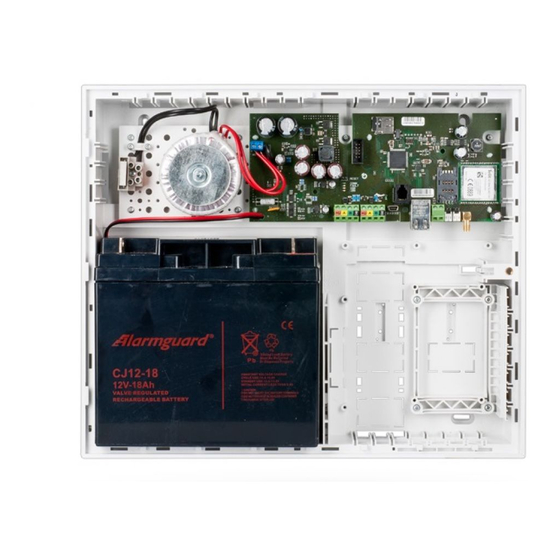
JA-101K(-LAN)(-LAN3G) and JA-106K(-3G)
A control panel is a fundamental part of the JABLOTRON 100 series alarm system and is designed to protect
small, medium or large premises and complies with security grade 2 requirements. The control panel has BUS
and/or wireless device (when the system is equipped with a radio module) compatibility. It is recommended that
only JABLOTRON 100 devices are used with the system. Proper functionality cannot be guaranteed when using
third party devices.
Caution: The JABLOTRON 100 security system can only be installed by a trained technician with a valid
certificate issued by an authorized distributor.
The manual is intended for trained technicians and is valid for control panel firmware LJ60418 and
MD60418 and the configuration software F-Link 1.4.0 or higher.
Contents
1
Basic description and definitions ................................................................................................................ 4
1.1
Basic system configuration requirements ........................................................................................... 7
1.2
Access codes and their default settings ............................................................................................. 9
1.2.1
Change of access codes ............................................................................................................ 9
1.2.2
Security access codes and RFID devices ................................................................................. 10
1.2.3
Regular system check (maintenance) ....................................................................................... 10
2
System size............................................................................................................................................. 12
2.1
External size .................................................................................................................................... 12
2.2
Internal size (system range) ............................................................................................................. 12
2.2.1
Configuration and splitting ........................................................................................................ 13
3
Types of control panels, utility parameters ............................................................................................... 14
3.1
Description of JA-101K(-LAN)(-LAN3G) / JA-101KR(-LAN)(-LAN3G) ............................................... 15
3.2
Description of JA-106K(-3G) / JA-106KR(-3G) ................................................................................. 16
3.3
Indication LEDs on the control panel board ...................................................................................... 18
3.4
Additional Connectors on the control panel PCB .............................................................................. 18
3.5
Connection terminals on the control panel PCB................................................................................ 18
4
Before system installation ........................................................................................................................ 19
5
Installation of BUS devices ...................................................................................................................... 20
5.1
JA-100 BUS ..................................................................................................................................... 20
5.2
BUS cables...................................................................................................................................... 20
5.3
BUS layout ...................................................................................................................................... 21
5.4
BUS branching and splitting ............................................................................................................. 21
5.5
BUS length and numbers of connected devices ............................................................................... 21
5.6
Calculation of line losses ................................................................................................................. 22
5.7
Example of a voltage loss calculation: .............................................................................................. 22
5.8
Example of calculation of BUS consumption to back-up the system ................................................. 23
5.9
Power supply requirements .............................................................................................................. 24
5.10
Backup requirements ....................................................................................................................... 24
5.11
BUS isolation ................................................................................................................................... 24
5.12
Use of existing cabling in refurbishment projects. ............................................................................. 25
6
Use of wireless devices ........................................................................................................................... 25
6.1
Installation of a JA-11xR radio module ............................................................................................. 25
6.2
Installation of wireless devices - enrollment mode ........................................................................... 25
7
Switching the system ON......................................................................................................................... 26
8
System configuration ............................................................................................................................... 26
8.1
The system profiles .......................................................................................................................... 26
8.2
Control panel operation modes ........................................................................................................ 30
8.3
Authorisation of users ...................................................................................................................... 31
8.4
System optional parameters ............................................................................................................ 31
8.4.1
Enrolling and erasing devices ................................................................................................... 33
8.4.2
List of applicable reactions ....................................................................................................... 34
8.4.3
Limitation of false alarms .......................................................................................................... 35
8.5
Types of alarms ............................................................................................................................... 37
Security System Control Panels
Advertisement
Table of Contents


Need help?
Do you have a question about the JA-101K and is the answer not in the manual?
Questions and answers
Jablotron JA-106K-3G Lähetätkö akun vaihdon ohjeet.
To replace the battery in the Jablotron JA-101K:
1. Switch off the mains power supply.
2. Open the control panel housing.
3. Disconnect the battery supply leads (note polarity: red +, black -).
4. Remove the old battery from the housing.
5. Insert the new battery and fix it using self-sticking blocks or a strap.
6. Connect the supply leads to the new battery, ensuring correct polarity.
7. Close the housing.
8. Switch on the mains power and check the LED indicators.
This answer is automatically generated