Table of Contents

Related Manuals for jablotron OASiS JA-82KRC


Summary of Contents for jablotron OASiS JA-82KRC
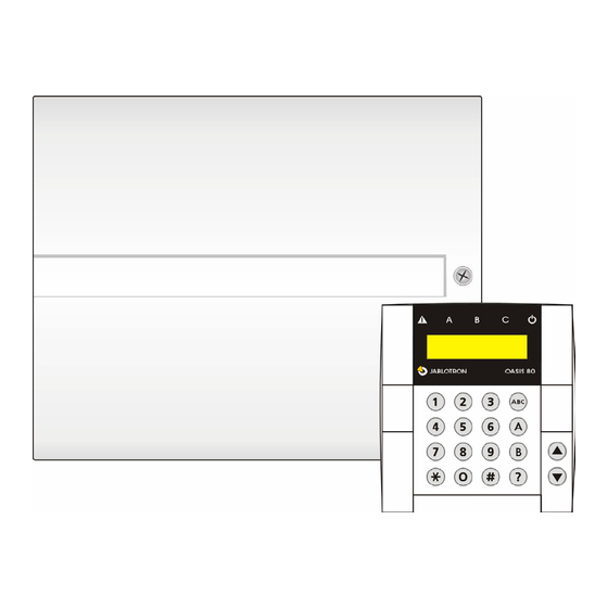
- Page 1 JA-82KRC “OASiS” Control panel installation manual This manual is valid for control panel JA-82KRC. The control panel can be configured by a PC running OLink software. Installation manual: OASiS security system JA-82KRC 1 / 21 MKH51100_OS2...
-
Page 2: Table Of Contents
Contents: 12.21. Wireless siren alarm enabled (IW and EW) ...... 13 Control panel architecture ........3 12.22. Auto-bypass user approval via the ∗ key......13 1.1. Main features ...............3 12.23. Final-door detectors............13 1.1.1. Modes ................4 12.24. Partial setting (arming) or system splitting ......14 1.2. -
Page 3: Control Panel Architecture
o The control panel does not allow for the simultaneous System installation shall only be undertaken by qualified connection of both a wired and a wireless input to the technicians holding a training certificate issued by an same address. Connecting to a wired input automatically authorized distributor. -
Page 4: Modes
• The control panel has two alarm outputs: IW = internal 2.1. Power inlet (indoor) warning and EW = external (outdoor) warning. Both The control-panel power cable should only be installed by a these signals are also available as wireless signals. person holding a sufficient electro-technical qualification. -
Page 5: Control Panel Connectors And Terminals
o Stand-by (untriggered) input zone (if any) must have 1 Radio module kΩ. connector o Up to five normally-closed door/window contacts can be connected in series to enable one hard-wired input to be Memory socket used for multiple contacts with each contact having a 1kΩ... -
Page 6: Back-Up Battery
“1” key, then use the arrow keys to select the desired address. Then disconnect the It is possible to use a Jablotron-brand 12V back-up battery in keypad battery and reconnect it. the control panel with a capacity of 2.2 Ah. The capacity to use... -
Page 7: Closing The Control Panel Cover
Warning: close to the control panel (closer than 2 meters is not • After a RESET, all wireless devices are erased from the permitted), • To re-enroll a device, first disconnect its battery. Then wait control panel and all user codes and access cards are “forgotten”. -
Page 8: Erasing Enrolled Devices
11.5. Erasing enrolled devices Alternatively you could carry the wireless keypad close to the module to perform enrollment. 1. The control panel must be in Service Mode. If it is not, then • The control panel can be enrolled to the desired number of enter ∗0 service code (factory default: 8080). - Page 9 Radio interference indication 261 = YES 260 = NO 30s or longer 271 = YES 270 = NO Radio communication supervision RESET enabled 281 = YES 280 = NO (Un)setting the master control Master control panel enrollment to a sub control The sequence triggers panel will (un)set the sub control p.
- Page 10 Engineer reset 668x 6851 = YES 6850 = N0 Annual check requirement display 6901 = YES 6900 = NO 690x If enabled then 12 months after exiting Service Mode an annual technical check request is displayed on the keypad unit (mobile phone &...
-
Page 11: Exit Delay Time
Unsplit system Split system 12.2. Exit delay time Completely (ABC) set Alarm A = PG on An exit delay time occurs while setting (arming) the system. = PG on During this time period delayed or next-delayed detectors can be Anything set = PG on Alarm B = PG on triggered without an alarm occurring. -
Page 12: Reset Enabled
repeated often. recommend disabling 12.12. Control panel enrollment to UC or AC communications supervision in cases like this. modules or to a sub control panel Factory default setting: supervision disabled. Keying in sends an enrollment signal to enroll the control panel to UC-82 or AC-82 receiving modules (see 11.6). -
Page 13: Exit Delay Beeps
• If the unconfirmed entrance delay is confirmed by an instant 12.21. Wireless siren alarm enabled (IW and EW) detector it will trigger an internal warning alarm immediately This setting is for enabling and disabling wireless sirens in the (e.g. an internal siren) and if the entrance delay times out system: then an external alarm will be triggered. -
Page 14: Partial Setting (Arming) Or System Splitting
• After entering a request to set the system, an exit delay of devices, access codes and keyfobs to various sections of the system has no effect in this mode. between 30 to 270 seconds will begin and be indicated. •... -
Page 15: Permanent Alarm Status Display For A Set System
∗ ∗ • The feature is supported when a JA-80Y version XA61008 or higher, • In addition to controlling the PG outputs using keys 8 and 9, PG outputs can also be controlled by access codes, access cards, or a JA-80V version XA64005 or higher is installed. keyfobs and detector signals (see 12.40 and 12.41 for details). -
Page 16: Higher Control-Panel Receiver-Sensitivity
6 9 3 1 audible panic alarm is the section 1 = A, 2 = B, 3 = C (only has an effect if partial setting or system splitting is used Note: If the sequence 370 is used, panic alarms are silent if any section –... -
Page 17: Code/Card Reactions And Section Assignment
• If a code/card has a natural reaction, i.e. r=1, then its reaction Sets its own section of the system is set,unset,set etc. (the same as reaction r=9 in table 2). The value of the s parameter determines which output PG output is controlled: s= 1= PGX, s=2=PGY •... -
Page 18: Go To Maintenance Mode
12.45. Go to maintenance mode Factory default setting: in addresses 01 to 50 there is the text “Device”. Other default text: “Control panel”, “Keypad”, By entering 292 while in Service Mode the system switches to “Communicator”, “Master code”, users 01 to 50 “Code”,”ARC maintenance mode. -
Page 19: Functions Beginning With The ∗ Key
∗0 hot key for setting the entire system (all sections To enter Service Mode (∗0 SC – factory default 8080) A, B & C) or to enter maintenance mode (∗0 MC – factory default hot key for setting section A (e.g. afternoon 1234) The ∗... -
Page 20: Setting And Unsetting (Arming/Disarming) The System
is programmed or not, and the B indicator showing whether a 13.3. Setting and unsetting (arming/disarming) card is programmed or not. the system 4. To exit this code/card display mode press the # key. The system can be set and unset from a keypad, a keyfob or 5. -
Page 21: Basic Guidance For Installers
Electrical safety EN 60950-1 Can be operated according to ERC REC 70-03 * these signals are also transmitted wirelessly to AC and UC receiver modules. Jablotron Ltd. hereby declares that the JA-82KRC “OASiS“ control panel compliance with essential requirements and other relevant provisions of Directive 1999/5/EC.
Need help?
Do you have a question about the OASiS JA-82KRC and is the answer not in the manual?
Questions and answers