Table of Contents
Advertisement
Quick Links
Advertisement
Table of Contents

Related Manuals for jablotron OASiS JA-83K


Summary of Contents for jablotron OASiS JA-83K
-
Page 2: Table Of Contents
Contents: Control panel architecture........3 6.24 Automatic summer time (daylight saving time) 6.25 Pulse reaction of tamper sensors Required system configuration 6.26 Operating the PG outputs using 8 and 9 Preparing the control panel for installation ..3 6.27 Permanent alarm status display for a set system Control panel main board........ -
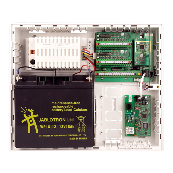
Page 3: Control Panel Architecture
This manual is valid for control panel JA-83K The control panel can be configured by a PC running OLink software. (position 4) must always be connected if the second module is to operate. Device installation shall only be undertaken by qualified technicians holding... -
Page 4: Hard-Wired Inputs On The Main Board
terminals (max. 0.5A). The IW output status is also transmitted for the wireless IW siren. 1 2 3 4 The difference between the internal warning (IW) output function and the external warning (EW) one lies in their behaviour during the entrance delay period. -
Page 5: Control Panel Memory Chip
If you are installing a GSM communicator (Y) and there is a strong GSM Backup battery connection signal in the place of installation, the self-adhesive antenna can be attached It is possible to use a 12V gel cell backup battery, with a capacity of up to directly to the flat surface of the holder. -
Page 6: Oasis Wireless Devices
g) check whether the keyboard functions in the place where you Signal strength measuring intend to install it and then install its plastic rear part. 1. The control panel must have its antenna connected and it must be *) The keypad comes with English texts from production – these can be in Service mode (If this is not the case, enter *0 service code (factory changed to other languages –... -
Page 7: Exit Delay Time
The control panel must have its antenna connected and it must be in Notes: Service mode (If this is not the case, enter *0 service code (factory The PGX and PGY outputs are not only provided as control panel default: 8080). -
Page 8: Master Code Reset
If it is desired to control a sub control panel from a master control panel alarm will not be caused but the control panel will record a so-called (i.e. setting/unsetting), it is possible to enroll a JA-8x OASiS master control unconfirmed alarm. -
Page 9: Sirens Always Sound During Audible Alarms
Note: In JA-80L wireless sirens, this function can be individually enabled for door detector is connected should be assigned to the addresses which each siren. (see the siren manual). you set with this sequence as belonging to final-door detectors. If a final-door detector is used for a garage door, no instant detectors Factory default setting: Hard-wired siren chirps disabled should be inside the garage. -
Page 10: Automatic Summer Time (Daylight Saving Time)
little of the system is set. This feature can be used to ignore this A keyfob can also be used for partial setting control. Buttons requirement if appropriate. can be programmed to set and unset the entire system, and ... -
Page 11: Only Single Alarm Indication
15th October 2007, the notification is displayed on the 1st October Notes: 2008.) The system has up to 50 user positions (01 to 50) each capable of When this notification is enabled, exiting Service Mode will cause a having an access code and an access card assigned to it. -
Page 12: Code/Card Reactions And Section Assignment
where nn is the user position from 01 to 50 fig. 11 continues r is the reaction index from 0 to 9 – see fig. Reaction Notes s is the section 1 = A, 2 = B, 3 = C (only has an effect in a split system –... -
Page 13: Changing The Service Code
Control panel Name of control panel (e.g. displayed if its cover is In standby mode, it shows the text “JABLOTRON”. A picture of size 128x48 opened) pixels can be loaded into the keypad . (Olink 1.4 or a higher version is... -
Page 14: Functions Beginning With The Key
Maintenance Mode 7.1.5 Functions beginning with the key The following functions are available to the user via the keypad: Maintenance mode can be entered using a master code or master card by entering: 1 sets the entire system (the same as key ABC)* 2 sets section A (the same as key A)* 0 MC... -
Page 15: Operating/Programming The System By Pc
Operating/programming the system by PC Basic guidance for installers The OASiS system can be operated and programmed locally using a PC Create an installation plan that sufficiently covers the building to be running OLink software. To connect the control panel to the PC use a protected. -
Page 16: Control Panel Technical Specifications
* these signals are also transmitted wirelessly to wireless sirens and AC and UC receiver modules. Jablotron Alarms a.s. hereby declares that the JA-83K “OASiS“ control panel is in compliance with the essential requirements and other relevant provisions of Directive 204/108/EC, 1999/5/EC 2006/95/EC. -
Page 17: Control Panel Programming Sequences
12 Control panel programming sequences Setting to Factory Function Sequence Options comply with Notes default EN-50131-1 devices enroll by connecting Entering enrollment mode Keys: their power (battery) except One wireless device (detector, keypad, key 1 and 7 = address keyfobs which enroll by fob, siren or sub control panel) can be enrolled scrolling... - Page 18 fig. 18 continues Setting to Factory Function Sequence Options comply with Notes default EN-50131-1 Entrance delay beeps 351 = YES 350 = NO Setting (arming) confirmation by wired-siren IW terminal only 361 = YES 360 = NO chirp Siren always sounds during audible alarms NO = siren only sounds if the 371 = YES 370 = NO...
- Page 19 fig. 18 continues Setting to Factory Function Sequence Options comply with Notes default EN-50131-1 When the detector is disabled Device reactions and section assignment nn = address 01 to 50 (r=0), the tamper sensor is not (detectors, key fobs, control panel and r = reaction: triggered, keypad inputs)
-
Page 20: Programming Access Codes And Cards
13 Programming access codes and cards Code name Amount Sequence Notes Only programmable Service Mode. Service 5 NC NC NC = code (must be entered tw ice) – a card cannot be used. Factory -default service code: 8080 ... - Page 21 Notes:...
Need help?
Do you have a question about the OASiS JA-83K and is the answer not in the manual?
Questions and answers