Table of Contents
Advertisement
Quick Links
Advertisement
Table of Contents

Related Manuals for LEGRAND 3440


Summary of Contents for LEGRAND 3440
- Page 1 Technical sheets...
- Page 2 ZIGBEE RADIO SYSTEM AUTOMATION BURGLAR ALARM TEMpERATURE CONTROL LOAD CONTROL MANAGEMENT AND CONSUMpTION DISpLAY VIDEO DOOR ENTRY SYTEM SOUND SYSTEM RESIDENTIAL STRUCTURED CABLING SYSTEM INTEGRATION AND CONTROL Contents MyHOME...
-
Page 3: Table Of Contents
Index ITEM N° PAGE ITEM N° PAGE ITEM N° PAGE 3440 3577 349313 3442 3578 349320 3444 3579 349321 3445 3581 349340 3448 4050 351200 3455 4072A 351300 3456 4072L 352200 3475 336904 352400 3476 342991 352500 3477 342992 352700... - Page 4 ITEM N° PAGE ITEM N° PAGE ITEM N° PAGE BMDI1001 F483 HA4589 BMSW1002 F500N HA4596 BMSW1003 F502 HA4597 E46ADCN F503 HA4598 E47/12 F520 HA4599 E47ADCN F521 HA4619 F522 HB4589 F401 F523 HB4596 F411/1N F524 HB4597 F411/1NC F550C6 HB4598 F411/2 F551 HB4599 F411/2NC F552...
- Page 5 ITEM N° PAGE ITEM N° PAGE ITEM N° PAGE HC4891 HS4610 L4610 HD4070 HS4611 L4611 HD4560 HS4613 L4611B HS4618 HD4565 L4613 HS4653/2 HD4577 L4618 HS4653/3 HD4578 L4619 HS4654 HD4601 L4651M2 HD4606 HS4657M3 L4652/2 HD4607 HS4657M4 L4652/3 HD4607/4 HS4658 L4654N HD4608 HS4659 L4658N HD4610...
- Page 6 ITEM N° PAGE ITEM N° PAGE LN4671M2 NT4070 LN4691 NT4560 LN4890 NT4565 NT4577 LN4890A NT4578N MH200N NT4601 MH4892 NT4606 MH4893 N4070 NT4607 N4560 NT4607/4 N4565 NT4608 N4577 NT4610 N4578N NT4611 NT4611B N4589N NT4613 N4596N NT4618 N4597N NT4654N N4598N N4599N NT4658N N4601 NT4659N N4606...
- Page 7 Technical sheets This document collects all product „ „ Product description; technical sheets My HOME, broken „ „ Related items; down by system belonging. „ „ Dimensional and technical data; For each device, the corresponding „ „ Configuration; technical sheet offers information on: „...
- Page 8 0672 67 MH4892 0672 68 MH4893 Description Description Front view with 16:9 10” LCD screen and new graphic interface: - management of all My Home and Video door entry system functions - navigation by rooms - management of multimedia contents through USB connection, SD Card, LAN network, or IP - management of customised profiles - possibility of customising background images Installation: the device is suitable for wall mounted installation using the bracket...
- Page 9 DigiTAl ToolS SERViCES RANgE Customer service Numero Verde SALES INFORMATION ESTIMATE SERVICE TECHNICAL SERVICE SALES SUppORT Toll free number for the request Toll free number for free Authorized Technical Assistance A capillary network of technical- of technical documentation and estimate service operating from Center for assistance under sales representatives able to business information available...
- Page 10 Technical sheets - ZigBee Radio system...
- Page 11 Remote control 5 pushbuttons 0882 32 3527N Description Front view Remote control with 5 scenario control pushbuttons. The device can be set to operate as an IR remote control (mode not possible for ZigBee® Radio automation devices). Technical data Power supply: No.
- Page 12 Remote control 4 pushbuttons 5738 70 3528N Description Front view Remote control with 4 scenario control pushbuttons. Technical data Power supply: No. 1 lithium battery, 3V, CR2032 type Duration of the batteries: 5 years Operating temperature: 5 – 45 °C Technology: 2.4 GHz Radiofrequency ZigBee®...
- Page 13 Integration module switch 1X2500W RF 5738 62 3571 Description Front view Actuator for the control of a load with maximum power 2500 W, with ON/OFF control pushbutton for system testing. In enclosure suitable for installation inside false ceilings. Technical data Power supply: 100 –...
- Page 14 Integration module dimmer 1 X 600W all load RF 5738 64 3572 Description Front view Dimmer actuator for the control of a load with maximum power 600 W, with ON/OFF control and adjustment pushbuttons for system testing. In enclosure suitable for installation inside false ceilings. Technical data Power supply: 100 –...
- Page 15 Integration module dimmer 0-10V 1000W RF 5738 66 3573 Description Front view Actuator for the control of Ballasts for 0-10 V type Fluorescent tube lamps with power up to 1000 W max. The device has pushbuttons for ON/OFF control and for the adjustment of the power to the load for system testing.
- Page 16 Mobile switched dimmer socket RF ZigBee 0883 20 for Schuko Standard 0883 21 3574 0883 22 Description Front view Actuator device to be used with an electric socket, for dimmer control of a load with maximum power 500 W. The mobile socket can be managed with one or more radio controls or locally using an appropriate pushbutton that can be found on the top section of the device.
- Page 17 Mobile switch socket RF ZigBee for Schuko Standard 0883 23 0883 24 0883 25 3575 Description Front view Actuator device to be used with an electric socket, for ON/OFF control of a load with maximum power 2500 W. The mobile socket can be managed with one or more radio controls or locally using an appropriate pushbutton that can be found on the top section of the device.
- Page 18 Individual roller blind controller RF ZigBee for mounting in technical compartment 0883 27 3576 Description Front view Actuator device for the control of rolling shutter and shutter motors with maximum power 500 VA. The actuator is inside an appropriate enclosure for installation in rolling shutter boxes or junction boxes.
- Page 19 Individual roller blind controller RF ZigBee for mounting in technical compartment 0883 27 3576 Configuration Select the operating mode The device may operate in two different modes: - Bistable (to operate the rolling shutter press and immediately release the UP or DOWN keys).
- Page 20 Individual roller blind controller RF ZigBee for mounting in technical compartment 3576 0883 27 Use of the device in monostable mode Opening and closing the rolling shutter: Press and hold down the UP and DOWN Pushbuttons until the desired rolling shutter position. Shutter control Shutter control Saving of the PRESET position (opening the rolling shutter to a preset position)
- Page 21 Individual roller blind controller RF ZigBee for mounting in technical compartment 3576 0883 27 Saving the rolling shutter position: 1. Operate the UP and DOWN PUShbuttons of the radio control to move the rolling 2. To save the desired position press the Preset pushbutton of the rolling shutter radio shutter to the desired position.
- Page 22 RF ZigBee transmitter with auxiliary inputs (2 inputs) 0883 31 3577 Description Front view This device gives the possibility of integrating traditional control devices (Two-way switch, switch, or pushbutton) in MY HOME radio systems. The interface has 3 cables identified with C, 1, and 2 respectively, which connect to a two-way switch, or to a pushbutton.
- Page 23 RF ZigBee transmitter with auxiliary inputs (2 inputs) 3577 0883 31 Configuration Configuration of the ZigBee network “Push and Learn” self-learning type. Definition of the interface operating mode The interface is already configured during production for connection to a two-way switch or to a switch.
- Page 24 Open Web Net/Zigbee Gateway 0883 28 3578 Description Front view Interface for interaction with the functions of the ZigBee radio system using a Personal Computer and an Open Web Net communication protocol. The device must be connected to a USB port of the computer and features a radio transmitter for sending/receiving data to and from ZigBee devices installed in the electric system.
- Page 25 Open Web Net/Zigbee Gateway 0883 28 3578 Configuration Connecting the device to the network Disconnecting the interface from the network 1. Press the NETWORK key on the interface. The NETWORK LED will flash quickly. 1. In the system identify the actuator device with “Zigbee network coordinator” function, and press the NETWORK key for 3 seconds.
- Page 26 Wireless movement detector RF ZigBee surface mounting 0882 91 3579 Description Front view Each scenario can consist of the timed activation of one or more ON/OFF and/or Dimmer actuators, depending on the brightness of the room and the presence (scenario 1), or absence (scenario 2) of people inside the area covered by the IR sensor. To be used with the ON/OFF radio actuators and dimmers in the «ZigBee radio sys- tem»...
- Page 27 Wireless movement detector RF ZigBee surface mounting 0882 91 3579 0.2 m Dimensional data - IR sensor covering area Configuration Configuration of the device inside the network: “Push and Learn” self-learning type. Configuration of the time period, of the IR sensor sensitivity, and of the brightness threshold.
- Page 28 LEARN NETW LEARN NETW END_DETECT DETECT END_DETECT DETECT Wireless movement detector RF ZigBee surface mounting 0882 91 3579 4. Press the ON pushbutton of the actuator. The connected load will come on and the Creation of scenario 2 – active when people leave the area controlled by the LEARNING LED will flash more quickly.
- Page 29 Wireless temperature sensor RF ZigBee surface mounting 0883 30 3581 Description Front view Device capable of activating several actuators (scenarios) based on the measured temperature. It is possible to manage up to 2 scenarios: the first activates when the temperature falls below a T1 level, the second when the temperature exceeds a T2 level.
-
Page 30: Hs4578
Gateway SCS/ZigBee® L/N/NT4578N 0672 50 HD/HC/HS4578 Description Front view Device for interfacing the ZigBee® radio Automation system with the My Home BUS Automation system. It makes it possible to extend a wire Automation system and to management the corresponding actuators, using the ZigBee® radio controls. Technical data Power supply from SCS BUS:... -
Page 31: Ln4586
Transceiver for technical alarms H4586 0675 25 LN4586 Description Front view Device to be used together with a detector, for the protection of the home from water, gas, or smoke. In case of danger, the device will send a radio signal to the radio actuator for the activation of acoustic/luminous indicators, or for the control of a solenoid valve for the isolation of the water or gas pipes at the entrance of the house. -
Page 32: Ln4587
Actuator RF for technical alarms H4587 LN4587 Description Front view Radio actuator device with relay output to be used for the notification of an alarm through the activation of visual/acoustic indicators, or for the control of a solenoid valve for the isolation of the water or gas pipes at the entrance of the house. The actuator is used together with the specific Radio interface for technical alarms, H/LN4586. -
Page 33: Hb4589
4 scenario control RF 078449 663099 HA/HB4589 079149 0672 40 L/N4589N Description Front view Radio control device used for saving and managing up to 4 scenarios max. Technical data Power supply: No. 1 lithium battery, 3 V, CR2032 type Duration of the batteries: 5 years Operating temperature: 5 –... -
Page 34: Ln4590
Switch without neutral 400W with LEDS status 663088 H4590 665103 0672 31 LN4590 Description Front view Actuator for the control of loads with maximum power 400 W, with ON/OFF LED. For the connection of the device to the load and to the electric system no neutral conductor is required. -
Page 35: Ln4591
Universal switch RF with neutral 2500W with LEDS status 078447 663089 H4591 079147 0672 33 LN4591 Description Front view Actuator for the control of different loads with maximum powers up to 2500 W, with ON/OFF LED. Technical data Power supply: 100 –... -
Page 36: Ln4592
Universal switch RF with neutral 2 X 1000W with LEDS status 078448 H4592 079148 0672 34 LN4592 Description Front view Actuator for the control of 2 different loads with maximum powers up to 1000 W, with ON/OFF LED. Technical data Power supply: 100 –... -
Page 37: Ln4593
All load dimmer RF without neutral 300W with LEDS bargraphe 663092 H4593 0672 37 LN4593 Description Front view Actuator for the control of different loads with maximum powers 300 W, with ON/OFF LED. For the connection of the Dimmer to the load and to the electric system no neutral conductor is required. -
Page 38: Ln4594
Dimmer RF for ballasts 0-10V 1000W H4594 573548 LN4594 Description Front view Actuator for the control of Ballasts for 0-10 V type Fluorescent tube lamps with power up to 1000 W max , with ON/OFF LED. Technical data Power supply: 100 –... -
Page 39: Ln4595
Shutter switch RF with preset function 078427 663096 H4595 0672 63 079127 665112 LN4595 Description Front view Actuator for the control of electric rolling shutter or shutter motors with maximum power 500 VA. Technical data Power supply: 100 – 240 Vac 50/60 Hz Operating temperature: 5 –... - Page 40 Shutter switch RF with preset function 078427 663096 H4595 0672 63 079127 665112 LN4595 Configurazione “Push and Learn” self-learning type. Select the operating mode The device may operate in two different modes: - Bistable (to operate the rolling shutter press and immediately release the UP or DOWN keys).
- Page 41 Shutter switch RF with preset function 078427 663096 H4595 0672 63 079127 665112 LN4595 Use of the device in monostable mode Opening and closing the rolling shutter: Press and hold down the UP and DOWN keys until the desired rolling shutter position. Saving of the PRESET position (opening the rolling shutter to a preset position) Calibration of the up and down movements times of the rolling shutter;...
- Page 42 Shutter switch RF with preset function 078427 663096 H4595 0672 63 079127 665112 LN4595 Saving the rolling shutter position: 1. Operate the UP and DOWN keys of the radio control to move the rolling shutter to 2. To save the desired position press the Preset key of the rolling shutter radio control the desired position.
-
Page 43: Hb4596
Switch control RF 1 gang 078443 663090 HA/HB4596 0672 35 079143 655101 L/N4596N Description Front view Radio control device for the control of an ON/OFF or Dimmer actuator or group of actuators. When controlling Dimmer actuators, it will only possible to switch the load on/off, but not to adjust the power level (dimmer function). -
Page 44: Hb4597
Switch control RF 2 gangs 078444 665102 HA/HB4597 079144 0672 36 L/N4597N Description Front view Radio control device for the control of two separate or two groups of ON/OFF or Dimmer type actuators. When controlling Dimmer actuators, it will only possible to switch the load on/off, but not to adjust the power level (dimmer function). -
Page 45: Hb4598
Dimming control 1 gang 078409 663094 HA/HB4598 079109 0672 39 L/N4598N Description Front view Radio control device for the control of an ON/OFF or Dimmer actuator, or a group of actuators. When controlling ON/OFF actuators, it will only possible to switch the load on/off. Technical data Power supply: No. -
Page 46: Hb4599
Shutter control RF 078428 663097 HA/HB4599 0672 64 079128 665111 L/N4599N Description Front view Radio control device for the control of one actuator or of one group of actuators for the control of motorized rolling shutters or shutters. It has a STOP/PRESET pushbutton to stop the movement of the rolling shutter/shutter, and to move it to a preset position. - Page 47 Shutter control RF 078428 663097 HA/HB4599 0672 64 079128 665111 L/N4599N Use of the device in bistable mode Opening and closing the rolling shutter: Press and release the UP and DOWN pushbuttons. Shutter Shutter actuator actuator Adjustment of the blade position: Press the UP and DOWN pushbuttons for more than 1 second.
- Page 48 Shutter control RF 078428 663097 HA/HB4599 0672 64 079128 665111 L/N4599N Saving of the PRESET position (opening the rolling shutter to a preset position) Calibration of the up and down movements times of the rolling shutter; In addition to the operating modes specified, this device can be used to also set the 1.
- Page 50 Technical sheets - Automation...
- Page 51 Basic Actuator 3475 Description Front view This actuator can be used in flush-mounted boxes, junction boxes, shutter boxes and ducts. Particularly advantageous is the installation inside junction boxes, positioning the item at the back of the flush mounted box, behind lowered control devices. The actuator has cables for connecting to the BUS and to the load to be controlled and an LED.
- Page 52 Basic Actuator 3475 Configuration When installed in a Lighting Management system, the device can be configured in the - Push & Learn: procedure for pairing different connected devices or changing the assign- following ways: ments defined automatically in the Plug & Go procedure. For more details, please refer - Plug &...
- Page 53 Basic Control Actuator 3476 Description Front view Side view This device features a compact size and can be used in flush-mounted boxes, junction boxes, shutter boxes and ducts. Particularly advantageous is the installation inside junction boxes, positioning the item at the back of the flush-mounted box, behind lowered automation devices or behind conventional devices (pushbuttons, switches, etc.).
- Page 54 Basic Control Actuator 3476 1.2 Mode Virtual configuration (MYHOME_Suite) Physical configuration Function Parameter / setting Master Actuator Master Actuator as Slave. Receives a control sent by a Master actuator Slave M=SLA with the same address Pushbutton (ON monostable) ignores Room and General controls Master PUL M=PUL OFF Delay = 0...
- Page 55 Basic contacts interface 3477 Description This device lets you integrate traditional control devices (switches, pushbuttons, etc.) in advanced systems with BUS operating logic. Therefore, it is possible to extend the use of the BUS system in rooms where traditional systems are already present or in historic and prestigious rooms whereby the complete or partial remaking of the electric system would entail heavy masonry work.
- Page 56 Basic contacts interface 3477 Function selection To configure the contact numbers use MYHOME_Suite virtual configuration 1. Light switch 1.1 Addressing Address type Virtual configuration (MYHOME_Suite) Physical configuration Point-to-point Room 0-10 A=1-9 Lighting point 0-15 PL1, PL2=0-9 Room 0-10 A=AMB Group 1-255 A=GR General...
- Page 57 Basic contacts interface 3477 1.2.2 ON/OFF Control and ADJUSTMENT (Point-to-Point only): Virtual configuration (MYHOME_Suite) Physical configuration Parameter / setting ON/OFF and cyclic ADJUSTMENT SPE=0, M=O ON/OFF when pressing briefly and adjustment when holding down ON with button at PL2, OFF with button at PL1 and DIMMER when held down SPE=0, M=O/I ON with adjustment at 10% SPE=3, M=1...
- Page 58 Basic contacts interface 3477 2. Automation control 2.1 Addressing Address type Virtual configuration (MYHOME_Suite) Physical configuration Point-to-point Room 0-10 A=1-9 Lighting point 0-15 PL1, PL2=0-9 Room 0-10 A=AMB Group 1-255 A=GR General general A=GEN Installation and destination level: or more actuators located on the BUS of another interface (destination level). The special control can also be used in systems where there are SCS/SCS interfaces (F422).
- Page 59 Basic contacts interface 3477 3.2 Mode Virtual configuration (MYHOME_Suite) Physical configuration Function Parameter / setting Type of contact to terminals PL1 and PL2 Normally open (N/O) SPE=0 Normally closed (N/C) SPE=7 Disable SPE=1 , M=1 Enable SPE=1, M=2 To configure the "Installation level" and the "Destination level" and use MYHOME_Suite virtual configuration 4.
- Page 60 Basic contacts interface 3477 5. Programmed scenario activation Enabling buttons for sending a command to the scenario programmer MH200N. the scenario to be activated. The control can be connected at any point in the system The address of the assigned command in positions A and PL must be unique and match (local bus or riser).
- Page 61 Basic contacts interface 3477 9. Sound system control This mode allows you to control the amplifiers and the sources of the Sound System. 9.1 Addressing You can manage a single amplifier (point-to-point control), some amplifiers (room control) and all the amplifiers in the system (general control). Virtual configuration (MYHOME_Suite) Physical configuration Addressing type...
- Page 62 Basic contacts interface 3477 For example: By properly configuring the interface, the following functions are performed: M=0 ON/OFF mode M=1 Cycle source/Cycle track mode Contact on PL1: Contact N1: cycle source Briefly pressing sends out the following sequence: Contact N2: cycle track - ON sources, PL2 indicates the source to be activated before switching on the amplifier.
- Page 63 IR remote control 3529 Description The IR remote control is a device capable of performing the following functions: - directly drive traditional devices with integrated IR receivers currently on our catalogue; - interface to the SCS BUS using the receiver My Home, for the creation of controls for 1 relay actuators for single loads, and for 2 relay actuators for double loads (shutters motor etc.), adjust the dimmer, generate or recall scenarios saved in the scenario module, or operate sound systems and video door entry systems.
- Page 64 IR remote control 3529 Switch Position Operating mode Switch 1 It lights up when the remote control key is pressed. Key lighting = oN 1 2 3 4 Down It does not light up when the remote control key is pressed. Key lighting = off 1 2 3 4 Switch 2...
- Page 65 SCS Dimmer 1-10V 1x4.3A BMDI1001 002611 Description Modular DIN device powered at 100 – 240 Vac for dimming loads interfaced with ballast 1 2 3 4 1-10 V. The loads can be adjusted via any control device and/or sensor connected and properly configured, or by using the button on the device.
- Page 66 SCS Dimmer 1-10V 1x4.3A BMDI1001 002611 Configuration 1. Lighting Management System When installed in a Lighting Management system, the device can be configured in the - Software Configuration: using the Virtual Configurator software; for more details, please following way: refer to the specific manual. 2.
- Page 67 SCS Dimmer 1-10V 1x4.3A BMDI1001 002611 Maintenance Do not use acetone, detergents for removing tar, or trichloroethylene. - Bleach, diluted 10%; Maintenance using the following products: - Glass detergents. - Hexane (En 60669-1); - Methylated spirit; WARNING: - Soap and water; An initial test is required in order to use other special maintenance products.
- Page 68 SCS Dimmer 1-10V 1x4.3A BMDI1001 002611 Wiring diagrams with EASYWAY system DIMMER DIMMER BMDI1001 DIMMER DIMMER BMDI1001 DIMMER DIMMER DIMMER EW2120 EW2122 EW2124 BMDI1001 MQ00314-f-EN 09/06/2014...
- Page 69 SCS actuator 2x16A BMSW1002 Description Actuator with 2 independent relays for single loads up to 16 A at 230 Vac, and installation inside DIN rail switchboards or distribution boards. This device is fitted with local load control pushbuttons. The PL1 and PL2 positions can never have the same configurator, because the device cannot manage the interlocking of the two relays.
- Page 70 SCS actuator 2x16A BMSW1002 Configuration 1. Lighting Management System When installed in a Lighting Management system, the device can be configured in the - Software Configuration: using the Virtual Configurator software; for more details, please following ways: refer to the specific manual. - Push &...
- Page 71 SCS actuator 2x16A BMSW1002 Maintenance Do not use acetone, detergents for removing tar, or trichloroethylene. Maintenance using the following products: - Hexane (En 60669-1); - Methylated spirit; - Soap and water; - Diluted ammonia; - Bleach, diluted 10%; - Glass detergents. WARNING: An initial test is required in order to use other special maintenance products.
- Page 72 SCS actuator 2x16A BMSW1002 Wiring diagrams with EASYWAY system ON/OFF BMSW1002 ON/OFF BMSW1002 ON/OFF EW2120 EW2122 EW2124 BMSW1002 MQ00312-f-EN 09/06/2014...
- Page 73 SCS actuator 4x16A BMSW1003 002602 Description Actuator with 4 independent relays for single loads up to 16 A at 230 Vac, and installation inside DIN rail switchboards or distribution boards. This device is fitted with local load control pushbuttons. The device cannot manage the interlocking of the relays. This means that it cannot man- age motors of rolling shutters, curtains, etc.
- Page 74 SCS actuator 4x16A BMSW1003 002602 Configuration 1. Lighting Management System When installed in a Lighting Management system, the device can be configured in the - Software Configuration: using the Virtual Configurator software; for more details, please following ways: refer to the specific manual. - Push &...
- Page 75 SCS actuator 4x16A BMSW1003 002602 Maintenance Do not use acetone, detergents for removing tar, or trichloroethylene. Maintenance using the following products: - Hexane (En 60669-1); - Methylated spirit; - Soap and water; - Diluted ammonia; - Bleach, diluted 10%; - Glass detergents. WARNING: An initial test is required in order to use other special maintenance products.
- Page 76 Power supply E46ADCN Description The power supply must be used to supply power to the MY HOME and Lighting Management systems. On the output, the unit supplies a 27 Vdc continuous low voltage, with a maximum current of 1 A (BUS terminals). It is electronically protected (without fuses) against short circuit and overload.
- Page 77 Compact power supply unit SCS BUS Description The power supply unit can be used to power systems that use the SCS BUS. On the output, the unit supplies a 27 Vdc continuous low voltage, with a maximum current of 600 mA. It is protected by a built-in fuse (not replaceable) against short circuit and overload.
- Page 78 Rolling shutter actuator F401 Description Actuator device in DIN enclosure with 2 interlocked relays, 3 pushbuttons, and 3 LEDs. The actuator has been designed to be used with specific advanced control devices for the management of shutters. However, the actuator can also be used with all other control devices, although in that case the Preset function will not be available.
- Page 79 Rolling shutter actuator F401 Configuration If the device is installed in a My Home system it can be configured in two ways: For a list of the procedures and their meanings, please refer to the instructions in this - PHYSICAL CONFIGURATION, inserting the configurators in position. sheet and to the "Function Descriptions"...
- Page 80 Rolling shutter actuator F401 Calibration of the shutter position Wiring diagram This operation is necessary for correct operation of the actuator, which will have to save the shutter maximum opening and closing positions. standard motor with electronic limit switch If no calibration is performed, the actuator cannot be managed by the control devices, but only locally, by pressing the corresponding front pushbuttons.
- Page 81 1 relay actuator 10A F411/1N Description Actuator for installation in DIN rail distribution boards or switchboards. This device incorporates a 2-way relay and a local load control pushbutton that is active only when the actuator is configured. The device can be installed in a My Home system and use the physical or virtual configuration, in which case, by configuring positions G1, G2 and G3 it is possible to assign the actuator to up to three distinct groups.
- Page 82 1 relay actuator 10A F411/1N 1.2 Mode Virtual configuration (MYHOME_Suite) Physical configuration Function Parameter / setting Master Actuator Master Actuator as Slave. Receives a control sent by a Master actuator Slave M=SLA with the same address Pushbutton (ON monostable) ignores Room and General controls Master PUL M=PUL OFF delay: Master actuator with OFF control delayed on the...
- Page 83 1 NC relay actuator 10A F411/1NC Description Front view Actuator for installation in DIN rail distribution boards or switchboards. This device incorporates a two-way NC relay and a local load control pushbutton. When compared with actuator F411/1N, the device inverts the relay control logic: at switching ON the relay contacts are always closed (status ON –...
- Page 84 1 NC relay actuator 10A F411/1NC 1.2 Mode Virtual configuration (MYHOME_Suite) Physical configuration Function Parameter / setting Master Actuator Master Actuator as Slave. Receives a control sent by a Master actuator Slave M=SLA with the same address Pushbutton (ON monostable) ignores Room and General controls Master PUL M=PUL OFF delay: Master actuator with OFF control delayed on the...
- Page 85 2 relay actuator 6A F411/2 Description Actuator for installation in DIN rail distribution boards or switchboards. This device incor- porates two independent relays for the activation of 2 loads, and includes local control pushbuttons for each individual load that are active only when the actuator is configured. The device can be installed in a MY HOME system and configured physically or virtually.
- Page 86 2 relay actuator 6A F411/2 Configuration If the device is installed in a My Home system it can be configured in two ways: When installed in a Lighting Management system, the actuator can be configured in the - PHYSICAL CONFIGURATION, inserting the configurators in position. following ways: - Configuration via MYHOME_Suite software package, downloadable from - PLUG&GO...
- Page 87 2 relay actuator 6A F411/2 2. Automation control 2.1 Addressing Address type Virtual configuration (MYHOME_Suite) Physical configuration Point-to-point Room 0-10 A=1-9 Lighting point 0-15 PL1, PL2=1-9 Group Group 1 - Group 10: 0-255 G1:0-9 NOtE: If PL1=PL2 the 2 relays are interlocked 2.2 Mode Virtual configuration (MYHOME_Suite) Physical configuration...
- Page 88 2 relay actuator 6A F411/2 Wiring diagrams Diagram for connecting light devices MIN 3 m Diagram for the control of a 230 Vac motor with 2 windings F411/2 actuator M = AC motor with 2 windings -N = clockwise rotation -N = anticlockwise rotation MQ00275-e-EN 07/06/2014...
- Page 89 2 NC relay actuator in DIN module F411/2NC Description Front view Actuator for installation in DIN rail distribution boards or switchboards. This device incorporates two independent relays for the activation of 2 loads, and includes local control pushbuttons for each individual load. When compared with actuator F411/2, this device inverts the relay control logic: at switching ON the relay contacts are always closed (status ON –...
- Page 90 4 relay actuator 2A F411/4 Description Actuator for installation in DIN rail distribution boards or switchboards. This device incorporates four independent relays with a common terminal for the activation of four loads, and includes local control pushbuttons for each individual load. The device can be installed as part of a My Home system, and configured physically or virtually.
- Page 91 4 relay actuator 2A F411/4 Configuration If the device is installed in a My Home system it can be configured in two ways: When installed in a Lighting Management system, the actuator can be configured in the - PHYSICAL CONFIGURATION, inserting the configurators in position. following ways: - Configuration via MYHOME_Suite software package, downloadable from - PLUG&GO...
- Page 92 4 relay actuator 2A F411/4 2.2 Mode Virtual configuration (MYHOME_Suite) Physical configuration Function Parameter / setting Master Actuator Master Actuator as Slave. Receives a control sent by a Master actuator Slave M=SLA with the same address Pushbutton (ON monostable) ignores Room and General controls Master PUL M=PUL Timed stop for shutter motor drives.
- Page 93 4 relay actuator 2A F411/4 Wiring diagrams Diagram for connecting light devices MIN 3 m C2 C3 C4 Diagram for shutter movement control ˜ ˜ M1 = motor controlling the internal rabbet shutter M2 = motor controlling the external rabbet shutter C2 C3 C4 PL1 and PL2 = contacts: they must be interlocked to each other and must always be fitted to the...
- Page 94 Dimmer for Electronic Ballast 1-10V F413N Description Control device for electronic ballast or driver power supply units with dimmer function; it can supply fluorescent lamps or LED lamps and adjust their brightness depending on the voltage, with values between 1 and 10V (max. 6mA), with which they are driven. From any specially configured control point and connected to the BUS system one can switch the lights connected on and off or set their brightness.
- Page 95 Dimmer for Electronic Ballast 1-10V F413N 1.2 Mode Virtual configuration (MYHOME_Suite) Physical configuration Function Parameter / setting Master Actuator Master Actuator as Slave. Receives a control sent by a Master actuator Slave M=SLA with the same address Pushbutton (ON monostable) ignores Room and General controls Master PUL M=PUL OFF delay: Master actuator with OFF control delayed on the...
- Page 96 Dimmer for Electronic Ballast 1-10V F413N Wiring diagram ≥ 3 m – Ballast – + NC NO LED driver 0-10V Fluorescent lamp LED lamp SCS BUS 036 56 MAX 6mA MQ00277-e-EN 07/06/2014...
- Page 97 Dimmer 1000VA F414 F414/127 F415 F415/127 Description Item F414 and item F414/127 control resistive loads and ferromagnetic transformers while item F415 and item F415/127 control electronic transformers. After connecting the dimmer directly to the BUS and the load, it is possible to adjust the brightness of the light from any appropriately configured control point.
- Page 98 Dimmer 1000VA F414 F414/127 F415 F415/127 Configuration If the device is installed in a My Home system it can be configured in two ways: For a list of the procedures and their meanings, please refer to the instructions in this - PHYSICAL CONFIGURATION, inserting the configurators in position.
- Page 99 Dimmer 1000VA F414 F414/127 F415 F415/127 Wiring diagram Lamp Electronic transformer F414 F415 SCS BUS SCS BUS MQ00278-e-EN 07/06/2014...
- Page 100 SCS Dimmer 1x4.3A F416U1 002621 Description Control device powered at 100 – 240 Vac for dimming resistive loads, ferromagnetic transformers and electronic transformers. The loads can be adjusted via any control device and/or sensor connected and properly configured, or by using the button on the device.
- Page 101 SCS Dimmer 1x4.3A F416U1 002621 Configuration 1. Lighting Management System When installed in a Lighting Management system, the device can be configured in the - Push & Learn: procedure for pairing different connected devices or changing the following ways: assignments defined automatically in the Plug & Go procedure. For more details, please - Plug &...
- Page 102 SCS Dimmer 1x4.3A F416U1 002621 Maintenance Do not use acetone, detergents for removing tar, or trichloroethylene. Maintenance using the following products: - Hexane (En 60669-1); - Methylated spirit; ON/+ RL/C ON/+ RL/C - Soap and water; - Diluted ammonia; OFF/- OFF/- 4,3 A 4,3 A...
- Page 103 SCS Dimmer 1x4.3A F416U1 002621 Wiring diagram ON/+ RL/C 100-240V~ OFF/- 4,3 A 230V 50-60Hz ε MQ00315-e-EN 09/06/2014...
- Page 104 SCS Dimmer 2x1.7A F417U2 002622 Description Control device powered at 100 – 240 Vac for dimming resistive loads, ferromagnetic transformers and electronic transformers. The loads can be adjusted via any control device and/or sensor connected and properly configured, or by using the button on the device.
- Page 105 SCS Dimmer 2x1.7A F417U2 002622 Configuration 1. Lighting Management System When installed in a Lighting Management system, the device can be configured in the - Push & Learn: procedure for pairing different connected devices or changing the following ways: assignments defined automatically in the Plug & Go procedure. For more details, please - Plug &...
- Page 106 SCS Dimmer 2x1.7A F417U2 002622 Maintenance Do not use acetone, detergents for removing tar, or trichloroethylene. Maintenance using the following products: - Hexane (En 60669-1); ON/+ - Methylated spirit; ON/+ RL/C ON/+ ON/+ RL/C - Soap and water; OFF/- OFF/- OFF/- OFF/- 2x400 VA...
- Page 107 SCS Dimmer 2x1.7A F417U2 002622 Wiring diagram ON/+ ON/+ ON/+ ON/+ RL/C RL/C F417U2 F417U2 OFF/- OFF/- OFF/- OFF/- F881NA/16 F881NA/16 2x400 VA 2x400 VA 230V 230V ε ε ε ε MQ00316-e-EN 09/06/2014...
- Page 108 Dimmer for energy saving lamps F418 Description Dimmer for the management of LEDs, dimmable lamps, dimmable compact fluorescent lamps (CFL), halogen energy saving lamps and electronic transformers. After connecting the dimmer to the BUS and to the load, it is possible to adjust the intensity of the light from any control point, properly configured.
- Page 109 Dimmer for energy saving lamps F418 Configuration If the device is installed in a My Home system it can be configured in two ways: For a list of the procedures and their meanings, please refer to the instruc- - PHYSICAL CONFIGURATION, inserting the configurators in position. tions in this sheet and to the "Function Descriptions" help section in the - Configuration via MYHOME_Suite software package, downloadable from MYHOME_Suite software package. www.homesystems-legrandgroup.com; this mode has the advantage of offering many more options than the physical configuration.
- Page 110 Dimmer for energy saving lamps F418 1.3 Minimum advanced level Virtual configuration (MYHOME_Suite) Physical configuration Function Parameter / setting The configurator in this position defines the minimum value 0-100 MIN=0 of the light intensity obtainable by means of the dimmed MIN=1 adjustment.
- Page 111 Dimmable LED bulbs compatible with dimmer art. F418 This list is intended to be used as a guide when selecting bulbs to be used with My Home dimmers; they have been tested by Legrand for dimming compatibility with bulbs contained on the list. Please be aware that bulb manufacturers can modify their bulbs at any time, without notice to Legrand, and therefore Legrand cannot ensure future compatibility.
- Page 112 Memory Module F425 Description The memory module is connected to the system and saves the status of all the devices. This device is very useful in case of a black-out or short power cuts (minimum 400 mS), because it can reset the status of all the lamps controlled by the system once the power returns.
- Page 113 Contact interface in DIN module F428 Description This device lets you integrate traditional control devices (switches, pushbuttons, etc.) in advanced systems with BUS operating logic. Therefore, it is possible to extend the use of the Lighting Management system in rooms where traditional systems are already present or in historic and prestigious rooms where- by the complete or partial remaking of the electric system would entail heavy masonry N1 N2...
- Page 114 Contact interface in DIN module F428 Physical configuration The interface includes two independent control units, identified with positions N1 and N2. The two units can send: - Commands to two actuators for two independent loads (On, Off or adjustment) identified with the address PL1 and PL2 and the mode specified in M A PL1 PL2 M SPE - A command to the F420 scenario module;...
- Page 115 Contact interface in DIN module F428 1.2.2 ON/OFF Control and ADJUSTMENT (Point-to-Point only): Virtual configuration (MYHOME_Suite) Physical configuration Parameter / setting ON/OFF and cyclic ADJUSTMENT SPE=0, M=O ON/OFF when pressing briefly and adjustment when holding down ON with button at N2, OFF with button at N1 and DIMMER when held down SPE=0, M=O/I ON with adjustment at 10% SPE=3, M=1...
- Page 116 Contact interface in DIN module F428 2. Automation control 2.1 Addressing Address type Virtual configuration (MYHOME_Suite) Physical configuration Point-to-point Room 0-10 A=1-9 Lighting point 0-15 PL1, PL2=0-9 Room 0-10 A=AMB Group 1-255 A=GR General general A=GEN With the virtual configuration, for the room, group and general controls, you can set a light point address for the return of the load status You can also configure the "Installation level"...
- Page 117 Contact interface in DIN module F428 4. Scenario module control 4.1 Addressing Function Virtual configuration (MYHOME_Suite) Physical configuration Room (of the scenario module) 0-10 A=1-9 Light point (of the scenario module) 0-15 PL1, PL2=0-9 NOtE: PL2 must be equal to PL1, or not be configured (in which case the button connected to terminal PL2 is disabled) 4.2 Mode Virtual configuration (MYHOME_Suite)
- Page 118 Contact interface in DIN module F428 5. Programmed scenario activation Enabling buttons for sending a command to the scenario programmer MH200N. the scenario to be activated. The control can be connected at any point in the system The address of the assigned command in positions A and PL must be unique and match (local bus or riser).
- Page 119 Contact interface in DIN module F428 8. Sound system control This mode allows you to control the amplifiers and the sources of the Sound System. 8.1 Addressing (room control) and all the amplifiers in the system (general control). You can manage a single amplifier (point-to-point control), some amplifiers Virtual configuration (MYHOME_Suite) Physical configuration SPE=8...
- Page 120 Contact interface in DIN module F428 Wiring diagram Interface Actuator DIN module N1 N2 SCS BUS MQ00283-c-EN 07/06/2014...
- Page 121 SCS/DALI gateway F429 Description The device is an interface between My Home/Lighting Management systems and devices OUTPUT driven using the DALI (Digital Addressable Lighting Interface) protocol. It has 8 indepen- dent outputs to which up to 16 DALI devices can be connected for each output. Three pushbuttons with notification LEDs set the operating mode.
- Page 122 SCS/DALI gateway F429 Depending on the configurator connected to A, the outputs will take the following address: OUTPUT PL=1 PL=2 PL=3 PL=4 PL=5 PL=6 PL=7 PL=8 PL=1 PL=2 PL=3 PL=4 PL=5 PL=6 PL=7 PL=8 PL=1 PL=2 PL=3 PL=4 PL=5 PL=6 PL=7 PL=8 PL=1...
- Page 123 SCS/DALI gateway F429 Wiring diagram DALI DALI DEVICE DEVICE DALI DALI DEVICE DEVICE MAX. 16 DEVICES PER OUTPUT DALI DEVICE OUTPUT SCS BUS MQ00284-c-EN 07/06/2014...
- Page 124 Telephone actuator F461/2 Description The telephone actuator enables remote control of two users (e.g. boilers, garden Front view watering, staircase light, garden light, rolling shutters, etc.) using the fixed, or the mobile telephone line. Remote control and programsng are protected by a password consisting in a 4 digit code that can be customised by the customer;...
- Page 125 Telephone actuator F461/2 Configuration The programming procedure is performed using a standard touch tone telephone, connected LIGHTING MODE to the RJ8 socket of the actuator, using the appropriate cable, supplied as standard. In this mode the two relays can be enabled independently, and can also be programmed with different functions.
- Page 126 Telephone actuator F461/2 Wiring diagrams max. 230 V 6 A resistive 2 A inductive User 2 Telephone line max. 230 V 6 A resistive 2 A inductive User 1 PLT1 Telephone actuator Telephone protection It is possible to connect up to 4 devices on the same telephone call.
- Page 127 GSM telephone actuator F462 Description The F462 GSM actuator is a GSM terminal suitable for the remote management of all the Front view heating systems, particularly if there is no fixed telephone line. It is also possible to control two remote inputs and one remote output. The communication is between a mobile phone and the GSM modem of the device, using an SMS message.
- Page 128 GSM telephone actuator F462 Configuration The device configuration operations consist in defining the coded SMS messages following several criteria depending on the control to actuate remotely, or remote status information for the managed devices. As a coding example here is the message for the control of the timer thermostat (item L/N/ NT4450).
-
Page 129: Ln4648
0 675 66 H4648 BUS SCS RFID key card switches 5 727 36 LN4648 5 722 36 Description Front view RFID key card switch for the connection of the power supply to the hotel room (13.56 MHz frequency key card detection). Thanks to the LED backlit slot, the device can be found in the dark. - Page 130 BUS SCS 0 675 66 H4648 RFID key card switches 5 727 36 LN4648 5 722 36 Ethernet connection to the system Physical configuration Two modes: Ethernet network - CENTRALIZED, to recall scenarios managed by the scenario programmer. When HUB Switch the key card is inserted and removed, the device forwards a signal to the scenario MH201 programmer, which depending on the scenarios set will activate the corresponding...
- Page 131 BUS SCS 0 675 66 H4648 RFID key card switches 5 727 36 LN4648 5 722 36 Wiring diagrams Principle and configuration diagram for a hotel room MM00771-a- 03/10/2013...
-
Page 132: Ln4649
0 675 65 H4649 BUS-SCS key card switches 5 727 35 LN4649 5 722 35 Description Front view Hotel room power supply key card switch. Thanks to the LED backlit slot, the device can be found in the dark. An automatic switch off delay can also be set. It can be used with key cards with sizes between 45 mm and 54 mm (ISO). - Page 133 BUS-SCS 0 675 65 H4649 key card switches 5 727 35 LN4649 5 722 35 Ethernet connection to the system Physical configuration Two modes: Ethernet network - CENTRALIZED, to recall scenarios managed by the scenario programmer. When HUB Switch the key card is inserted and removed, the device forwards a signal to the scenario MH201 programmer, which depending on the scenarios set will activate the corresponding functions programmed.
- Page 134 BUS-SCS 0 675 65 H4649 key card switches 5 727 35 LN4649 5 722 35 Wiring diagrams Principle and configuration diagram for a hotel room MM00496-b- 02/10/2013...
-
Page 135: L4651M2
Special control 067553 L4651M2 573987 H4651M2 AM581M2 067242 Description Special control, flush-mounted with two modules, equipped with 4 buttons and a two-colour LED that can be adjusted/switched off with the button on the control. The control allows you to create both standard and special functions (timed On, scenario con- trol, dimmer, sound system and video door entry functions). - Page 136 Special control 067553 L4651M2 573987 H4651M2 AM581M2 067242 Function selection 1. Light switch 1.1 Addressing Address type Virtual configuration (MYHOME_Suite) Physical configuration Point-to-point Room 0-10 A=1-9 Lighting point 0-15 PL=1-9 Room 0-10 A=AMB, PL=1-9 Group 1-255 A=GR, PL=1-9 General general A=GEN, PL=- Installation and destination level: or more actuators located on the BUS of another interface (destination level).
- Page 137 Special control 067553 L4651M2 573987 H4651M2 AM581M2 067242 1.2.2 ON/OFF Control and ADJUSTMENT (Point-to-Point only): Virtual configuration (MYHOME_Suite) Physical configuration Parameter / setting ON/OFF and cyclic ADJUSTMENT SPE=0, M=O ON/OFF when pressing briefly and adjustment when holding down ON with top button, OFF with bottom button and DIMMER when held down SPE=0, M=O/I ON with adjustment at 10% SPE=3, M=1...
- Page 138 Special control 067553 L4651M2 573987 H4651M2 AM581M2 067242 1.2.4 Blink command When an actuator receives a blink command, it implements it by closing and opening Combine it with a command configured OFF to switch it off. the relay for a time equal to T that can be configured as shown in the table. Virtual configuration (MYHOME_Suite) Physical configuration Parameter / setting...
- Page 139 Special control 067553 L4651M2 573987 H4651M2 AM581M2 067242 3. Device locking/unlocking 3.1 Addressing Address type Virtual configuration (MYHOME_Suite) Physical configuration Point-to-point Room 0-10 A=1-9 Lighting point 0-15 PL=1-9 Room 0-10 A=AMB, PL=1-9 Group 1-255 A=GR, PL=1-9 General general A=GEN, PL=- Installation and destination level: or more actuators located on the BUS of another interface (destination level).
- Page 140 Special control 067553 L4651M2 573987 H4651M2 AM581M2 067242 4.2 Mode Virtual configuration (MYHOME_Suite) Physical configuration Function Parameter / setting Scenario activation and Scenario top button 1-16 SPE=6, M=1-4 modification Scenario bottom button 1-16 Scenario activation Scenario top button 1-16 SPE=4, M=1-9 Scenario bottom button 1-16 For Delayed activation of the top/bottom button use MYHOME_Suite virtual configu-...
- Page 141 Special control 067553 L4651M2 573987 H4651M2 AM581M2 067242 5. Programmed scenario activation Enabling buttons for sending a command to the scenario programmer MH200N. the scenario to be activated. The control can be connected at any point in the system The address of the assigned command in positions A and PL must be unique and match (local bus or riser).
- Page 142 Special control 067553 L4651M2 573987 H4651M2 AM581M2 067242 7.2 Floor call control 7.2.1 Addressing Define the address (two digits) of the internal unit to call by using the control device. Addressing type Virtual configuration (MYHOME_Suite) Physical configuration Address of the internal unit 0-99 A=1-9 PL=1-9 Type of call:...
- Page 143 Special control 067553 L4651M2 573987 H4651M2 AM581M2 067242 Follow Me mode Enables, upon powering the amplifier, activating the last source switched on. Virtual configuration (MYHOME_Suite) Physical configuration Function Parameter / setting Switch back on from the last source Definition of the source 1-4 M=1-4 NOtE 1): indicates the sound source to be activated before switching on the amplifier.
-
Page 144: Ln4652
0 675 92 H4652 8 key multifunction control BUS SCS LN4652 Description Front view Flush mounted multifunction control, with 8 backlit keys in the centre section, where the icons indicating the functions allocated to the keys can be found. The device can be configured in two different ways: - Physical configuration, by inserting the configurators in the appropriate housings. - Page 145 8 key multifunction control 0 675 92 H4652 BUS SCS LN4652 3) Scenario module M = 1 – 2 Physical configuration This operating mode can only be used if the system includes a scenario module F420; the matching is achieved by assigning to both the items the same address, identified by A=0-9 and PL=1-9.
- Page 146 8 key multifunction control 0 675 92 H4652 BUS SCS LN4652 Deleting a scenario LED configurator Setting the backlight intensity To delete the scenario, the procedure is as follows: 1) The F420 scenario module must be in configuration mode with self-learning enabled; The configurator in the LED housing gives the possibility of setting the backlight at the 2) Press and release the programming key of the multifunction control;...
-
Page 147: L4652/2
Basic control for 2 independent loads 067552 H4652/2 L4652/2 AM5832/2 Description Two-module flush-mounted control equipped with four buttons and a two-colour LED. The LEDs can be controlled/switched off with the button on the control. The device can drive a single actuator for single or double loads or two actuators for single loads or for independent double loads. - Page 148 Basic control for 2 independent loads 067552 H4652/2 L4652/2 AM5832/2 Function selection 1. Light switch 1.1 Addressing Address type Virtual configuration (MYHOME_Suite) Physical configuration Point-to-point Room 0-10 A1, A2=1-9 Lighting point 0-15 PL1, PL2=1-9 Room 0-10 A1, A2=AMB, PL1, PL2=1-9 Group 1-255 A1, A2=GR, PL1, PL2=1-9...
- Page 149 Basic control for 2 independent loads 067552 H4652/2 L4652/2 AM5832/2 2. Automation control 2.1 Addressing Address type Virtual configuration (MYHOME_Suite) Physical configuration Point-to-point Room 0-10 A1, A2=1-9 Lighting point 0-15 PL1, PL2=1-9 Room 0-10 A1, A2=AMB, PL1, PL2=1-9 Group 1-255 A1, A2=GR, PL1, PL2=1-9 General general...
- Page 150 Basic control for 2 independent loads 067552 H4652/2 L4652/2 AM5832/2 Lighting Management Configuration If the device is installed in a Lighting Management system it can be configured in the following ways: - Plug&go (see dedicated technical guide) - Push&Learn - Project&Download, with the Virtual Configurator software you can perform all the functions listed below: - dual light control - dual CEN control...
-
Page 151: L4652/3
Basic control for 3 independent loads 067554 H4652/3 AM5832/3 L4652/3 Description Three module flush mounted control, with six pushbuttons and LEDs, which signal the status of the control. List of Functions The device performs the following functions: 1. LIGHT SWITCH 2. - Page 152 Basic control for 3 independent loads 067554 H4652/3 AM5832/3 L4652/3 Function selection 1. Light switch 1.1 Addressing Address type Virtual configuration (MYHOME_Suite) Physical configuration Point-to-point Room 0-10 A1, A2, A3=1-9 Lighting point 0-15 PL1, PL2, PL3=1-9 Room 0-10 A1, A2, A3=AMB, PL1, PL2, PL3=1-9 Group 1-255 A1, A2, A3=GR, PL1, PL2, PL3=1-9...
- Page 153 Basic control for 3 independent loads 067554 H4652/3 AM5832/3 L4652/3 2.2 Mode Virtual configuration (MYHOME_Suite) Physical configuration Parameter / setting Bistable control M=3 and see table for function/button cover at end of sheet Monostable control M=6 and see table for function/button cover at end of sheet NOtE: of the control.
- Page 154 Basic control for 3 independent loads 067554 H4652/3 AM5832/3 L4652/3 Table for function/ button cover to use Value of configurator in position M Button covers used/function Value of configurator in position M Button covers used/function no configurator Cyclic ON-OFF Cyclic ON-OFF up-down Note: If the control is assigned to a dimmer actuator with operating modes cyclical monostable up-...
-
Page 155: Hc4653/2
Touch control HD4653M2 HC4653/2 HS4653/2 HD4653M3 HC4653/3 HS4653/3 Description Touch control with two or three modules with which you can send commands for automation, sound system, and manage scenarios stored in the scenario module. Technical data Power supply via SCS BUS: 27 Vdc Operating power supply with SCS BUS: 18 –... - Page 156 Touch control HD4653M2 HC4653/2 HS4653/2 HD4653M3 HC4653/3 HS4653/3 Function selection 1. Light switch 1.1 Addressing Address type Virtual configuration (MYHOME_Suite) Physical configuration Point-to-point Room 0-10 A=1-9 Lighting point 0-15 PL=0-9 Room 0-10 A=AMB Group 1-255 A=GR General General A=GEN With the virtual configuration, for the room, group and general controls, you can set a You can also configure the "Installation level"...
- Page 157 Touch control HD4653M2 HC4653/2 HS4653/2 HD4653M3 HC4653/3 HS4653/3 1.2.2 ON/OFF Control and ADJUSTMENT (Point-to-Point only): Virtual configuration (MYHOME_Suite) Physical configuration Parameter / setting ON/OFF and cyclic ADJUSTMENT. SPE=0, M=O ON/OFF when pressing briefly and adjustment when holding down. ON and point-to-point dimmer SPE=0, M=ON OFF and point-to-point dimmer SPE=0, M=OFF...
- Page 158 Touch control HD4653M2 HC4653/2 HS4653/2 HD4653M3 HC4653/3 HS4653/3 4. Scenario module control 4.1 Addressing Function Virtual configuration (MYHOME_Suite) Physical configuration Room (of the scenario module) 0-10 A=1-9 Lighting point (of the scenario module) 0-15 PL=0-9 4.2 Mode Virtual configuration (MYHOME_Suite) Physical configuration Function Parameter / setting...
- Page 159 Touch control HD4653M2 HC4653/2 HS4653/2 HD4653M3 HC4653/3 HS4653/3 5.3 Mode Virtual configuration (MYHOME_Suite) Physical configuration Button 0-31 SPE=0 M=CEN Button No.1 To configure in "only press/release" and "press/hold/release" mode use MYHOME_Suite virtual configuration 6. Plus Light Management scenario activation See MYHOME_Suite virtual configuration 7.
- Page 160 Touch control HD4653M2 HC4653/2 HS4653/2 HD4653M3 HC4653/3 HS4653/3 8.3 Floor call control 8.3.1 Addressing Define the address (two digits) of the internal unit to call by using the control device. Addressing type Virtual configuration (MYHOME_Suite) Physical configuration Address of the internal unit 0-99 A=1-9 PL=1-9 Type of call:...
- Page 161 Touch control HD4653M2 HC4653/2 HS4653/2 HD4653M3 HC4653/3 HS4653/3 Selecting LED brightness (INT configurator) Enables, upon powering the amplifier, activating the last source switched on. Virtual configuration (MYHOME_Suite) Physical configuration Function Parameter / setting At rest and with the load off the LEDs are illuminated at 30%, 0 - 10 INT = - with the load on (only for point-to-point light controls) at...
-
Page 162: Am5834
IR Receiver 573900 067216 HC4654 HS4654 L4654N 573901 HD4654 N4654N NT4654N AM5834 Description The receiver allows you to add or replace the manual control with the remote control via the remote controls 3527N and 3529. The buttons on the remote control can be paired with: commands intended for actuators with 1 relay for single loads, commands for actuators with 2 relays for double loads (rolling shutter motor, etc.), scenario controls, and sound system and video door entry controls. - Page 163 IR Receiver 573900 067216 HC4654 HS4654 L4654N 573901 HD4654 N4654N NT4654N AM5834 1) Mode “A” (remote control) M = 1 – 4 - commands intended for actuators for single and double loads, belonging to the This mode allows you to pair the remote control buttons with generic controls (ON/ OFF, UP/DOWN) intended for single or double loads.
- Page 164 IR Receiver 573900 067216 HC4654 HS4654 L4654N 573901 HD4654 N4654N NT4654N AM5834 In this room it is possible to install up to 4 IR receivers, which enables managing up to Configurator in M Remote control channel a maximum of 16 separate commands. The correspondence between the channels of a CH1 to CH4 remote control and the respective IR receiver is established by configuring position M of the IR receiver.
- Page 165 IR Receiver 573900 067216 HC4654 HS4654 L4654N 573901 HD4654 N4654N NT4654N AM5834 4) Mode "D" (scenario module control) M=6 To cancel a scenario, the procedure is as follows: 1) Press the programming button on the receiver for 8 seconds: after 3 seconds, the LED This mode enables creating, deleting or modifying the scenarios contained in the scenario module F420 and calling them up using the remote control.
-
Page 166: Hc4657M3
Touch control 573912 HD4657M3 HC4657M3 HS4657M3 573913 HD4657M4 HC4657M4 HS4657M4 Description front view Button 1 Button 3 Button 5 Button 7 The touch control is a device in which conventional buttons are replaced by capacitive sensors. The device can then carry out some typical functions of a SCS control when you simply touch its surface. -
Page 167: Hc4658
Touch control 573912 HD4657M3 HC4657M3 HS4657M3 573913 HD4657M4 HC4657M4 HS4657M4 Function selection 1. Self-learning mode This mode is available only with the physical configuration. With MYHOME_Suite virtual configuration you need to associate each button with the specific function. For both modes, you will have to configure the addresses of the device. -
Page 168: Hc4659
Touch control 573912 HD4657M3 HC4657M3 HS4657M3 573913 HD4657M4 HC4657M4 HS4657M4 1.3 Programming the buttons To associate each button with a different command, the procedure is as follows: 1) Briefly press the button on the back, the LEDs will light up in rotation; 2) Within 20 seconds, touch the button you want to program: the LED will start flashing, indicating activation of the programming mode;... - Page 169 Touch control 573912 HD4657M3 HC4657M3 HS4657M3 573913 HD4657M4 HC4657M4 HS4657M4 3.2 Mode Virtual configuration (MYHOME_Suite) Physical configuration Function Parameter / setting Modifying and activating a scenario, Scenario button 1-16 M=1-4 NOTE 1): Match between the number of the scenario stored in the scenario module and the control buttons in the possible configurations: 3-module control (6 scenarios) Button number Button 1...
- Page 170 Touch control 573912 HD4657M3 HC4657M3 HS4657M3 573913 HD4657M4 HC4657M4 HS4657M4 4. Programmed scenario activation Enabling buttons for sending a command to the scenario programmer MH200N. addresses assigned to the actuators. The control can be connected at any point in the The address of the assigned command in positions A and PL must be different to the system (local bus or riser).
- Page 171 Touch control 573912 HD4657M3 HC4657M3 HS4657M3 573913 HD4657M4 HC4657M4 HS4657M4 Selecting LED brightness With the physical configuration, you can adjust the brightness of the varies every 2 seconds showing the 3 settable levels, as shown in the following LEDs by holding down (t>2s) the button on the back. The button works drawing.
- Page 172 Touch control 573912 HD4657M3 HC4657M3 HS4657M3 573913 HD4657M4 HC4657M4 HS4657M4 Selecting the LED display mode You can choose: - whether at rest to keep the LEDs that are not used/configured off or on; - whether to illuminate the LEDs or not when you press the corresponding button (status return);...
-
Page 173: Hs4658
PIR+US flush-mounted SCS Green Switch 574048 067226 HD/HC/HS4658 574098 AM5658 L/N/NT4658N Description Front view This devices features a PIR and US (ultrasound) movement detector, and a brightness sensor for automatic activation of various types of loads following the detection of a movement, and a brightness level lower than the set level. - Page 174 PIR+US flush-mounted SCS Green Switch 574048 067226 HD/HC/HS4658 574098 AM5658 L/N/NT4658N Installation Positioning the sensor Position the sensor so that it is not affected by the artificial light already 2,5 m present in the room. ≥ 2,5 m Settings Sensor parameters Default value Adjustable parameters Configuration remote control...
- Page 175 PIR+US flush-mounted SCS Green Switch 574048 067226 HD/HC/HS4658 574098 AM5658 L/N/NT4658N If a movement is detected for a time of less than 20 s, the sensor will decrease Advanced mode: the set time delay to 3 minutes. If the set delay time set is already less than three Calibration minutes, it will remain as such.
- Page 176 PIR+US flush-mounted SCS Green Switch 574048 067226 HD/HC/HS4658 574098 AM5658 L/N/NT4658N Configuration 1. Lighting Management System When installed in a Lighting Management system, the device can be configured in the - Push & Learn: procedure for pairing different connected devices or changing the assign- following ways: ments defined automatically in the Plug &...
- Page 177 PIR+US flush-mounted SCS Green Switch 574048 067226 HD/HC/HS4658 574098 AM5658 L/N/NT4658N 1) Duration of the lights timer depending on the configurator on T: 2) Sensitivity of the PIR movement detector depending on the configurator on S: Configurator on T Lights timer in minutes Configurator on S Sensitivity No configurator...
-
Page 178: Am5659
PIR flush-mounted SCS Green Switch 574046 067225 L/N/NT4659N 574096 AM5659 HD/HC/HS4659 Description Front view This devices features a PIR movement detector and a brightness sensor for automatic activation of various types of loads following the detection of a movement and a brightness level lower than the set level. - Page 179 PIR flush-mounted SCS Green Switch 574046 067225 L/N/NT4659N 574096 AM5659 HD/HC/HS4659 Installation Positioning the detector Position the sensor so that it is not affected by the artificial light already 2.5 m present in the room. ≥ 2.5 m Settings Sensor parameters Default value Adjustable parameters Configuration remote control...
- Page 180 PIR flush-mounted SCS Green Switch 574046 067225 L/N/NT4659N 574096 AM5659 HD/HC/HS4659 Walkthrough Advanced mode: If a movement is detected for a time of less than 20 s, the sensor will decrease Calibration the set time delay to 3 minutes. If the set delay time set is already less than three To calibrate the sensor, it is necessary to measure the lighting level present using minutes, it will remain as such.
- Page 181 PIR flush-mounted SCS Green Switch 574046 067225 L/N/NT4659N 574096 AM5659 HD/HC/HS4659 Configuration 1. Lighting Management System When installed in a Lighting Management system, the device can be configured in the - Push & Learn: procedure for pairing different connected devices or changing the assign- following ways: ments defined automatically in the Plug &...
- Page 182 PIR flush-mounted SCS Green Switch 574046 067225 L/N/NT4659N 574096 AM5659 HD/HC/HS4659 1) Duration of the lights timer depending on the configurator on T: 2) Sensitivity of the PIR and US movement detector depending on the configurator on S: Configurator on T Lights timer in minutes Configurator on S Sensitivity...
-
Page 183: Ln4660M2
Rolling shutter management control 067558 H4660M2 AM5860M2 LN4660M2 Front view Two-module flush-mounted lowered control with 3 pushbuttons and 3 two-colour LEDs designed to be used ONLY with advanced actuators (flush mounted or DIN module) specifically intended for rolling shutter management. Preset function: In addition to the Monostable and Bistable UP/DOWN operating modes, by pressing the STOP pushbutton the control gives the possibility of moving the shutter to a specific... - Page 184 Rolling shutter management control 067558 H4660M2 AM5860M2 LN4660M2 Configuration If the device is installed in a My Home system it can be configured in two ways: For a list of the procedures and their meanings, please refer to the instructions in - PHYSICAL CONFIGURATION, inserting the configurators in position.
- Page 185 Rolling shutter management control 067558 H4660M2 AM5860M2 LN4660M2 1.3 Selecting the Preset position Virtual configuration (MYHOME_Suite) Physical configuration Function Parameter / setting Rolling shutter opening 10% Pre=1 Rolling shutter opening 20% Pre=2 Rolling shutter opening 30% Pre=3 Rolling shutter opening 40% Pre=4 Rolling shutter opening 50% Pre=5...
-
Page 186: Ln4661M2
Rolling shutter actuator H4661M2 LN4661M2 067557 AM5861M2 Front view Flush-mounted two-module actuator device with 2 internal relays with 3 buttons and 3 two-colour LEDs, designed to work in conjunction with specific control devices for rolling shutters (UP, DOWN and lath position). However, the actuator can also be used with all other control devices, although in that case the Preset function will not be available. - Page 187 Rolling shutter actuator H4661M2 LN4661M2 067557 AM5861M2 Configuration If the device is installed in a My Home system it can be configured in two ways: For a list of the procedures and their meanings, please refer to the instructions in this - PHYSICAL CONFIGUrATION, inserting the configurators in position.
- Page 188 Rolling shutter actuator H4661M2 LN4661M2 067557 AM5861M2 1.2.3 Selecting the Preset position Virtual configuration (MYHOME_Suite) Physical configuration Function Parameter / setting rolling shutter opening 10% Pre=1 rolling shutter opening 20% Pre=2 rolling shutter opening 30% Pre=3 rolling shutter opening 40% Pre=4 rolling shutter opening 50% Pre=5...
- Page 189 Rolling shutter actuator H4661M2 LN4661M2 067557 AM5861M2 3. To confirm that the position has been saved correctly, the two LEDs, UP and DOWN, Calibration of the shutter position come on orange (green + red) or purple (red + blue) for 2 seconds. UP LED Irrespective of the shutter position, once this has been stopped by pressing the STOP pushbutton, it will be possible to move it to the preset position.
-
Page 190: L4669Hf
Halogen-free (white) AV SCS/BUS cable L4669HF Description This white SCS-BUS cable has been purposely designed and built for the installation of systems in rooms with a high risk of fire. Produced without halogens, the cable will burn without releasing toxic substances or heavy, dense smoke, significantly increasing the safety level. -
Page 191: L4669
BUS cable L4669/500 L4669 L4669KM1 Description This cable is used for the distribution of the power supplies and the operating signals to all system devices. The cable consists of a grey external sheathing and two twisted flexible conductors with a section of 0.35 mm one blue and one white. -
Page 192: Ln4671M2
Control/actuator 067556 AM5851M2 H4671M2 LN4671M2 Description Front This device, with 4 pushbuttons and 4 two-colour LEDs at the front, is fitted with 2 inde- pendent relays to control: - 2 loads or 2 groups of loads that are independent; - 1 single load (rolling shutter motor). The actuator may also be configured for the management of the connected load, whilst at the same time operating as a “control device”... - Page 193 Control/actuator 067556 AM5851M2 H4671M2 LN4671M2 Configuration If the device is installed in a My Home system it can be configured in two ways: With the virtual configuration, the functions performed by the front buttons are - PHYSICAL CONFIGURATION, inserting the configurators in position. independent of the functions of the local actuators.
- Page 194 Control/actuator 067556 AM5851M2 H4671M2 LN4671M2 1.3 Automation Virtual configuration (MYHOME_Suite) Physical configuration Function Parameter / setting Rolling shutter UP/DOWN with STOP after 2 minutes. The Master PUL =OFF actuator ignores the Room and General controls Rolling shutter UP/DOWN with STOP after the set time Master, Slave M1=5 1 minute...
- Page 195 Control/actuator 067556 AM5851M2 H4671M2 LN4671M2 3. Actuator for 1 load (lighting) with local control by the left button and remote actuator or scenario control by the right button 3.1 Addressing Configure A1, M1 and PL1 to define the local actuator address and mode of operation (con- Light management “actuator”...
- Page 196 Control/actuator 067556 AM5851M2 H4671M2 LN4671M2 5. Mode of operation of the control by the right button 5.1 ON/OFF control Virtual configuration (MYHOME_Suite) Physical configuration Remove actuator “control” Function Parameter / setting button cover Cyclic. M2=0 M2=ON M2=OFF Button M2=PUL Timed ON 0.5sec M2=8 30sec...
- Page 197 Control/actuator 067556 AM5851M2 H4671M2 LN4671M2 5.3 Programmed scenario activation 5.3.1 Addressing Virtual configuration (MYHOME_Suite) Physical configuration Scenarios activation Addressing type key cover Room 0-10 A2=1-9 Lighting point 0-15 PL2=1-9 5.3.2 Mode Virtual configuration (MYHOME_Suite) Physical configuration Top button 0-31 M2=CEN Bottom button 0-31 M2=CEN...
-
Page 198: L4671/1
Flush-mounted 1-relay actuator H4671/1 L4671/1 64390 AM5851/1 Description Front view Device to control a single load with a built-in electromechanical relay. Technical data Power supply via SCS BUS: 27 Vdc from the BUS Operating power supply with BUS: 18 – 27 Vdc Current draw: 16.5 mA Power/Consumption of driven loads:... - Page 199 Flush-mounted 1-relay actuator H4671/1 L4671/1 AM5851/1 1.2 Mode Virtual configuration (MYHOME_Suite) / Physical configuration Function Parameter / setting Master Actuator - Cyclical ON/OFF ON with top button, OFF with bottom button M=O/I Actuator as Slave. Receives a command sent by a M=SLA Master actuator with the same address Pushbutton (ON monostable) ignores Room and General controls...
-
Page 200: L4678
Dimmer actuator 300VA H4678 L4678 Description Front view The device is a dimmer for controlling resistive loads and ferromagnetic transformers. It is used to turn on and off and adjust the brightness of the load. It can be controlled via the BUS or the local button. - Page 201 Dimmer actuator 300VA H4678 L4678 1.1 Addressing Address type Virtual configuration (MYHOME_Suite) Physical configuration Point-to-point Room A=1-9 Lighting point PL = 1-9 Groups G=0-9 G=0-9 1.2 Mode Virtual configuration (MYHOME_Suite) and physical configuration Function Parameter / setting Master Actuator (Cyclical ON/OFF) ON with top button, OFF with bottom button.
-
Page 202: Hc4680
Scenario control HD4680 HC4680 HS4680 L4680 N4680 NT4680 067217 067218 574504 574503 573902 573903 Description Control device to activate, create and change 4 scenarios stored in the scenario module item F420 or activate the ones saved in the scenario programmer MH200N. Pausa Riunione Technical data... - Page 203 Scenario control HD4680 HC4680 HS4680 L4680 N4680 NT4680 067217 067218 574504 574503 573902 573903 Configuration 1. Lighting Management System When installed in a Lighting Management system, the device can be configured in the - double CEN control following ways: - double PLUS scenario control - Project&Download, with the Virtual Configurator software you can perform all the - double CEN PLUS control functions listed below:...
- Page 204 Scenario control HD4680 HC4680 HS4680 L4680 N4680 NT4680 067217 067218 574504 574503 573902 573903 Value of configurator M Button 1 (t1) Button 2 (t2) Button 3 (t3) Button 4 (t4) scenario 1 scenario 2 scenario 3 scenario 4 scenario 5 scenario 6 scenario 7 scenario 8...
- Page 205 Scenario control HD4680 HC4680 HS4680 L4680 N4680 NT4680 067217 067218 574504 574503 573902 573903 2.2 Scenario number Virtual configuration (MYHOME_Suite) Physical configuration Top button 0-31 SPE=0 M=CEN Bottom button 0-31 SPE=0 M=CEN NOtE: T1-T4 = scenario buttons 1-4 3. PLUS programmed scenario activation To configure address 1 - 2047 of the scenario and of the number of buttons 0 - 31 use MYHOME_Suite virtual configuration Scenario programming...
- Page 206 Technical sheets - Burglar alarm...
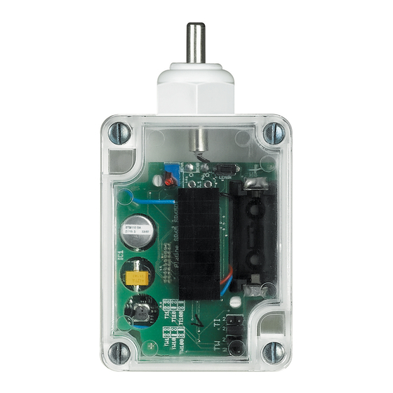
- Page 207 1 - Fresnel lens; CONFORMITY DECLARATION 2 - LED: Two red flashes signal an alarm; only one flash indicates that the battery is Item 3440 meets the essential requirements of directive 1999/5/CE, as it complies with exhausted. the following standards: ETSI EN300 220-3 ETSI EN301 489-3 EN60950 EN50090-2-2 EN50090-2-3.
- Page 208 Radio IR detector 3440 Configuration Configurator socket Infrared radio detectors require assigning of the zone they belong to, of the progressive sensor number within the zone, setting of the detection mode and the allocation of an auxiliary prealarm channel. WARNING: the configuration operations must be performed with the battery disconnected.
- Page 209 Radio glass-breaking detector 3442 Description This sensor protects doors and windows and generates an alarm signal in case of unwanted opening. The device consists of two elements: - a magnet, to be installed on the window /door, with corresponding bracket/spacer; Magnet Radio transmitter - a battery powered radio transmitter with NC contact to be installed on the window/door...
- Page 210 Radio glass-breaking detector 3442 Configuration The device requires allocation of the zone it belongs to, the progressive number of the sensors within the same zone, and the setting of the detection mode, as well as the possible allocation of an auxiliary prealarm channel. WARNING: the configuration operations must be performed with the battery disconnected.
- Page 211 Radio glass-breaking detector 3442 Configuration Pairing magnetic contacts Cancelling magnetic contacts 1. Switch the system to “maintenance” mode. 1. Switch the system to maintenance mode. 2. Press the programming pushbutton of the radio receiver for five seconds, until the red 2.
- Page 212 Radio glass-breaking detector 3444 Description This device generates an alarm signal when the sensor detects the vibrations cause by the breaking of door or window glass. It consists of two elements: - a vibration sensor, to be installed on the glass of the door or window to protect; - a battery powered radio transmitter, to be installed on the frame;...
- Page 213 Radio glass-breaking detector 3444 Configuration The device requires allocation of the zone it belongs to, the progressive number of the sensors within the same zone, and the setting of the detection mode, as well as the possible allocation of an auxiliary prealarm channel. WARNING: The configuration operations must be performed with the battery disconnected This configurator assigns the number of the appropriate zone to the detector.
- Page 214 Radio glass-breaking detector 3444 Configuration Pairing detectors Cancelling detectors 1. Switch the system to “maintenance” mode. 1. Switch the system to maintenance mode. 2. Press the programming pushbutton of the radio receiver for five seconds, until the 2. Remove the power supply from the radio receiver. red LED comes on.
- Page 215 Radio rolling shutter opening detector 3445 Description This device is the radio version of the wired detector, item 3514. It generates an alarm if anyone attempts to open a rolling shutter. It consists of two elements: - a coil guide type rope detector to be fitted to the rolling shutter; - a battery powered radio transmitter to be installed inside the box of the rolling shutter or on the frame of the window to be protected.
- Page 216 Radio rolling shutter opening detector 3445 Configuration The device requires allocation of the zone it belongs to, the progressive number of the sensors within the same zone, and the setting of the detection mode, as well as the possible allocation of an auxiliary prealarm channel. WARNING: The configuration operations must be performed with the battery disconnected This configurator assigns the number of the appropriate zone to the detector.
- Page 217 Radio rolling shutter opening detector 3445 Configuration Pairing detectors Cancelling detectors 1. Switch the system to “maintenance” mode. 1. Switch the system to maintenance mode. 2. Press the programming pushbutton of the radio receiver for five seconds, until the red 2.
- Page 218 Radio remote control for teleassistance 3448 Description Radio device with three pushbuttons, for sending remote assistance requests. Pressing the larger pushbutton a radio signal is sent, which is transferred on the BUS of the Burglar-alarm system through the radio receiver item HC/HD/HS/L/N/NT4618. The two round pushbuttons are used to configure the device and for resetting (silencing) the current alarm.
- Page 219 Radio remote control for teleassistance 3448 Battery replacement MQ00051-c-EN 21/10/2013...
- Page 220 Relay actuator 3479 Description This device allows to repeat various types of alarms by means of a relay voltage-free contacts, depending on its configuration. It can be activated by a technical alarm interface, or by another signal through the auxiliary channel (AUX). Normally used for the control of gas/water safety solenoid valves, or third party devices (telephone diallers, optical notifications, etc.).
- Page 221 Relay actuator 3479 “Auxiliary” operating mode Configurators Description It activates by... It resets by... none Signalling with memory of the activation of any auxiliary Any AUX device of the system Pressure of the needle key on any technical alarm channel of the system. Typical example: signalling with interface with AUX configurator from 1 to 9 memory of any technical alarm.
- Page 222 Contact interface 3480 Description This interface is used to connect 2 independent contact lines that can be balanced by means of a resistance, and which tripping can be delayed, as well as one tampering protection line. It can be used to achieve centralisation of all interfaces inside junction boxes.
- Page 223 Contact interface 3480 Configuration Managing alarms/system arming/auxiliary channel generation management In this mode, two independent contact lines can be connected to the interface. The corresponding addresses must be specified in positions Z1, N1, and Z2, N2. The configurator in position MOD1 and MOD2 specifies the type of contact for the generation of the alarm, as per the following table: Configurator Sensor connected...
- Page 224 Contact interface 3480 Energy saving management with Temperature control - Use of a burglar-alarm system integrated with the Temperature control system: in this case, the contact interface is connected to the burglar-alarm system If the contact interface is used in conjunction with the temperature control system to optimise energy saving, two different types of configurations will be possible: BUS only, and communicates with the temperature control system BUS through the F422 interface.
- Page 225 Contact interface 3480 Flooding alarm management N. O. pushbutton Tamper line Alarm Reset Probe item 3482 MQ00045-d-EN 28/04/2014...
- Page 226 12 v contact interface 3480V12 Description This interface gives the possibility of connecting the alarm system to a sensor line (that can be balanced with resistance, and/or which intervention can be delayed) requiring 12 V power supply. Produced in the basic modular version, the device can be used when centralizing all the interfaces in junction boxes.
- Page 227 12 v contact interface 3480V12 Configuration Specific mode for connection to wired rolling shutter sensors Configurator Sensor connected Configurator Sensor connected Pulses (*) none NC contact NC contact - balanced Rolling shutter rope sensor - 12 (approx 20 cm) NC contact - delayed * delayed* NC contact - delayed * - balanced Rolling shutter rope sensor -...
- Page 228 12 v contact interface 3480V12 Connection with IR 3518 - 3518/50 - 3518/150 - 3519 barriers 13,8 13,8 ALL0 ALL1 Reset JP10 COM T COM C If the max absorption of the system allows it, it will be possible to directly connect the barrier to one interface only. WARNING: use a 30 m max twisted, unshielded cable.
- Page 229 12 v contact interface 3480V12 Installation The maximum length of the interface connection line depends on the absorption of the connected loads, as for the following table Siren Siren 4072L 4072A Power supply Power supply E46ADCN E47ADCN Interface Interface Absorption of the loads connected to the interfaces Maximum distance 50 mA 175 (*)
- Page 230 Technical alarm interface 3481 Description The technical alarm interface is used to receive signals from the outside (normally analogue signals, like the closing/opening of a contact), converting them into digital information for the BUS. This information gives the possibility of differentiating between alarm notifications, like the activation of the siren, or the telephone dialler, or the closure of the gas/water solenoid valve.
- Page 231 Technical alarm interface 3481 Activation from the technical alarm interface Configurators Relay opertating mode (description) Technical alarm with NC contact and activation of the auxiliary channel none Internal siren (MOD 0 or 2) sounds intermittently until one of the following events occurs: a) there is no longer an alarm;...
- Page 232 Alarm radio remote control 348220 348220 Description Radio wave control device recommended for all those installations where an exposed control device is not desired. It can also used with the video door entry system, to control accesses. The remote control must be used with the radio receiver item HC/HD/HS/L/N/NT4618. Technical data - Power supply: 3 V lithium battery - type CR2032...
- Page 233 Alarm radio remote control 348220 348220 Battery replacement MQ00050-c-EN 28/04/2014...
- Page 234 Advanced central unit with telephone communicator 573935 (White) 067520 573934 (Magnesium) 3485 Description The central unit has the function of supervising the burglar-alarm system, enabling the management of the zone sensors independent from one another. It is possible to save up to 16 activation scenarios and use them based on actual the needs. It’...
- Page 235 Advanced central unit with telephone communicator 573935 (White) 067520 573934 (Magnesium) 3485 Legend 1 - Battery housing; 2 - Tamper line (see note); 3 - T1 local tamper; 4 - Reset key; 5 - Serial connector for PC programming; 6 - Burglar alarm BUS; 7 - ON/OFF slide switch;...
- Page 236 Advanced central unit with telephone communicator 573935 (White) 067520 573934 (Magnesium) 3485 Wiring diagram It is good practice to protect the system from lightning by using surge protective devices, connect the corresponding earth clamp with the “earth” reference of the SPD discharger SPD, belonging to class II, as per the diagram shown.
- Page 237 Base central unit 3485B Description The central unit has the function of supervising the burglar-alarm system, enabling the management of the zone sensors independent from one another. It is possible to save up to 4 activation scenarios and use them based on actual needs. The device can manage up to 10 automations split as follows: - 1 actuated using an internal relay and coupled with intrusion events, technical alarms, or system status;...
- Page 238 Base central unit 3485B Legend 1 - Battery housing; 2 - Local contact; 3 - Tamper line (see note); 4 - T1 local tamper; 5 - Reset key; 6 - Firmware update serial connector; 7 - Burglar alarm BUS; 8 - ON/OFF slide switch; 9 - Relay for automation in case of alarm.
- Page 239 Standard burglar-alarm central unit with telephone communicator 3485STD Description The central unit has the function of supervising the burglar-alarm system, enabling the management of the zone sensors independent from one another. The device has two rear terminals for connecting 2 separate contact lines. It is possible to save up to 16 activation scenarios and use them based on actual the needs.
- Page 240 Standard burglar-alarm central unit with telephone communicator 3485STD Legend 1 - Battery housing; 2 - Tamper line (see note); 3 - T1 local tamper; 4 - Reset key; 5 - Serial connector for PC programming; 6 - Burglar alarm BUS; 7 - ON/OFF slide switch;...
- Page 241 Standard burglar-alarm central unit with telephone communicator 3485STD Wiring diagram It is good practice to protect the system from lightning by using surge protective devices, connect the corresponding earth clamp with the “earth” reference of the SPD discharger SPD, belonging to class II, as per the diagram shown. installed in the apartment distribution board (see diagram).
- Page 242 Advanced central unit with telephone communicator 3486 Description The central unit has the function of supervising the burglar-alarm system, enabling the management of the zone sensors independent from one another. It is possible to save up to 16 activation scenarios and use them based on actual the needs. It’ s fitted with built-in telephone communicator for sending a telephone message in case of alarm, or to check the status of the system when away from home, using a fixed or mobile phone.
- Page 243 Advanced central unit with telephone communicator 3486 Legend 1 - ON/OFF slide switch; 2 - Telephone line OUT; 3 - Telephone line IN; 4 - Reset key; 5 - T1 local tamper; 6 - Tamper line (see note); 7 - Burglar alarm BUS; 8 - MY HOME sound system BUS;...
- Page 244 Advanced central unit with telephone communicator 3486 Wiring diagram It is good practice to protect the system from lightning by using surge protective devices, connect the corresponding earth clamp with the “earth” reference of the SPD discharger SPD, belonging to class II, as per the diagram shown. installed in the apartment distribution board (see diagram).
- Page 245 GSM/PSTN gateway 3489GSM Description front view This device, thanks to the GSM telephone network, enables using the functions of the PSTN telephone communicator, which equips the burglar-alarm central units, even in places where the analog telephone network is not available or it is not cost-effective to activate it.
- Page 246 GSM/PSTN gateway 3489GSM Wiring diagram GSM antenna RJ11 3489GSM gateway PRI: 220 – 240 V~ 185 – 175 mA 50/60 Hz SCS: 27 Vdc 600 mA 3485STD burglar-alarm central unit PSTN line telephone devices Magnetic contacts line Burglar alarm BUS Warning: It is recommended to use only one RJ11 jack for the 3489GSM gateway to ensure calling in the event of an alarm.
- Page 247 Magnetic contacts 3510M 043100 043101 043108 3510 3510PB 3511 3512 3513 Description Magnet Contact Magnetic sensors are normally installed on the top side of windows or doors, opposite Magnet to the hinges, so that even with small forced openings, the distance created between the two components (magnet and reed contact) will be enough to cause an alarm.
- Page 248 Magnetic contacts 3510M 043100 043101 043108 3510 3510PB 3511 3512 3513 Dimensional data Magnet 3511 Reed contact enclosure 3513 3510 3510PB 3510M Maximum distances from the magnet and the contact Steel door Other doors 3512 MQ00041-c-EN 21/10/2013...
- Page 249 Rolling shutter detector 3514 Description This device can protect rolling shutters, or similar winding devices, and is made up of a reel-type cable detector to be positioned in the shutter box. The end of the cable, which can be extended up to 3.1 metres, is fastened to the base of the rolling shutter.
- Page 250 Glass-breaking detector 3516 Description This glass breaking detector is positioned on the window to be protected using the double-sided adhesive tape supplied. The break, or even a strong shock against the glass, causes the emission of a noise with characteristic frequency which the piezoelectric detector captures.
- Page 251 IR barriers for windows 3518 3518/150 3519 3518/50 Description The device consists of 2 columns, one operating as a TransmiTTer (TX), and the other as a receiver (rX). Both have a microprocessor for the management of the alarm and the synchronisation of the infrared beams. The table that follows shows the alarm tripping times based on the rays broken: Or: alarm with at least one ray broken (maximum sensitivity) anD: alarm with at least two rays broken (minimum sensitivity).
- Page 252 IR barriers for windows 3518 3518/150 3519 3518/50 Configuration The barriers are sold configured for operation in “anD” mode, with tripping time: 200ms. To change the mode use the internal microswitch as shown in the following table: OR 100ms OR 100ms OR 200ms OR 200ms OR 100ms...
- Page 253 IR barriers for windows 3518 3518/150 3519 3518/50 Wiring diagram Use of barriers with gateway 3480 or F482 E47/12 Power supply unit in addition to the one already in the burglar-alarm system. Used to power the barriers. TO Be cOnnecTeD TO THe BUs only to have the eXHaUsTeD BaTTerY indication for the central unit with a display.
- Page 254 Alarm IR remote control 4050 Description This easy to use IR remote control enables performing all the system arming and disarming operations, and to confirm the settings. It’s coded automatically by the control unit and has 4,000,000 code combinations. The specific programming procedure makes it impossible to detect the code, thus assuring full safety.
- Page 255 Outdoor siren 4072L 4072A Description These sirens have been designed so that they can be installed easily, are tamper resistant and withstand atmospheric agents. A tamper screw protects the sirens against pulling off/opening; when installing make sure that the tamper screw is correctly positioned. Outdoor siren item 4072L If there is a power cut the battery inside the siren gives the whole system a minimum life of 24 hours (as required by standard CEI 79-2).
- Page 256 Outdoor siren 4072L 4072A Configuration Control card internal view The external siren requires configuration of the progressive number. This is done by means of the jumper (1) of the internal control card. If the system has 2 external sirens the jumper (1) of the second siren must be cut. Internal siren card - connections Power supply-BUS twisted pair- (WHITE CABLE) battery:...
- Page 257 Alarm power supply 230 V E47ADCN Description The power supply must be used to power the burglar-alarm system. It supplies continuous 27 Vdc low voltage with a maximum current of 1 A, and is electronically protected (without fuse) against short circuit and overload. It’...
- Page 258 12 V output power supply E47/12 Description Device for the power supply of 12 V devices (e.g. IR barriers), designed for connection to a 12 V - 6.5 - 24 Ah back-up battery. The power supply can be installed in flush mounted switchboards item F115/8A, or in suitable electric switchboards, with opening protected using the appropriate anti-tampering device L4630.
- Page 259 Relay actuator F481 Description This device allows to repeat various types of alarms by means of a relay voltage-free con- tacts, depending on its configuration. It can be activated by a technical alarm interface, or by another signal through the auxi- liary channel (AUX).
- Page 260 Relay actuator F481 “Auxiliary” operating mode Configurators Description It activates by... It resets by... none Signalling with memory of the activation of any auxiliary Any AUX device of the system Pressure of the needle key on any technical alarm channel of the system. Typical example: signalling with memory interface with AUX configurator from 1 to 9 of any technical alarm.
- Page 261 Contact interface F482 Description These interfaces are used for connecting 2 independent contact lines - which can be balanced with a resistance, delayed on operation - and a protection Tamper line. Made in the modular version with 2 DIN modules these devices can be used in case it is necessary to centralise all interfaces in a board or in junction boxes.
- Page 262 Contact interface F482 Configuration MOD1 and MOD2 Specific mode for connection to wired rolling shutter sensors A configurator is connected to this position for selecting the operating mode of the Configurator Sensor connected Pulses (*) interface according to the type of contact or detector connected to the two lines. It Flush detector for rolling shutters 12 (about 20 cm) is possible to have balanced and unbalanced protection lines with the possibility to...
- Page 263 12 V contact interface F482V12 Description This interface gives the possibility of connecting the alarm system to two sensor lines (that can be balanced with resistance, and/or which intervention can be delayed) requi- ring 12 V power supply. Produced in the DIN modular version, the device can be used for centralizing all the inter- faces inside a cabinet.
- Page 264 12 V contact interface F482V12 Configuration MOD1 and MOD2 Specific mode for connection to wired rolling shutter sensors In this position a configurator is inserted for selecting the operating mode of the interface Configurator Sensor connected Pulses (**) according to the type of contact or detector connected to the two lines. Rolling shutter rope sensor - 12 (approx 20 cm) It will be possible to create both balanced and non balanced protection lines, with the...
- Page 265 12 V contact interface F482V12 Connection with IR 3518 - 3518/50 - 3518/150 - 3519 barriers 13,8 13,8 ALL0 ALL1 Reset JP10 If the max absorption of the system allows it, it will be possible to directly connect the barrier to the interface only. NOTE: If Z1 and N1 are configured, while leaving sockets Z2 and N2 empty, contact C2 will operate as a tamper line.
- Page 266 Technical alarm interface F483 Description The technical alarm interface is used to receive signals from the outside (normally analogue signals, like the closing/opening of a contact), converting them into digital information for the BUS. This information gives the possibility of differentiating between alarm notifications, like the activation of the siren, or the telephone dialler, or the closure of the gas/water solenoid valve.
- Page 267 Technical alarm interface F483 Activation from the technical alarm interface Configurators Relay opertating mode (description) none Technical alarm with NC contact and activation of the auxiliary channel Internal siren (MOD 0 or 2) sounds intermittently until one of the following events occurs: a) there is no longer an alarm;...
- Page 268 Signalling interface F80CMD Description Item F80CMD is a signalling and control interface for the associated device, for example the Stop&Go device item F80/SG. It consists of two signalling relays, two contacts for the connection of two pushbuttons, and one mode selector. Technical data - Power supply: from the associated device...
- Page 269 Signalling interface F80CMD Wiring diagram 1 - Connection for use with Stop&Go device, item F80/SG; 2 - Connection for use with Stop&Go device, item F80/SG and alarm event signalling through the burglar-alarm system. ASSOCIATED ASSOCIATED DEVICE DEVICE Burglar alarm BUS Control interface Aux channel interface...
-
Page 270: Hc4070
Indoor siren 573984 067515 HD4070 N4070 HC4070 HS4070 NT4070 Description This siren is fitted with battery (item 3507/6); up to a maximum of 3 indoor sirens can be installed inside the protected area. It can be installed in flush mounted boxes. The indoor siren can be programmed for signalling intrusion alarms through a continuous sound (frequency 1880Hz) and/or auxiliary alarms through a modulated sound. -
Page 271: Hc4601
Base central unit L4601 N4601 NT4601 HD4601 HC4601 HS4601 Description The central unit has the function of supervising the burglar-alarm system, enabling the management of the zone sensors independent from one another. It is possible to save up to 16 activation scenarios and use them based on actual the needs. - Page 272 Base central unit L4601 N4601 NT4601 HD4601 HC4601 HS4601 Legend 1 - Serial connector for the update of the firmware using a PC; 2 - Reset key; 3 - Local contact; PROG 4 - ON/OFF slide switch; 5 - Burglar alarm BUS; RESET 6 - Relay for automation in case of alarm;...
-
Page 273: Am5786
Keypad activator 5739 44 (White) 67506 HD4606 L4606 NT4606 5739 45 (Magnesium) HC4606 HS4606 N4606 AM5786 Description This device arms or disarms the system by keying a secret code previously stored in burglar- alarm systems central units with display, or in three module flush mounted central units. By pressing two pushbuttons (”o¬”... -
Page 274: Am5787
Transponder reader 067508 HC4607 HD4607 L4607 NT4607 573948 573949 HS4607 N4607 AM5787 Description The transponder reader is a device which activates when the Transponder badge (3530S or 3540) is in its immediate vicinity (1-2 cm). The signal generated by the approach of the badge is then transferred to the bus (BUS cable item L4669S). - Page 275 Transponder reader N° 067508 HC4607 HD4607 L4607 NT4607 573948 573949 N° HS4607 N4607 AM5787 Configuration Night function: when the system is disconnected, it is possible to activate the zones up to the numeric value of the configurator in AUX position. This function can be enabled with configurator 7 in MOD position if central units with a display are used or with configurator 8 if flush mounted central units item L/N/NT4600/4 are used.
- Page 276 Transponder reader 067508 HC4607 HD4607 L4607 NT4607 573948 573949 HS4607 N4607 AM5787 Configuration F420 AUTOMATION mode – SCENARIO MANAGEMENT: It coincides with the room of the scenario module item F420 where the actuation is performed – from 0 to 9 – (reference socket A on the scenario module). N°...
- Page 277 Transponder reader 067508 HC4607 HD4607 L4607 NT4607 573948 573949 HS4607 N4607 AM5787 Configuration 3479/F481 AUTOMATION mode – AUXILIARY CONTROL: This mode can be obtained by connecting the AUX configurator to MOD. This will generate a 1 sec. ON/OFF control on the assigned auxiliary channel. The difference when compared with the auxiliary function generated with the reader connected to the burglar-alarm N°...
- Page 278 1-4 zone transponder divider HD4607/4 N4607/4 NT4607/4 HS4607/4 HC4607/4 L4607/4 AM5787/4 Description This device is used to arm, disarm, and separate the zones of the system by placing a transponder badge (item 3530S and item 3540 previously stored in the central unit) in front of the zone transponder badge receiver.
- Page 279 1-4 zone transponder divider HD4607/4 N4607/4 NT4607/4 HS4607/4 HC4607/4 L4607/4 AM5787/4 Configuration AUTOMATION mode – SCENARIO MANAGEMENT: This configurator with value 0-9 coincides with the A position of the scenario module. N° Clamp for burglar This configurator with value 1-9 coincides with the PL position of the scenario module. alarm BUS Assigns the operating mode.
-
Page 280: Hc4608
Display keypad 5739 46 (White) HC4608 L4608 N4608 067507 5739 47 (Magnesium) HD4608 HS4608 NT4608 Description Using the transponder key, or a secret code set on the central unit, this device with display and digital keypad can be used to arm/disarm the system and separate the zones with the same flexibility and using the same procedure as for burglar-alarm central unit with display, or three module flush mounted central units. - Page 281 Display keypad 5739 46 (White) HC4608 L4608 N4608 067507 5739 47 (Magnesium) HD4608 HS4608 NT4608 Configuration The activator with display must be configured by assigning a zone address (Z), indicating Selecting the central unit installed in the system the activator group it belongs to, and a progressive number (N) within the group. To configure it as belonging to the activators group, no value must be entered in Z.
-
Page 282: Am5790
Passive IR detector 5739 36 (White) 067511 HD4610 L4610 NT4610 5739 37 (Magnesium) HC4610 HS4610 N4610 AM5790 Description The passive infrared detector is a volumetric detector with fixed lens, sensitive to the movement of warm bodies. The volume of the protected zone is divided into 14 beams distributed on 3 levels. - Page 283 Passive IR detector 5739 36 (White) 067511 HD4610 L4610 NT4610 5739 37 (Magnesium) HC4610 HS4610 N4610 AM5790 Configuration Infrared ray detectors require assignment of the appropriate zones and the progressive number of the sensors in the zone, setting of the detection mode and possibly N°...
- Page 284 Passive IR detector 5739 36 (White) 067511 HD4610 L4610 NT4610 5739 37 (Magnesium) HC4610 HS4610 N4610 AM5790 Configuration AUTOMATION mode – TIMED CONTROL: Passive IR detectors can generate and send an ON timed control directly to one or more actuators. For this mode, configure in the Z and N positions of the detector the addresses A and PL of the actuator to control respectively.
-
Page 285: Am5791
Passive IR detector 573938 (White) 067502 HD4611 N4611 NT4611 573939 (Magnesium) HC4611 HS4611 L4611 AM5791 Description Horizontal adjustment The passive infrared detector is a volumetric detector with tilting lens, sensitive to the movement of warm bodies. The volume of the protected zone is divided into 14 beams 30°... - Page 286 Passive IR detector 573938 (White) 067502 HD4611 N4611 NT4611 573939 (Magnesium) HC4611 HS4611 L4611 AM5791 Configuration Infrared ray detectors require assignment of the appropriate zones and the progressive number of the sensors in the zone, setting of the detection mode and possibly N°...
- Page 287 Passive IR detector 573938 (White) 067502 HD4611 N4611 NT4611 573939 (Magnesium) HC4611 HS4611 L4611 AM5791 Configuration AUTOMATION mode – TIMED CONTROL: Passive IR detectors can generate and send an ON timed control directly to one or more actuators. For this mode, configure in the Z and N positions of the detector the addresses A and PL of the actuator to control respectively.
-
Page 288: Am5791B
Passive IR detector L4611B NT4611B 067512 N4611B AM5791B Description Horizontal adjustment These devices are the simplified version of sensors item L/N/NT4611, item 675 02 and 30° 30° item AM5791. They have a fixed level of sensitivity (6 metres). Also in this case, the passive infrared detector is a volumetric detector with tilting lens, sensitive to the movement of warm bodies. - Page 289 Passive IR detector L4611B NT4611B 067512 N4611B AM5791B Configuration They require that the zone they belong to and the progressive sensor number within the zone are assigned. They also require setting of the detection mode. N° This configurator assigns the number of the appropriate zone to the detector. Clamp for burglar Configurator 1 assigns zone 1 to the detector, configurator 2 assigns zone 2 and so on to alarm BUS...
-
Page 290: Hc4613
Double technology IR+MW detector 5739 40 (White) 067504 HS4613 HC4613 N4613 5739 41 (Magnesium) 067503 HD4613 L4613 NT4613 Description This device consists of two sensors: one infrared sensor (IR) to detect the presence of warm bodies, and one microwave (MW) sensor to detect moving bodies. The combination of these technologies guarantees greater immunity against false alarms. - Page 291 Double technology IR+MW detector 5739 40 (White) 067504 HS4613 HC4613 N4613 5739 41 (Magnesium) 067503 HD4613 L4613 NT4613 Configuration Double-technology detectors require assignment of the appropriate zones and the progressive number of the sensors in the zone, setting of the detection mode and If the AUX configurator has been installed in the MOD position, the 1 to 9 value of the possibly assignment of an auxiliary prealarm channel.
-
Page 292: Hc4618
Alarm radio receiver HC4618 HS4618 N4618 HD4618 L4618 NT4618 Description The radio receiver, fitted in the MY HOME burglar-alarm sYStem, allows the use of devices which transmit radio wave signals (volumetric sensors, perimeter sensors, technical alarm sensors, radio system remote control, radio remote control for remote assistance) inside the burglar-alarm system, transferring the radio signal on SCS cable (item L4669S). -
Page 293: Ha4619
Radio flooding detector HA4619 HB4619 L4619 Description This device generates an alarm signal when the contacts of the corresponding sensor make contact with water. The signal is then processed by the alarm central unit, which activates the siren and the Telephone communicator (if installed), for sending a telephone message. - Page 294 Radio flooding detector HA4619 HB4619 L4619 Configuration The device requires allocation of the zone it belongs to, the progressive number of the sensors within the same zone, and the setting of the detection mode, as well as the possible allocation of an auxiliary prealarm channel. WARNING: The configuration operations must be performed with the battery disconnected This configurator assigns the number of the appropriate zone to the detector.
-
Page 295: N4640
Passive IR detector N4640 N4640B Description The passive IR detector is of volumetric type and sensible to movement of warm bodies. The volume of the protected zone is divided into 14 beams distributed on 3 levels. The detector works in two different ways: instantaneous or with impulse calculation, in order to reduce the possibility of false alarms. - Page 296 Passive IR detector N4640 N4640B Configuration N4640 Infrared ray detectors require assignment of the appropriate zones and the progressive number of the sensors in the zone, setting of the detection mode and possibly N° assignment of an auxiliary prealarm channel. This configurator assigns the number of the appropriate zone to the detector.
- Page 297 Passive IR detector N4640 N4640B Configuration N4640 AUTOMATION mode – TIMed CONTrOl: Passive IR detectors can generate and send an ON timed control directly to one or more actuators. For this mode, configure in the Z and N positions of the detector the addresses A and PL of the actuator to control respectively.
- Page 298 Passive IR detector N4640 N4640B Configuration item N4640B This device is the model with preset sensor sensitivity level, item N4640 and it only performs burglar-alarm system functions as it does not manage auxiliary channels or AUTOMATION modes; it requires allocation of the zone it belongs to, the progressive N°...
-
Page 299: L4669S
BUS cable L4669S Description Technical data The red SCS-BUS cable has been purposely designed and produced for the installation of - Insulation voltage: 300/500 V burglar-alarm systems This cable is used for the distribution of the power supplies and - Can be buried: NO; the operating signals to all system devices. - Page 300 Technical sheets - Temperature control...
- Page 301 Radio outdoor temperature probe 3455 Description The outside temperature can be measured by means of this radio probe. The data is then sent through radio waves to the receiving interface, and to the temperature control system. 99-zone or 4-zone central units can simply display this data. The automations are reserved just to the 99-zone central unit and can activate controls on the basis of exceeding particular temperature thresholds set by means of the TiThermo software.
- Page 302 Radio outdoor temperature probe 3455 Temperature display 4-ZONE CENTRAL UNIT for outdoor temperature display PROBE for temperature INTERFACE for detection and transmission data reception 99-ZONE CENTRAL UNIT for outdoor temperature display Automation - threshold exceeded LED t < 3° C t >...
- Page 303 Radio outdoor temperature probe 3455 Automations - system with integration boiler RISCALDAMENTO integration boiler switching valve chiller 99-zone central unit interface actuator probe Setting the temperature update interval Jumper sockets The radio probe sends the “temperature” reading to the receiving interface at regular intervals that can be manually set using the jumpers, which must be connected to the T1 and T2 sockets.
- Page 304 Radio outdoor temperature probe 3455 HC/HS 4577 and L/N/NT4577 receiving interface configuration In order to use a receiving interface and radio probe, configuration must first be performed, followed by the programming procedure. Only the interface needs configuring. Up to 2 probes may be combined with each interface, therefore providing the system with two detection points for each interface.
- Page 305 Air conditioning units control IR emitter 3456 Description The air conditioning units control IR emitter is a device capable of controlling the air conditioning units of the air conditioning system by sending infrared controls. All the Bottom view controls are sent to the splitter using the Touch Screen, or Multimedia Touch Screen, of the MY HOME system.
- Page 306 Air conditioning units control IR emitter 3456 Wiring diagrams IR transmitter connected to the PC for the acquisition of the remote control using the dedicated software IR transmitter connected to the splitter and the BUS MQ00357-c-UK 05/06/2014...
- Page 307 99-zone central unit 5739 18 (White) 067456 5739 19 (Magnesium) 3550 Description This central unit can manage temperature control systems up to 99 zones, set the system and modify the system operating mode. It is more complete than the 4-zone flush mounted version;...
- Page 308 99-zone central unit 5739 18 (White) 067456 5739 19 (Magnesium) 3550 Graphic display Circulation pump In normal working conditions the Central unit display shows the following information In addition to controlling the zone valves, for some types of systems it will also be on the initial page: necessary to control one or more water circulation pumps.
- Page 309 99-zone central unit 5739 18 (White) 067456 5739 19 (Magnesium) 3550 System with two circulation pumps The system shown requires two circulation pumps that serve two different zone groups controlled by their own solenoid valves. The first group pump is managed by a dedicated actuator configured in zone 00 with progressive number equal to 1 (N=1).
- Page 310 99-zone central unit 5739 18 (White) 067456 5739 19 (Magnesium) 3550 TiThermo software - customise the configuration parameters and the operating programs of the central unit TiThermo is the tool used for creating or changing, through a simple and logic graphic (e.g.
- Page 311 Actuator 2 relays F430/2 F430/2 Description By means of internal relays, this device executes the controls received from the central unit or the probe. It is needed to control loads such as motorised valves, pumps and electric radiators. It has two independent relays which can be used to control two distinct loads with ON/OFF function and to control a single load with open/close function.
- Page 312 Actuator 2 relays F430/2 F430/2 Configurator summary table: Socket Function Configurator zone address 0 – 9 Zone address - ON/OFF contact management - Open/Close contact management - 0 – 9 – OFF circulation pump mode - OFF zone progressive zone number - Open/Close contact management - 1 –...
- Page 313 Actuator 2 relays F430/2 F430/2 Example 2 Configuration and connection of the 2-relay actuator, for the control of two electric radiators within the same zone (zone 4). The progressive zone numbers are 1 and 2. Legend 1. actuator 2. electric radiators, zone 4 1 2 3 4 C1 C2 Actuator configuration...
- Page 314 Actuator 2 relays F430/2 F430/2 Example 4 Configuration and connection of the 2-relay actuator, for the control of two circulation pumps (zone 00). The progressive zone numbers are 1 and 2. Legend 1. actuator 2. boiler 3. refrigerator (chiller) 4. heating circulation pump HEATING 5.
- Page 315 Actuator 4 relays F430/4 Description By means of internal relays, this device executes the controls received from the central unit or the probe. It is needed to control loads such as 3-speed fan-coils, motorised valves, pumps and electric radiators. It has four relays,with independent control but common contacts, which can be used to control two distinct loads with ON/OFF function and to control a single load with open/ close function.
- Page 316 Actuator 4 relays F430/4 The ventilation speed is selected automatically by the temperature control function common based on the difference between the user set temperature and the room temperature. configurator This actuator cannot be used to control the system circulation pump (configurator in socket RL1 C1 contact RL1 zone 00), and to control separate loads belonging to the same zone.
- Page 317 Actuator 4 relays F430/4 Example 2 Configuration and connection of the 4 interlocking relays actuator for the control of two solenoid valves, with opening and closing control in zones 2 and 3. The progressive zone number is 2. Legend 1. actuator 2.
- Page 318 Actuator 4 relays F430/4 Example 4 Configuration and connection of two 4-relay actuators (one for the cooling, and one for The C1 contact of each actuator controls the corresponding solenoid valve, selected by the heating system), for the control of a 4-pipe, 3 speed fan-coil. For both actuators the the temperature control function based on the system setting (summer or winter).
- Page 319 F430R8 8 relay actuator Description This actuator can be used in temperature control systems to control different types of loads based on requirements. Thanks to the 8 relays it is fitted with, the actuator can control: • up to 8 On/off valves • up to 4 Open/Close or 3-point valves • up to 2 x 2-tube fan-coils with On/Off valves (4+4 relays) • 1 x 2-tube fan-coil with 3-point valves (5 relays)
- Page 320 8 relay actuator F430R8 F430R8 Wiring diagrams Example of connection of a 4-tube fan-coil with On/Off valves. OUT 3 OUT 2 OUT 1 OUT 5 OUT 4 230 Vac OUT 3 OUT 2 OUT 1 OUT 5 OUT 4 F430R8 MM00779-a- 30/09/2013...
- Page 321 F430R3V10 Fan-coil actuator with 0-10 V valves Description DIN modularity actuator to be used in temperature control systems for the control of 2-tube or 4-tube fan coils with 0-10 V valves It has with 3 relays for the managementof the fan-coil fan, and 2 x 0-10 V outputs for the control of the valves.
- Page 322 Fan-coil actuator with 0-10 V valves F430R3V10 Wiring diagrams Example of connection of a 4-tube fan-coil with 0-10 V valves. OUT 3 OUT 2 0 – 10 V OUT 1 230 Vac 0 – 10 V OUT 3 OUT 2 OUT 1 –...
- Page 323 F430V10 Actuator for 0-10 V valves Description DIN module actuator for the control of 0-10 V valves in temperature control systems It has two 0-10 V outputs, two control pushbuttons for manual opening/closing of each valve and the corresponding status LEDs. Technical data Power supply from SCS BUS: 18 –...
-
Page 324: Hc4577
Radio interface for outdoor temperature probes HD4577 HS4577 N4577 HC4577 L4577 NT4577 Description The radio interface is indispensable to receive the temperature data transmitted by the radio probe. Up to two probes can be associated with each interface thus giving the system two measuring points for each interface. -
Page 325: Ln4691
H4691 067459 Thermostat with display LN4691 64170 Description Thermostat with display for the control of the room temperature in temperature control systems. This device can be used both if a temperature control central unit is present or not present; when appropriately configured it can be used as: - MyHOME temperature control system probe;... - Page 326 Thermostat with display H4691 067459 LN4691 64170 COOL= Cooling load. For the configurations from 1 to 9 configure the corresponding Configuration actuator with N=2. In case of CEN configurator the actuator will be N=1. The thermostat can be configured: - Through physical configuration, by connecting the configurators to the appropriate Parameter/setting Physical housings on the back of the device.
-
Page 327: Am5872
Probe with selector 5739 22 (White) 067457 HC4692 L4692 NT4692 5739 23 (Magnesium) HD4692 HS4692 N4692 AM5872 Description The device can adjust the room temperature in both winter and summer, varying the settings locally with respect to those received from the central unit. The item has a knob for the local temperature selection (limited to ±... - Page 328 Probe with selector 5739 22 (White) 067457 HC4692 L4692 NT4692 5739 23 (Magnesium) HD4692 HS4692 N4692 AM5872 Configuration The probe must always be configured by connecting two configurators to the ZA and ZB probe itself. The actuators controlled by the probes must be configured with the same sockets, which identify the device address, and the number of the zone controlled by the zone address.
- Page 329 Probe with selector 5739 22 (White) 067457 HC4692 L4692 NT4692 5739 23 (Magnesium) HD4692 HS4692 N4692 AM5872 Circulation pump Pump switch-on delay In addition to controlling the zone valves, for some types of systems it will also be If necessary, it is also possible to set the circulation pump to activate after a certain time necessary to control one or more water circulation pumps.
-
Page 330: Hc4692Fan
Fan-coil probe with selector 067455 HD4692FAN HS4692FAN N4692FAN 5739 25 (Magnesium) 5739 24 (White) HC4692FAN L4692FAN NT4692FAN Description The device can adjust the room temperature in both winter and summer, varying the settings locally with respect to those received from the central unit. The item has a knob for the local temperature selection (limited to ±... - Page 331 Fan-coil probe with selector 067455 HD4692FAN HS4692FAN N4692FAN 5739 25 (Magnesium) 5739 24 (White) HC4692FAN L4692FAN NT4692FAN Configuration This probe has been specifically designed to manage 3-speed fan-coils and Climaveneta identifying the address of the device, and the number of the zone controlled by the fan-coils.
- Page 332 Fan-coil probe with selector 067455 HD4692FAN HS4692FAN N4692FAN 5739 25 (Magnesium) 5739 24 (White) HC4692FAN L4692FAN NT4692FAN Circulation pump When programming the operating mode of the circulation pumps is not necessary to In the following cases, pump control is not necessary: connect any special configurators: it will be sufficient to use the temperature central - in systems where the pump is always in operation (thanks to water recirculation unit.
-
Page 333: Hc4693
Probe without selector 067458 HD4693 HS4693 N4693 5739 21 (Magnesium) 5739 20 (White) HC4693 L4693 NT4693 Description The device can be used to control the room temperature, based on daily rhythms, both in winter and in summer. On the front of the device are a green and a yellow LED. The green led indicates that the device is working correctly. - Page 334 Probe without selector 067458 HD4693 HS4693 N4693 5739 21 (Magnesium) 5739 20 (White) HC4693 L4693 NT4693 Configuration The probe must always be configured by connecting two configurators to the ZA and ZB probe itself. The actuators controlled by the probes must be configured with the same sockets, which identify the device address, and the number of the zone controlled by the zone address.
- Page 335 Probe without selector 067458 HD4693 HS4693 N4693 5739 21 (Magnesium) 5739 20 (White) HC4693 L4693 NT4693 Circulation pump Pump switch-on delay In addition to controlling the zone valves, for some types of systems it will also be If necessary, it is also possible set the circulation pump to activate after a certain time necessary to control one or more water circulation pumps.
-
Page 336: Am5875
4-zone central unit HC4695 L4695 NT4695 HD4695 HS4695 N4695 AM5875 Description This central unit can manage MY HOME temperature control systems with up to 4 zones, with a maximum of 9 circulation pumps. It can control heating or cooling systems and can set the system and modify the system operating mode. - Page 337 4-zone central unit HC4695 L4695 NT4695 HD4695 HS4695 N4695 AM5875 Removable system The central unit is made up of a base for the connection to the system bus cable and a removable front cover with batteries. The system so formed lets the user perform the programming operations and replace the batteries easily.
- Page 338 4-zone central unit HC4695 L4695 NT4695 HD4695 HS4695 N4695 AM5875 Programming 4 zone central unit calibration The 4 zone central unit does not normally require calibration: however, in particular The central unit must be used to set the operating mode of the integrated probe fitted inside.
- Page 339 4-zone central unit HC4695 L4695 NT4695 HD4695 HS4695 N4695 AM5875 Circulation pump System with a circulation pump The system shown only has one circulation pump, that only supplies two zones, controlled In addition to controlling the zone valves, for some types of systems it will also be necessary to control one or more water circulation pumps.
- Page 340 4-zone central unit HC4695 L4695 NT4695 HD4695 HS4695 N4695 AM5875 System with two circulation pumps The system shown requires two circulation pumps that serve two different zone groups The second group is similar to the first one, but the actuator controlling the pump controlled by their own solenoid valves.
- Page 341 4-zone central unit HC4695 L4695 NT4695 HD4695 HS4695 N4695 AM5875 TiThermo Basic software TiThermo Basic is the tool used for creating or changing, through a simple and logic - manage the circulation pumps, selecting the type of function to be assigned (heating, graphic interface, the configuration to be sent to the temperature control system central cooling, heating+cooling, no function) and the tripping delays unit, defining and customising the parameters of the temperature control system and...
- Page 342 Technical sheets - Load control management and Consumption display...
- Page 343 Pulse counter interface 3522N Description Front view The device detects, counts and processes the information (water, gas, etc.) received from meters with pulse outputs, and makes it available to the SCS BUS. The processing and accounting functions are: - calculation of the instantaneous value (flow rate - unit/h): the distance between two consecutive pulses.
- Page 344 Pulse counter interface 3522N Physical configuration 1.1 MUL position 1.2 DIV position The configurator in the MUL position specifies the multiplication factor to be applied to The configurator in the DIV position specifies how many pulses must be measured by the single pulse, as specified in the following table: the interface to produce a valid effective pulse for energy accounting, as specified in the following table:...
- Page 345 Electricity meter with three inputs F520 Description Front view The SCS device measures currents and voltages of separate lines (up to 3), connecting at most three toroids to the appropriate inputs (one toroid, item 3523, supplied as standard). The meter processes and saves the following variables: - instantaneous power in W;...
- Page 346 Electricity meter with three inputs F520 Configuration If the device is installed in a My Home system it can be configured in two ways: The maximum number of addresses is 127. - PHYSICAL CONFIGURATION, inserting the configurators in position. WARNING: The A3-Ta configurator cannot be zero, unlike configurators A3-Tb and A3- - Configuration via MYHOME_Suite software package, downloadable from Tc, which can have a zero value (if the corresponding input is not managed).
- Page 347 Electricity meter with three inputs F520 Wiring diagrams Connection of the meter to the bus, the line, and the toroid 230 Vac MQ00358-c-EN 07/06/2014...
- Page 348 Load control central unit F521 Description Front view The central unit for load management is an SCS device that measures the power consumed by the electric system and controls the state of the Load Management system actuators, to prevent the risk of the electric meter tripping. The device can manage up to 63 actuators (electric loads) per phase.
- Page 349 Load control central unit F521 Configuration If the device is installed in a My Home system it can be configured in two ways: The load control central unit has a bay for five configurators, which define: - PHYSICAL CONFIGURATION, inserting the configurators in position. - A1/A2/A3 address of the central unit (A1 for hundreds, A2 for tens, A3 for units);...
- Page 350 Load control central unit F521 Load control actuators acquisition Once the installation stage has been completed, the central unit must acquire the turns green, and the central unit starts operating correctly. actuators on the bus; unless this operation is carried out, the device will continue The procedure for the acquisition is inhibited if the central unit is not installed correctly signalling lack of information (steady orange LED), and no load control function will be (voltage on the bus too low, or no 230V), or if an overload is present;...
- Page 351 Load control central unit F521 Wiring diagrams 230 Vac Load control central unit connection MQ00360-c-EN 09/06/2014...
- Page 352 Actuator 16A with current sensor F522 Description Front view The device is an actuator with 1 bistable relay sensor with zero crossing functionality, intended for the load control and/or automation functions. In load control mode: The actuator will be given a priority indicating the tripping order that will be followed by the F521 load control central unit (e.g.
- Page 353 Actuator 16A with current sensor F522 List of Functions The device performs the following functions: 1. LIGHT SWITCH 2. LOAD CONTROL ACTUATOR Configuration The device can be configured in two ways: - PHYSICAL CONFIGURATION, inserting the configurators in position. - Configuration via MYHOME_Suite software package, downloadable from www.homesystems-legrandgroup.com;...
- Page 354 Actuator 16A with current sensor F522 LED signals according to the status of the actuator in automation mode: Device status Load OFF GREEN Load ON ORANGE 2. Load control actuator 2.1 Load control management mode: In the P1 and P2 positions it will be necessary to indicate the priorities from 01 to 63, in PF the power factor (see table), the A, PL and M positions must be configured equal to zero.
- Page 355 Actuator 16A with current sensor F522 LED signals according to the status of the actuator in load control management mode: Device status Enabled ORANGE Enabled with consumption less than 50 W ORANGE flashing 900 ms ON/100 ms OFF on GREEN Forced ORANGE flashing 1s/1s on GREEN Disabled...
- Page 356 Actuator 16A with current sensor F522 Wiring diagrams WARNING: Cables carrying high currents installed Actuator connection: vertically near the actuator (< 5 cm) may cause false 230 Vac measurements of the integrated current sensor. In this case move the cables away and keep the phase and the neutral coupled.
- Page 357 Actuator 16A F523 F523 Description Front view The device is an actuator with 1 bistable relay with zero crossing functionality, intended for the load control management and/or automation functions. The actuator is capable, in an isolated manner, of assessing the frequency (50 Hz) and voltage (230 Vac) In load control mode: The actuator will be given a priority indicating the tripping order that will be followed by the...
- Page 358 Actuator 16A F523 F523 Configuration The device can be configured in two ways: For a list of the procedures and their meanings, please refer to the instructions in - PHYSICAL CONFIGURATION, inserting the configurators in position. this sheet and to the "Function Descriptions" help section in the - Configuration via MYHOME_Suite software package, downloadable from MYHOME_Suite software package.
- Page 359 Actuator 16A F523 LED signals according to the status of the actuator in automation mode: Device status LED status Load OFF GREEN Load ON ORANGE LED signals according to the status of the actuator in load control manage- ment mode: Device status LED status Enabled...
- Page 360 Actuator 16A F523 Wiring diagrams Actuator connection: NOtE: For loads with current draw greater than 16 A add a supporting relay between the ac- 230 Vac tuator and the load. LOAD MQ00362-d-EN 09/06/2014...
- Page 361 Energy Data Logger F524 Description Lower view Lower view The energy data logger is a device that can be used to: - Display on the PC or other device (e.g. Smartphone) consumption/production data, recalling the web pages using an Internet Browser: - Concentrate and save data consisting of 10 separate energy lines maximum.
-
Page 362: Hc4672N
2-module flush-mounted actuator 16A HC4672N HS4672N HD4672N L4672N N4672N NT4672N Description Front view The device is an actuator with 1 bistable relay sensor with local pushbutton for load forcing/local control for the Automation and/or Load control management functions. In load control mode: The actuator will be given a priority indicating the tripping order that will be followed by the F521 load control central unit (e.g. - Page 363 2-module flush-mounted actuator 16A HC4672N HS4672N HD4672N L4672N N4672N NT4672N Configuration The device can be configured in two ways: For a list of the procedures and their meanings, please refer to the instructions in - PHYSICAL CONFIGURATION, inserting the configurators in position. this sheet and to the "Function Descriptions"...
- Page 364 2-module flush-mounted actuator 16A HC4672N HS4672N HD4672N L4672N N4672N NT4672N LED signals according to the status of the actuator in automation mode: Device status Two-colour LED Red LED Load OFF GREEN Load ON ORANGE LED signals according to the status of the actuator in load control management mode: Device status Two-colour LED...
- Page 365 2-module flush-mounted actuator 16A HC4672N HS4672N HD4672N L4672N N4672N NT4672N Wiring diagrams Actuator connection: 230 Vac 230 Vac 230V LOAD BUS – SCS SCS – BUS NOtE: For loads with current draw greater than 16 A add a supporting relay between the actuator and the load. MQ00363-d-EN 09/06/2014...
-
Page 366: Hc4673
Load control panel HD4673 HS4673 N4673 067206 573985 HC4673 L4673 NT4673 067207 573991 Description Front panel with no Cover The load control panel is a device that enables displaying the status of the loads controlled by the load control central unit, item F521, and force their operation inde- pendently from the central unit itself. - Page 367 Load control panel HD4673 HS4673 N4673 067206 573985 HC4673 L4673 NT4673 067207 573991 Virtual and physical configuration Virtual configuration (MYHOME_Suite) Physical configuration Function Parameter / setting Priority 0-63 P1 - ab address of tens for the loads assigned to buttons “a” and “b”, values from 0 to 6.
- Page 368 Gateway GATEWAY Description This device represents the interface between the MY HOME Temperature control system and the Climaveneta IDRORELAX system. The item allows the passage of the controls produced by the bus system toward the fan-coil. It is necessary to consider one for each fan-coil, thus correctly scaling the bus system as regards absorption and configuration.
- Page 370 Technical sheets - Video door entry sytem...
- Page 371 TECHNICAL SHEETS A/V SCS/BUS cable (white) 336904 Description This cable is used for the distribution of the power supplies and the operating signals to all BUS system devices. The cable consists of a white external sheathing and two twisted flexible conductors with a section of 0.5 mm2, one brown and one brown/white.
- Page 372 TECHNICAL SHEETS Wall mounted LINEA 2000 METAL entrance panel 342991 - 342992 Description Wall mounted 2-wire pushbutton panel with Zamak front cover, colour camera, and night viewing white LED light. One and two-family version available. The camera can be swivelled by +/-15°, both horizontally and vertically. It provides the possibility of opening an electrical door lock connected directly to clamps S+ and S- (18 V 4 A impulsive, 250 mA holding current).
- Page 373 TECHNICAL SHEETS 342991 - 342992 T - door lock relay timing Configuration configurator number The device must be configured as follows: 0= No configurator P - entrance panel number The configurator in seat P of the speaker module assigns to it a recognition number 4 sec.
- Page 374 TECHNICAL SHEETS Flush mounted LINEA 2000 METAL entrance panel 343001 - 343002 Description Flush mounted 2-wire audio and video speaker module with Zamak front cover, colour camera and night viewing white LED light. One and two-family version available. The camera can be swivelled by +/-20°, both horizontally and vertically. It provides the possibility of opening an electrical door lock connected directly to clamps S+ and S- (18 V 4 A impulsive, 250 mA holding current).
- Page 375 TECHNICAL SHEETS 343001 - 343002 Configuration The device must be configured as follows: P - entrance panel number The configurator in seat P of the speaker module assigns to it a recognition number inside the system. The numbering of the entrance panels must always start from P=0. The entrance panel configured with P=0 must be a common (or main) entrance panel.
- Page 376 TECHNICAL SHEETS Polyx Memory Display 344163 Description Front view 2 WIRE wall mounted speaker phone video handset with audio and video memory. With 3.5” colour LCD display with PC customisable icons OSD navigation menu for the management of the following MY HOME applications: Video door entry system, temperature control, sound system, scenarios, burglar alarm.
- Page 377 TECHNICAL SHEETS 344163 Configuration Polyx Memory Display can be configured in two different modes: - Quick configuration (with physical configurator connection); - Advanced configuration (using the TiPolyxMemoryDisplay software supplied). The quick configuration enables the user to access the video door entry system function menu.
- Page 378 TECHNICAL SHEETS Inductive LOOP module 344165 Description 2 WIRE inductive LOOP module to be used with Polyx Memory Display 344163 video handset, to enable use by people wearing hearing aids (fitted with T selector). The device must be configured with the same address (N) of the corresponding video handset.
- Page 379 TECHNICAL SHEETS LIVINGLIGHT VIDEO DISPLAY 344400 - 344401 Description Front view 2-WIRE hands free video handsets for flush mounted installation or in FLATWALL column. 2.5” colour LCD display with PC customisable OSD navigation icon menu for the management of the following applications: video door entry system, temperature control, sound system, scenarios and anti-intrusion.
- Page 380 TECHNICAL SHEETS 344400 - 344401 Configuration The advanced PC configuration using the software (CD supplied), provides the user LIVINGLIGHT VIDEO DISPLAY can be configured in 2 different modes: with a higher degree of customisation, with the possibility to: - Fast configuration (through the connection of physical configurators) - Advanced configuration (using the TiLivingLightDisplay software supplied with - create flexible menus the product).
- Page 381 TECHNICAL SHEETS Audio POLYX 344082 Description 2 WIRE handsfree handset for wall mounted installation. It’s fitted with keys for: EP activation/cycling, door lock release, staircase light switching on and 4 programmable keys, which operating mode is set through the configuration. Specific audible and visual signals mean that it is also suitable for use by disabled people.
- Page 382 TECHNICAL SHEETS 344082 Configurator in P key ( ) function Configuration Entrance panel audio activation N - handset number (configured with P=0-9) Assigns to each handset an identification number within the system. The handsets must be configured in progressive order. Handsets with parallel connection (max 3 are allowed inside apartments without item 346850) must be configured using the same Configurator in P function...
- Page 383 TECHNICAL SHEETS 344082 Configuration Below are the various operating modes that can be assigned to the 4 programmable keys: MODE FUNCTION NOTES MOD = Intercom on itself, it sends the call to all handsets with the same address. EP activation (configured with P+1), directly, without call, or activation of the actuator, item 346200 (configured with P+1 and MOD=9) EP door lock release (configured with P+1), directly, without call, or activation of the actuator, item 346200 (configured with P+1 and MOD=5), or activation of door...
- Page 384 TECHNICAL SHEETS 344082 MODE FUNCTION NOTES MOD = Intercom inside the apartment, in systems with apartment interface item 346850, or intercom among apartments without apartment interface. Intercom inside the apartment, in systems with apartment interface item 346850, or intercom among apartments without apartment interface. Intercom inside the apartment, in systems with apartment interface item 346850, or intercom among apartments without apartment interface.
- Page 385 TECHNICAL SHEETS 344082 MODE FUNCTION NOTES Activation of the scenario saved in the scenario module (SCENARIO 1) MOD = Activation of the scenario saved in the scenario module (SCENARIO 2) EP door lock release (configured with P+1), directly, without call, or activation of the actuator, item 346200 (configured with P+1 and MOD=5), or activation of door lock actuators 346230-346260 (configured with P+1) EP door lock release (configured with P+2), directly, without call, or activation of...
- Page 386 TECHNICAL SHEETS 344082 MODE FUNCTION NOTES MOD = Intercom between apartments, in systems with apartment interface, item 346850 Intercom between apartments, in systems with apartment interface, item 346850 Intercom between apartments, in systems with apartment interface, item 346850 Intercom between apartments, in systems with apartment interface, item 346850 Activation of the scenario saved in the scenario module (SCENARIO 1) MOD =...
- Page 387 TECHNICAL SHEETS 344082 Configuration 20 = B 40 = C 60 = D 80 = E A Configuration selected for the operation of the keys (see previous pages) B Configuration selected for the operation of the keys + OFFICE function C Configuration selected for the operation of the keys + PAGING function D Configuration selected for the operation of the keys + HANDSFREE function (Can be activated only on a single device for each unit system) E Configuration selected for the operation of the keys, OFFICE and PAGING function...
- Page 388 TECHNICAL SHEETS 344082 OFFICE FUNCTION DETAIL With the function active, when a call is received from the entrance panel, the video handset rings and the associated door lock is automatically released, without the need for pressing the door lock release key on the handset.
- Page 389 TECHNICAL SHEETS 344082 DOOR STATUS function PUSH TO TALK function This function notifies the status of the door lock. If open, the “door lock LED” flashes, if If the entrance panel is in a particularly noisy position, during the conversation it will closed, the LED stays off.
- Page 390 TECHNICAL SHEETS 344082 Programming of bells Bell selection from MAIN ENTRANCE PANEL (S=0) EXIT EXIT >3s >3s EXIT EXIT EXIT >3s >3s >3s EXIT EXIT >3s EXIT >3s EXIT >3s EXIT EXIT >3s >3s >3s EXIT EXIT EXIT EXIT >3s >3s >3s >3s...
- Page 391 TECHNICAL SHEETS CLASSE 100 A12B Handsfree internal unit 344252 Description Front view 2 WIRE audio handsfree internal unit for wall mounted installation. Keys available: auto-switching on / cycling, door lock release, staircase lights control, and handsfree connection. Depending on the configurator connected to (M), the same keys will perform different functions (see the specific configuration section).
- Page 392 TECHNICAL SHEETS 344252 Configuration The device must be only physically configured. N - handset number The configurators connected to the N sockets of the device assign an identification number within the system to each handsfree internal unit. The handsets must be configured in progressive order.
- Page 393 TECHNICAL SHEETS 344252 Configuration MODE FUNCTION M = 2 (with key tone active) Internal intercom. It sends the call to all the handsets with the same address. Audio enabling / disabling following a call. Direct EP door lock activation (EP configured with the same P), or activation of the EP door lock upon connection. Staircase light switching on.
- Page 394 TECHNICAL SHEETS 344252 Programming of bells LED notifications The handsfree internal unit offers the possibility to select among 16 types of Door lock status and/or door status red LED notifications: bells with programmed ringtones, which can be freely associated to the following type of calls: LED ON steady = door lock pushbutton pressed;...
- Page 395 TECHNICAL SHEETS Iryde Touch Phone 345020 - 345021 Description Front view 2 wire telephone and video handset for wall mounted installation (with optional bracket, item 345024) or table-top version (with optional support, item 345023). It has a 16/9, 4.3” LCD colour touch screen display with icon navigation menu, which can be customised using a PC for the management of the functions: - telephone;...
- Page 396 TECHNICAL SHEETS 345020 - 345021 Dimensional Data Configuration Iryde Touch Phone can be configured in two different modes: - Basic configuration: when switched on for the first time, the product asks the user to select the language. After this has been done, if no physical configurators are present, the device displays a main page showing the video door entry system icon (inside which, standard door entry system commands can be found: camera, door lock release, intercom, automatic cycling), the telephone icon, and the settings icon.
- Page 397 TECHNICAL SHEETS 345020 - 345021 - Address book: using the telephone menu, the address book can be used for the following functions: add a contact, delete a contact, change a contact, select and call a contact, customise a contact by associating a photo to the number (using the software), management of several numbers (max 3) for each contact.
- Page 398 TECHNICAL SHEETS 345020 - 345021 Wiring diagrams One-family system without PABX Telephone line PLT1 PLT1 345020 345020 PSTN PSTN PSTN PSTN 345020 345020 346000 346830 Entrance panel BUS 2 1 230 Vac ITEM DESCRIPTION QuANTITy PLT1 Protection of telephone line 345020 Iryde Touch Phone 346830...
- Page 399 TECHNICAL SHEETS 345020 - 345021 230 Vac One-family system with PABX 346020 346020 PRI: 220 – 240 V~ 175 – 165 mA 47/63 Hz SCS: 27 Vdc 600 mA PSTN 345020* PSTN PSTN 345020* 345020* PSTN PSTN 345020* 345020* Telephone line 110-240 Vac 346830...
- Page 400 TECHNICAL SHEETS 230 V A/V SCS/BUS power supply 346000 Description 2 wire system power supply unit, to be used in audio systems together with 2 wire speaker modules, or with the universal speaker unit, item 346991, for the installation of systems with up to 100 entrance panels (56 when item 346991 is used), as well as in video or mixed audio/video systems, when using video adapter item 346830, or the audio/video node item F441, or the multichannel matrix F441M.
- Page 401 TECHNICAL SHEETS Additional power supply 230 V 346020 Description 2 DIN module devices which allows to: - locally supply the single video door entry handsets and entrance panels. - supply some accessories of the Communication and MY HOME catalogues (ex: Web server, A/V server, scenario programmers, 2 WIRE/IP interface, switch 10/100, ADSL modem router, Hub-TV and SCS modulator).
- Page 402 TECHNICAL SHEETS Mini power supply 230 V 346030 Description 2 DIN module device for: - basic video door entry systems (e.g. apartment intercom) - mini SOUND SYSTEMS (absorption up to 600 mA). It is a double insulation safety device. The power supply is inside a module plastic rail enclosure, and its installation must be in accordance with the regulations of the country of use.
- Page 403 TECHNICAL SHEETS Actuator 346200 Description Relay actuator for digital systems. It allows to switch on lights, to open gate door locks, to control other devices and to repeat call on bell (badenia type). Technical data Power supply from SCS BUS: 18 – 27 Vdc Stand by absorption: 15 mA Max.
- Page 404 TECHNICAL SHEETS 346200 Configuration The device must be physically configured in terms of: MOD = Operating mode The configurator in MOD establishes the operating mode of the actuator (see following tables) M = number of the riser In systems with several risers, it identifies on which riser the actuation must be performed N/P = Handset/Entrance panel number It defines the association with the Handset or the EP address from which the actuation...
- Page 405 TECHNICAL SHEETS 346200 MOD = 3 - Sundry services from single handset - The actuator is enabled by pressing the light pushbutton of only one handset. Example - Customize the time through the configurator T. - Put in N/P the ten and the units of the handset that controls the relay 1 5 1 Unit Door lock control from the light key of the...
- Page 406 TECHNICAL SHEETS 346200 MOD = 9 - Sundry services (door lock/open the gate/staircase light) from PIVOT/SWING/POLYX handsets additional keys Example - Direct door lock opening with handset in pause. - Customize the time through the configurator T. - Insert in N/P the address that the actuator must take inside the system. The N/P value inserted in the actuator must be between P + 1 and P + 4 of the P Device control by pressing the key 2 of the 4 configurator P inserted in the handset which controls the service.
- Page 407 TECHNICAL SHEETS 346200 Wiring diagram BUS IN BUS OUT NC C NO 230V~ = 0,5 SELV 2-wire standard wiring diagram Bus PI Bus TK 346000 346200 346830 230V a.c. C NO...
- Page 408 TECHNICAL SHEETS Door lock actuator 346230 Description 2-wire system door lock actuator. It can be used to actuate an electrical door lock without the need for a local transformer, activated by a dedicated handset key. In systems with handsets with specific LED, it enables to perform the “LOCK STATUS” 2 PL S+ S- function when a CISA ELETTRIKA door lock is used.
- Page 409 TECHNICAL SHEETS 346230 Wiring diagram - 2-wire standard Wiring diagram - with auxiliary transformer BUS-SCS BUS-SCS 18 V - 4 A impulsivi 250 mA di mantenimento *A = pulsante apertura serratura 2 PL S+ S- 2 PL S+ S- 346230 346230 346000 346000...
- Page 410 TECHNICAL SHEETS Door lock relay 346250 Description Relay module for gate opening to be used only with audio/video SFERA New, SFERA ROBUR, SFERA Classic item 342560, LINEA 2000, LINEA 2000 METAL and MINISFERA entrance panels. NC NO S- S+ It allows to open door locks (NOT managed by BUS) by means of the above mentioned entrance panels (NOT fitted with relay).
- Page 411 TECHNICAL SHEETS Timed door lock actuator 346260 Description Timed door lock actuator for 2 WIRE system. It can be used for switching the lights on, opening gates, or manage electromagnetic door locks, timed door opening, and door status (with NC contact). The DOOR STATUS function can only be used with door entry systems and video door - TMP PL RC C NC...
- Page 412 TECHNICAL SHEETS 346260 Configuration The device must be physically configured in terms of: T J1 J2 P - Associated entrance panel number A B C A configurator like the one inserted in P of the entrance panel must be connected to this socket.
- Page 413 TECHNICAL SHEETS 346260 Connection example 18 V 4 A EP: P=1 - TMP PL RC C NC NO/S+ S- ART. 346260 TK BUS T= -5 +45°C IP 30 = Door lock pushbutton in the entrance-hall *S+ S- = 18V 4A impulsive 250mA holding current 346000 M R T J1 J2...
- Page 414 TECHNICAL SHEETS Video adapter 346830 Description 2 WIRES video adapter that must be used wih the power supply item 346000 in the installation of video systems (or audio/video combined), video door entry systems and sound systems. Allows the connection to its 3 BUS clamps. Hence it is possible to realize installations with 2 video entrance panels and 1 riser and installations with 1 video entrance panel and 2 risers.
- Page 415 TECHNICAL SHEETS Floor call interface 346833 Description Floor call interface which allows, by means of a traditional pushbutton, to make the following functions: - general floor call - addressed floor call - staircase light switching on - Door lock opening (with specific actuator) - associate the video image to the call to the floor WARNING: the maximum connection distance between the interface and the connected pushbuttons must not exceed 3 metres.
- Page 416 TECHNICAL SHEETS 346833 Note installative The MOD = 4 configuration mode enables associating the video image of a camera to the call to the floor generated by the off-door pushbutton. To use this function correctly, the following must be taken into account: - The involved handsets, the 346833 interface, and the camera must be physically connected on the same SCS BUS.
- Page 417 TECHNICAL SHEETS Floor shunt 346841 Description The floor distribution block can be used for video door entry systems with a star distribution of the wiring. The distribution block is in a plastic enclosure with much reduced dimensions for easier positioning (above all during the refurbishments) even with the installation inside flush ART.
- Page 418 Video door entry system 346850 Apartment interface Description Front view Interface to be used for the installation (inside the apartment/home) of a dedicated 2 WIRE system separated from the apartment complex riser. The system downstream the interface (inside the apartment/home) can include dedicated entrance panels and cameras, and if required can also be integrated with the MyHOME automation applications.
- Page 419 Apartment interface 346850 Configuration The device must be physically configured in terms of : Installation example N = device ID number The configurator assigns to the interface a unique handset number inside the system. M = Operating mode (M=3) - Standard factory configuration (M=4) - If one or more internal units with local power supply are installed inside the apartment/home, a configurator 4 must be connected to M.
- Page 420 TECHNICAL SHEETS System expansion interface 346851 Description Interface in DIN modular enclosure, used to increase the performance of the 2 WIRE system in one-family or apartment installations. It enables creating 2 WIRE risers with entrance panels at the bottom of the stairs, independent audio and video, as well as providing expansion for: regeneration of the video signal and extension of distances for a further 200 meters (cable item 336904 required), increase of the number of devices that can be connected to the BUS, and use of up to a maximum of 3 interface modules...
- Page 421 TECHNICAL SHEETS 346851 Configuration The device MUST BE configured with physical configurator connection to the appropriate sockets as follows: M = progressive number within the system The configurator connected to the M sockets (from 1 to 99) assigns an identification number within the system to the interface.
- Page 422 TECHNICAL SHEETS 346851 MOD = 5 (independent risers) This mode is used to create systems with 2 WIRE risers, with independent audio and video (39 risers maximum) - see the following example: The handsets connected to the single riser will be identified at the main entrance panel by the M configurator of 346851 x 100 + the N configurator of the single handset.
- Page 423 TECHNICAL SHEETS 346851 MOD = 6 (extended riser) MOD = 7 (extended riser expansion) These configuration modes offer the possibility of riser line expansion up to the logic When interface item 346850 is not used, this 100 handsets line limit will be further limit of 300 riser handsets (3 lines of 100 handsets each).
- Page 424 TECHNICAL SHEETS Coaxial - 2 WIRE interface 347400 Description Interface used for connecting the cameras with 12 Vdc power supply (max. absorption 150 mA) and coaxial video output (1 Vpp @ 75 ohm) to the 2-wire video BUS. The interface provides direct power supply to the camera. the device can be used as an interface for the separate camera;...
- Page 425 TECHNICAL SHEETS 347400 Configuration The device must be physically configured in terms of: P = camera address The configurator in seat P of the interface assigns to it a recognition number inside the system. The interface is considered as a video entrance panel, therefore it must be configured with a progressive number in relation to (P) of the entrance panel.
- Page 426 TECHNICAL SHEETS 347400 Configuration Example of configuration Interface Interface EP 1 EP 2 CAM. 1 CAM. 2 N Z M A PL N Z M A PL System with 2 video EP and 2 cameras. Interface Interface CAM. 1 CAM. 2 N Z M A PL N Z M A PL System with audio EP and 2 camera (CAM.
- Page 427 TECHNICAL SHEETS AXOLUTE VIDEO DISPLAY 349311 - 349312 - 349313 Description 2-wire speaker phone video handset for flush mounted installation. With 2.5” colour LCD display with PC customisable OSD navigation icon menu for the management of the following MY HOME applications: video door entry system, temperature control, sound system, automation (scenarios) and anti-intrusion.
- Page 428 TECHNICAL SHEETS 349311 - 349312 - 349313 Configuration AXOLUTE VIDEO DISPLAY can be configured in 2 different modes: The advanced PC configuration using the TiAxoluteDisplay software (CD supplied), provides the user with a higher degree of customisation, with the possibility to: - Fast configuration (through the connection of physical configurators) - create customized menus;...
- Page 429 TECHNICAL SHEETS AXOLUTE Nighter & Whice VIDEO STATION 349320 - 349321 Description 2-wire speaker phone video handset for wall mounted installation. With 8” colour LCD display, backlit capacitive keypad with soft touch controls and PC customisable OSD navigation icon menu for the management of the following MY HOME applications: video door entry system, temperature control, sound system and multimedia, automation (scenarios) and anti-intrusion.
- Page 430 TECHNICAL SHEETS 349320 - 349321 The advanced PC configuration using the TiAxoluteNighterAndwhiceStation Configuration software (CD supplied), provides the user with a higher degree of customisation, with AXOLUTE Nighter & Whice VIDEO STATION can be configured in 2 different modes: the possibility to: - create flexible menus - Fast configuration (through the connection of physical configurators) - customize text messages...
- Page 431 TECHNICAL SHEETS Axolute Etèris Video Display 349340 Description Front view 2 WIRE speaker phone video handset for flush mounted installation. With 2.5” colour LCD display with PC customisable icons OSD navigation menu for the management of the following MY HOME applications: Video door entry system, temperature control, sound system, scenarios, burglar alarm.
- Page 432 TECHNICAL SHEETS 349340 Flush mounted box 528W Plasterboard box PB528W 128,5 mm 58 mm 116,5 mm 58 mm 128,5 mm 116,5 mm Configuration Axolute Etèris Video Display can be configured in two different modes: The PC advanced configuration using the software (CD supplied), provides the user with the highest degree of customisation, with the possibility of: - Quick configuration (with physical configurator connection) - create customized menus;...
- Page 433 TECHNICAL SHEETS SFERA NEW - SFERA ROBUR Audio video module 351200 Description Front view Audio/video module for the installation of 2 WIRE colour video systems. With Colour camera with 1/3” sensor and white LEDs for the lighting of the shooting field.
- Page 434 TECHNICAL SHEETS 351200 Configuration The device must be configured. The configuration can be performed in two ways : Mode 1 - with physical configurator connection M J1 J2 Mode 2 - with PC and software TiSferaDesign Mode 1 Mod 1 requires the physical connection of the configurators to their sockets P - entrance panel number The configurator in socket P of the speaker module assigns to this a recognition number inside the system.
- Page 435 TECHNICAL SHEETS 351200 CONFIGURATION - Mode 2 Mode 2 requires advanced configuration of the device, performed using a PC and of the speaker module.The presence of the mini USB connection of the front of the the TiSferaDesign software (which can be downloaded free of charge from the speaker module gives the possibility of performing these operations without the need to www.bticino.com).
- Page 436 TECHNICAL SHEETS SFERA NEW - SFERA ROBUR Wide angle audio and video module 351300 Description Front view Wide angle audio/video module for the installation of 2 WIRE colour video systems. With Colour camera with 1/3” sensor and white LEDs for the lighting of the shooting field.
- Page 437 TECHNICAL SHEETS 351300 Configuration The device must be configured. The configuration can be performed in two ways : Mode 1 - with physical configurator connection Mode 2 - with PC and software TiSferaDesign M J1 J2 Mode 1 Mod 1 requires the physical connection of the configurators to their sockets P - entrance panel number The configurator in socket P of the speaker module assigns to this a recognition number inside the system.
- Page 438 TECHNICAL SHEETS 351300 Configuration Mode 2 requires advanced configuration of the device, performed using a PC and of the speaker module.The presence of the mini USB connection of the front of the the TiSferaDesign software (which can be downloaded free of charge from the speaker module gives the possibility of performing these operations without the need to www.bticino.com).
- Page 439 TECHNICAL SHEETS SFERA NEW - SFERA ROBUR Nameplate module 352200 Description Front view Nameplate module normally used for displaying the house number or other notifications (e.g. Legend for calls using digital pushbutton panels, opening/closing times, etc.). Connection using the appropriate multicable supplied. Night backlighting controlled by the speaker module or the audio/video module connected.
- Page 440 TECHNICAL SHEETS SFERA NEW - SFERA ROBUR N&D and wide angle camera module 352400 Description Front view Night & Day and wide angle camera module for the installation of colour video systems. Fitted with 1/3” sensor with N&D function and automatic removal of the IR filter. IR LED for the lighting of the field of view.
- Page 441 TECHNICAL SHEETS 352400 Connection to the PC It is possible to update the device Firmware using a PC and the TiSferaDesign software The software gives the possibility of updating the firmware of the speaker module. (which can be downloaded free of charge from the www.bticino.com). For the connection The presence of the mini USB connection of the front of the speaker module gives the to the PC use a USB - mini USB cable.
- Page 442 TECHNICAL SHEETS SFERA NEW - SFERA ROBUR Display module 352500 Description Front view Graphic display module to be used with speaker module 351100 or with audio/video modules 351200 – 351300 (connection using the multicable supplied). It can operate in two modes: call from address book, or digital call. The call from the address book gives the possibility of sending the call by scrolling on the display the names associated to the residents.
- Page 443 TECHNICAL SHEETS 352500 Connection to the PC It is possible to program the residents address book and update the device Firmware using The software gives the possibility of updating the device and download the residents a PC and the TiSferaDesign software (which can be downloaded free of charge from the address book.The presence of the mini USB connection of the front of the speaker module www.bticino.com).
- Page 444 TECHNICAL SHEETS SFERA NEW - SFERA ROBUR Inductive loop and control speech synthesis module 352700 Description Front view Inductive loop and control speech synthesis module, to be used with the 351100 speaker module or with audio/video modules 351200 - 351300, to enable use by people wearing hearing aids (fitted with T selector).
- Page 445 TECHNICAL SHEETS 352700 Configuration The device must be configured. The configuration can be performed in two ways: Mode 1 - with physical configurator connection Mode 2 - with PC and software TiSferaDesign Mode 1 Mod 1 requires the physical connection of the configurators to their sockets: The configurator connected to the L socket defines the language for the control speech synthesis.
- Page 446 TECHNICAL SHEETS 352700 Mode 2 Mode 2 requires advanced configuration of the device, performed using a PC and the TisferaDesign software (which can be downloaded free of charge from the www.bticino.com). For the connection to the PC, use a USB - mini USB cable. The software gives the possibility of configuring, programming, and updating the firmware of the speaker module.
- Page 447 TECHNICAL SHEETS SFERA NEW - SFERA ROBUR Keypad module 353000 Description Front view Door lock release keypad module. It is fitted with relay with contacts (C – NC – NO) and clamps (CP- P1 – P2) for the connection of a local door lock release pushbutton. The numerical code for the opening of the door lock can be programmed using the keypad itself, or using a PC after downloading the module programming file.
- Page 448 TECHNICAL SHEETS 353000 Configuration The configuration of the device is different depending on the type of installation: • Device installation inside a SFERA NEW pushbutton panel in 2 WIRE SCS systems. • installation as STAND ALONE device In both cases, the configuration can be performed in two ways: • Mode 1 - with physical configurator connection • Mode 2 - with PC and software TiSferaDesign Mode 1...
- Page 449 TECHNICAL SHEETS 353000 Wiring diagram- Installation with SFERA NEW EP Example of installation of the keypad module inside a 2 WIRE SFERA NEW pushbutton panel with SCS BUS NOT CONNECTED to the keypad module 2 WIRE A/V module Configure as indicated on the device technical sheet BUS TK - 2-WIRE SCS Electrical door lock 18 V 4 A impulsive - 250 mA...
- Page 450 TECHNICAL SHEETS SFERA NEW - SFERA ROBUR Badge reader module 353200 Description Front view RFID badge reader module for the release of the door lock by swiping the badge. It manages up to 20000 badges. It’s fitted with relay contacts (C –...
- Page 451 TECHNICAL SHEETS 353200 Configurazione the configuration of the device is different depending on the type of installation: - device installation inside a SFERA NEW pushbutton panel in 2 WIRE SCS systems, - installation as STAND ALONE device. In both cases, the configuration can be performed in two ways: Mode 1 - with physical configurator connection Mode 2 - with PC and software TiSferaDesign Mode 1...
- Page 452 TECHNICAL SHEETS 353200 Mode 2 Mode 2 requires advanced configuration of the device, performed using a PC and the tisferaDesign software (which can be downloaded free of charge from the www.bticino.com For the connection to the PC use a USB - mini USB cable. the software gives the possibility of configuring, programming, and updating the firmware of the speaker module.
- Page 453 TECHNICAL SHEETS 353200 Wiring diagram- STAND ALONE installation Example of STAND ALONE installation connection with the SCS BUS connected to the RFID module. Keypad module 353200 A + B + C = 003 (SCS device No. 3) M - DO NOt CONFIGURE t = 2 (contact closed for 10”) Contact load: 8 A 30 Vdc...
- Page 454 TECHNICAL SHEETS Flush mounted 391657-391658-391659 2 wire indoor colour camera 391661-391662-391663 Description 2 wire indoor colour camera for video monitoring system functions. Flush mounted or wall mounted installation using the dedicated accessories of the AXOLUTE, LIVING, LIGHT, LIGHT TECH residential series. WARNINGS : do not point the camera towards the sun or towards light sources.
- Page 455 TECHNICAL SHEETS 391657-391658-391659 391661-391662-391663 Configuration The device must be physically configured in terms of: P – Camera address The configurator assigns to the camera the address inside the apartment. NOTE (*) : connect an OFF configurator here to disable the microphone (function available for cameras configured from 0 to 9, for other cameras the microphone cannot be excluded).
- Page 456 TECHNICAL SHEETS Outdoor 2-wire colour camera 391670 Description 2-wire compact outdoor (IP65) colour camera. It can be used for video monitoring system installations, or for turning audio systems into video systems, using a separate camera. WARNINGS : do not point the camera towards the sun or towards light sources. Technical data Power supply from SCS BUS: 18 –...
- Page 457 TECHNICAL SHEETS Audio/video node F441 Description The audio/video node is a mixer device enabling distribution of up to 4 sound sources or 2-wire audio/video risers. The 4 outputs will all have the same signal coming from the input selected among the 4 available.
- Page 458 TECHNICAL SHEETS Multi-channel matrix F441M Description The multi-channel matrix is a device which can distribute up to 4 stereo sound sources and a video signal from entrance panels or cameras simultaneously. The matrix is made up of 8 inputs and 8 outputs (to wire 8 rooms). OUT 1 OUT 2 OUT 3...
- Page 460 Technical sheets - Sound system...
- Page 461 Insulator for sound sources 3495 Description The insulator for sound sources is a device which can adapt the audio signal from the external sound sources to the Sound system keeping the BUS with SELV features. The insulator for sound sources must always be used when the sound source is not battery powered.
- Page 462 IP Touch Screen adapter 3496 Description This accessory, to be used in conjunction with TOUCH SCREENS can be used to play remote audio files found on the server (e.g. on the PC connected to the local network), or audio IP Contents (e.g. radio streaming), through 2 wire stereo sound systems. By using the RJ45 connection of the TOUCH SCREEN, and connecting this to the local network linked to the PC, server etc., the TOUCH SCREEN adapter sends the audio files of the various devices towards the Sound System.
-
Page 463: Am5740
RCA input 5739 26 (White) 673 01 N4560 HC4560 HS4560 5739 27 (Magnesium) L4560 NT4560 HD4560 AM5740 Description The device allows the interfacing and adaptation of the signal level of an external stereo audio source. It is connected with the audio signal by means of two RCA female connectors (red = right channel;... -
Page 464: L4561N
Stereo control L4561N Description The device manages and interfaces an external stereo audio source (e.g. Hi-Fi system) with infrared remote control and only one IR detector. The device can save and reproduce the controls given by the stereo source remote control. The controls saved by the stereo control are sent to the external stereo control through a cord with infrared transmitter (supplied). -
Page 465: Am5742
Flush mounted stereo amplifier L4562 H4562 067555 AM5742 Description This device amplifies the stereo signal on the BUS and controls up to two loudspeakers with impedance between 8-16 Ω. On the front the amplifier has two pushbuttons which can: switch the loudspeakers ON/OFF, adjust the volume in output, change the audio source and cycle the saved stations (for the radio) or change the CD tracks. -
Page 466: Hc4565
Flush mounted loudspeakers 067303 HC4565 HS4565 N4565 573977 HD4565 L4565 NT4565 Description Flush mounted loudspeakers for flush mounted installation. No support required. Related articles flush mounted boxes: art. 506E and art. PB526 (only for HC/HD/HS4565 and L/N/NT4565) art. 89379 and 89279 Technical data Type: wide band... -
Page 467: L4566/10
False ceiling mounted loudspeakers L4566/10 Description 20 W ceiling mounted loudspeakers. Thanks to its small size (diameter 10 cm) and easy hooking (by springs) the loudspeaker can be installed with just a few operations. Technical data Type: wide band Power: 10 Wrms/20 W musical Impedance: 8 Ω... -
Page 468: L4566
False ceiling mounted loudspeakers L4566 Description 100 W loudspeaker for false ceiling installation, suitable for installation in large rooms. Technical data Type: 2 way coaxial Power: 50 Wrms/100 W musical Impedance: 8 Ω Frequency range: 50 - 20 kHz Sensitivity: 88 dB (1 W/1 m) Feature: loudspeaker to be installed on the ceiling... -
Page 469: L4567
Wall mounted loudspeakers L4567 Description Reduced thickness loudspeakers (37 mm thickness only), for direct wall installation. Technical data Type: 2 ways Power: 20 Wrms/40 W musical Impedance: 8 Ω Frequency range: 75 - 20 kHz Sensitivity: 88 dB (1 W/1 m) Feature: shallow loudspeaker to be installed on the wall (complete with fastening screws and 4 m of cable) -
Page 470: L4569
Outdoor loudspeakers L4569 Description 2 way loudspeaker with IPx4 protection index, black colour, impedance 8 Ω, power 140 W. This particular loudspeaker may be installed outdoor using the brackets provided. Technical data Type: 2 separate ways Power: 70 Wrms/140 W musical Impedance: 8 Ω... - Page 471 Flush mounted loudspeakers 5739 28 (White) 067304 5739 29 (Magnesium) H4570 Description 100 W, 8 Ω impedance, flush mounted loudspeaker, for installation inside boxes with flush mounting (such as MULTIBOX art. 16104 for loudspeaker H4570). Preset for back installation of a DIN amplifier, item F502. Technical data Type: 2 separate ways...
- Page 472 Radio tuner F500N Description The radio tuners item F500N can receive FM radio stations. The front pushbuttons and the backlit display adjust the device locally, save 15 radio stations and display RDS messages and the tuned frequency. It is also capable of performing two types of station searches: manual and automatic. The device can be managed (switching ON and OFF, frequency change, etc.) both locally and remotely (via the SCS BUS) using the flush mounted amplifier, or the MY HOME control devices (e.g.
- Page 473 Amplifier for DIN rail F502 Description This amplifier, fitted with hooking device for installation on DIN rail, is particularly suited for non residential applications, or in more general terms, where there are no space constraints inside distribution boards/switchboards. Directly powered by the power line voltage, the low level of current consumption on the BUS makes multiple installations possible (max.
- Page 474 Power amplifier F503 Description The stereo amplifier, item F503, ensures accurate reproduction of the sound signal, both from the SCS/BUS and, in alternative, from the AUX input (MP3 or CD player, etc.). The wide range of adjustments of high and low tones available, the 10 preset equalisation levels, as well as the additional 10 levels that can be customised by the customer, the virtual surround, to name a few, ensure pleasurable listening in each room, following −...
- Page 475 Power amplifier F503 Description To access the configurator sockets remove the protection cover. A description of the volume level equal to 100% and “MUTE” mode: in this, mode, when the configurators is printed on the inside of the cover. video door entry system is being used the volume of the sound sources will be decreased volume level equal to 100% but “MUTE”...
- Page 476 Technical sheets - Residential structured cabling...
- Page 477 Patch module F550C6 Description Patch module fitted with Toolless connector for the capping of the cable from the user socket. Possibility of device rotation to accept wiring cables coming either from the top or the base of the electric distribution board. Fitted with visual indicator, for the identification of the service transmitted.
- Page 478 Patch module F550C6 Wiring MQ00321-b-EN 22/04/2014...
- Page 479 5 port switch F551 Description Front view Device use for distributing the data network to several points of the home. It has 5 RJ45 ports (1 input and 4 outputs) and supports 10/100 Mbit/s Ethernet connections, automatically adapting to the maximum speed supported by the network terminals connected to each port.
- Page 480 5 port switch F551 Wiring diagram Patch module F550C6 Patch cords L4665L20 L4665L40 Switch Power supply F551 F522 Power LAN input Connection of the switches in series, to increase the number of LAN lines available on the output LAN input MQ00322-b-EN 21/05/2014...
- Page 481 Power supply F552 Description DIN modularity device for providing power supply to the Switch, item F551. Related items Switch F551 Technical data Power Power supply voltage: 115 - 230 Vac 50 - 60 Hz Output voltage: 9 Vdc Maximum current delivered: 1.6 A Operating temperature: 5 –...
- Page 482 TV/SAT distribution frame F553 Description This device, which does not require electric power supply, is used for the distribution of the television signal to 6 TV/SAT jacks. Front view It is fitted with an F type input connector for the signal from the TV switchboard, and of six output connectors, for the connection of the TV/SAT jacks, which must have electric features compatible with the device, and be of the “shunted”...
- Page 483 TV/SAT distribution frame F553 Wiring diagram Shunted TV/SAT jack Type 4214D Distribution frame Television antenna MQ00324-b-EN 24/04/2014...
- Page 484 Telephone distribution frame F555 Description Front view Device with two input ports and eight RJ45 output ports for the distribution of one or 2 telephone lines in the following way: - one telephone line can be shunted on all the output ports; - two telephone lines can be shunted on two groups of output ports.
- Page 485 Telephone distribution frame F555 Wiring diagram Diagram for the shunting of one telephone line Diagram for the shunting of two telephone lines Line 2 To tel. No. 5, 6, 7 and 8 Telephone No. 4 To tel. No. 1, 2, 3 and 4 Telephone No.
- Page 486 xDSL filter with telephone distribution frame F558 Description Front view This device, with one input port and four output ports, RJ45 type, performs a double action: - it makes the ADSL signal intended for a modem available to an output port; - it makes the telephone signal intended for the other three telephone lines available to the other three output ports.
- Page 488 Technical sheets - System integration and control...
- Page 489 Scenario Module F420 Description Up to 16 scenarios may be saved in the scenario module, with up to 100 controls each. The scenarios can also give door entry and video door entry controls for one-family systems to switch on the staircase lights and open the door lock. If installed in large systems with gateway F422 in logical expansion, the module can save automation controls for the system where it is installed.
- Page 490 Scenario Module F420 Configuration If the device is installed in a My Home system it can be configured in two ways: If the module does not receive any input for 30 minutes from the start of the learning - PHYSICAL CONFIGURATION, inserting the configurators in position. procedure, programming will automatically be interrupted.
- Page 491 SCS/SCS gateway F422 Description The gateway is an interface that provides communication among different BUS systems. The interface has two BUS clamps, IN and OUT. On the front is a C key for virtual configu- ration and a LED for the notification of: - correct power supply and configuration (ON steady) - BUS not detected (OFF) - configuration not detected or incorrect configuration (flashing).
- Page 492 SCS/SCS gateway F422 Installation example A/PL = 33 53 A/PL = 78 175 (*) Automation Automation = – = – = – = – = – = – MOD = 1 MOD = 1 MOD = 1 A/PL = 55 76 A/PL = 01 ...
- Page 493 SCS/SCS gateway F422 2) “Logic expansion” operating mode - configurator MOD = 2 This mode enables separation of control systems, with each of them therefore capable A typical example may be a large villa on several floors: A system may be installed for of using all the addresses available.
- Page 494 SCS/SCS gateway F422 3) “Public riser” operating mode - configurator MOD = 3 This mode is indicated when display of burglar alarms and technical alarms are required, generated within the common sections, using a switchboard, item 346310, installed on the backbone or the riser of the video door entry system. Simple diagram for the display of alarms on common parts Riser 1 Riser 2...
- Page 495 SCS/SCS gateway F422 4) “Interface between burglar alarm and automation/video door entry system/ 5) “Galvanic separation” operating mode sound system” mode - configurator MOD = 4 - configurator MOD = no configuration This mode can be used to interface the Automation system to the burglar alarm system, This configuration enables keeping the power supplies of the two buses separate, allow- to facilitate interaction and exchange of information between the two BUS.
- Page 496 SCS/SCS gateway F422 6) “Physical separation” mode - configurator MOD=6 This mode brings together the features of the “physical expansion” mode and the “gal- In view of the above, it will no longer be necessary to indicate the system separation vanic separation”...
- Page 497 SCS/SCS gateway F422 The use of the interface with this mode may be useful to keep the Automation system and the Temperature control system separate (for example when using independent power supplies). Automation = – = – = – MOD = 6 Energy management Installation rules:...
- Page 498 SCS/SCS gateway F422 7) Use of interfaces with different modes For home automation systems of a certain complexity, several systems may be integrat- If necessary, each of these can be expanded (physical expansion mode) or interfaced ed with interfaces configured in different modes. For example, it is possible to create with the Video Door Entry System or the Sound System using other interfaces.
- Page 499 SCS/SCS gateway F422 Example no. 2: system with logic expansion A/PL = 01 31 A/PL = 33 53 A/PL = 55 175 Automation Automation Automation (low addresses) (intermediate addresses) (high addresses) = – = – = – = –...
- Page 500 SCS/SCS gateway F422 Example no. 3: system without logic expansion A/PL = 33 53 A/PL = 55 175 Automation Automation (intermediate addresses) (high addresses) = – = – = – = – MOD = 1 MOD = 1 A/PL = 01 ...
- Page 501 OPEN-BACNET Gateway F450 Description Front view OPEN-BACnet gateway for control via MyHome Touch Screen of Air Conditioning, Fan Coils, Air Treatment Units (ATU), VAV and underfloor heating via BACnet protocol. Technical data Power supply via SCS BUS: 18 – 27 Vdc Current draw: 55 mA max Operating temperature:...
- Page 502 Audio/Video Web Server F454 Description Audio/Video Web Server for local and remote control of MY HOME applications using dedicated web pages. The Web Server can also be used as a gateway for the management of the system using devices like PCs and Smartphones, and for virtual configuration, using a dedicated software.
-
Page 503: Mh4892
0672 67 MH4892 0672 68 MH4893 Description Front view with 16:9 10” LCD screen and new graphic interface: - management of all My Home and Video door entry system functions - navigation by rooms - management of multimedia contents through USB connection, SD Card, LAN network, or IP - management of customised profiles - possibility of customising background images Installation: the device is suitable for wall mounted installation using the bracket... - Page 504 0672 67 MH4892 0672 68 MH4893 Configuration must be configured using the software. In order to receive/transfer the configuration performed, or to update the firmware, connect the device to the PC using one of the following solutions: - USB-miniUSB cable; - Ethernet cable.
- Page 505 0672 67 MH4892 0672 68 MH4893 Wiring diagram Ethernet cable 230 Vac PR I AUDIO 346020 PRI: 220 - 240V~ 175-165mA 50/60Hz 1-2: 27Vdc 600mA 1 - 2 F441M 346020 Multichannel matrix 346000 0634 35 0634 42 Power supply BUS SCS Audio MQ00758-b-EN 17/12/2013...
-
Page 506: Am5890
Touch Screen 067292 H4890 LN4890 LN4890A 078479 573958 HW4890 AM5890 Description Touch Screen is a device that enables controlling the MY HOME and Lighting Management functions, by means of simple and intuitive icons displayed on a 3.5” touch screen LCD display. The device can be used to manage the automation, lights, temperature control, sound system, burglar-alarm, energy management, and scenario functions. - Page 507 Touch Screen 067292 H4890 LN4890 LN4890A 078479 573958 HW4890 AM5890 Configuration Touch Screen is programmed by connecting it to a PC using the interface cable, Based on the requirements of the customer, it is possible to create a new configuration, item 335919 (RS232 version), 3559 (USB version), or an Ethernet cable, and the or manage an existing one.
-
Page 508: Hc4891
Local display 067271 067272 HD4891 HC4891 HS4891 573716 573717 L4891 N4891 NT4891 Description Local Display is a device that gives the possibility of 4 home automation functions by means of simple and intuitive icons displayed on a 1.2” OLED display with touch screen technology. - Page 509 Local display 067271 067272 HD4891 HC4891 HS4891 573716 573717 L4891 N4891 NT4891 Installation Main functions that can be set using the software Local Display is installed using a traditional procedure, using a box, support, and cover Main possible functions using the software: plate;...
- Page 510 Local display 067271 067272 HD4891 HC4891 HS4891 573716 573717 L4891 N4891 NT4891 – Sound system control mode - FUN = 2 With this mode, for the associated amplifier the user can control the switching ON or OFF, the volume, the cycling through the sources, and their management (where allowed). Information on the currently active source is also displayed.
- Page 511 Local display 067271 067272 HD4891 HC4891 HS4891 573716 573717 L4891 N4891 NT4891 - Temperature control probe mode with external probe - FUN = 3 Warning: the physical configuration can only be performed if the system includes a 99-zone temperature central unit. An external temperature probe, with the following characteristics, can be connected on the back of Local Display: - 10 KΩ...
- Page 512 Local display 067271 067272 HD4891 HC4891 HS4891 573716 573717 L4891 N4891 NT4891 - Temperature control probe mode with probe - FUN = 4 Warning: physical configuration can only be used if a 99-zone temperature control central unit is installed in the system This mode is different from the previous one in the fact that the external probe is not the local selector, and the change of status of the probe.
- Page 513 Local display 067271 067272 HD4891 HC4891 HS4891 573716 573717 L4891 N4891 NT4891 - Energy Management Mode – consumption display FUN=5 It is possible to display the consumptions and the production of several energies of the For each line, the consumptions and the instantaneous, daily, monthly, and annual system, with monitoring of up to a maximum of ten lines.
- Page 514 Local display 067271 067272 HD4891 HC4891 HS4891 573716 573717 L4891 N4891 NT4891 - Load Management Mode This mode, only available if Local Display is configured using the software, gives the possibility of displaying loads, with their priority levels, and force their activation. The device can manage up to 20 loads;...
-
Page 515: Mh200N
Scenario programmer MH200N Description This device can be used to manage up to 300 simple and advanced scenarios. Thanks to the scenario programmer, the MY HOME system can perform certain actions, Bottom view not only following a command from the user, but also when external events occur, such as the opening of a door, or a signal generated by light or temperature sensors. - Page 516 Scenario programmer MH200N Configuration Personal Computer For the configuration of the device the TiMH200N program must be used, for creating with TIMH200N software scenarios (actuation of light points, rolling shutters, etc.) of different degrees of complexity, based on time events or events detected on the system (alarms, pushbuttons pressed, etc.).
- Page 517 Scenario programmer MH200N Assembly, installation Configuration Install the wiring in an ordered way. Note: connect the E46ADCN power supply of the automation system and the 346020 power supply of the Scenario Programmer to a standard double-pole switch. 230 Vac 346020 PRI: 220 –...
- Page 518 BTicino SpA Viale Borri, 231 21100 Varese - Italy www.bticino.com...
Need help?
Do you have a question about the 3440 and is the answer not in the manual?
Questions and answers