Table of Contents
Advertisement
Quick Links
Advertisement
Table of Contents

Related Manuals for Rockwell Automation Allen-Bradley SynchLink 1756-DM Series


Summary of Contents for Rockwell Automation Allen-Bradley SynchLink 1756-DM Series
- Page 1 SynchLink™ 1756-SYNCH, 1756-DMxxx Series, PowerFlex 700S Design Guide...
- Page 2 Reproduction of the contents of this copyrighted publication, in whole or part, without written permission of Rockwell Automation, is prohibited. Throughout this publication, notes may be used to make you aware of safety considerations.
- Page 3 Rockwell Automation Before you contact Rockwell Automation for technical assistance, we suggest you please review the troubleshooting information contained Support in this publication first. If the problem persists, call your local distributor or contact Rockwell Automation in one of the following ways:...
- Page 5 Preface What This Document Contains This preface describes what information this publication contains and how to use the publication. For information about: See page: Purpose of This Publication Preface-1 Who Should Use This Publication Preface-1 What Information This Publication Contains Preface-2 Purpose of This Publication The purpose of this publication is to provide:...
- Page 6 Preface What Information This This publication includes the following sections: Publication Contains Chapter 1 - Overview of Chapter 2 - SynchLink Topologies Chapter 3 - Using Specific Products SynchLink on SynchLink Chapter 4 - Specific SynchLink Chapter 5 - Overview of the SynchLink Chapter 6 - Planning a SynchLink Configurations Fiber Optic Cable System...
- Page 7 Preface Related Documentation Table Preface.1 lists the related documentation that may help you use products on SynchLink. Table Preface.1 Catalog Number Document Title Publication Number 1756-SYNCH ControlLogix SynchLink Module 1756-IN575 Installation Instructions 1756-SYNCH ControlLogix SynchLink Module 1756-UM521 User Manual 1756-DMD30, ControlLogix Drive Modules 1756-IN577 1756-DMF30...
- Page 8 Preface Notes: Publication 1756-TD008A-EN-P - August 2002...
-
Page 9: Table Of Contents
Table of Contents Chapter 1 Overview of SynchLink What is SynchLink? ......1-1 SynchLink Operation. - Page 10 Table of Contents Chapter 5 Overview of the SynchLink Applying the SynchLink System ..... 5-2 Analyzing your SynchLink Application ... . . 5-2 Fiber Optic Cable System Identifying System Components .
- Page 11 Table of Contents Chapter 9 Maintenance and Troubleshooting Cable System Maintenance ......9-1 Cable System Documentation Maintenance ..9-1 Cable System Design Maintenance .
- Page 12 Table of Contents Publication 1756-TD008A-EN-P - August 2002...
-
Page 13: Chapter 1 What Is Synchlink
Chapter Overview of SynchLink This chapter provides an overview of SynchLink and how it works. For information about: See page: What is SynchLink? SynchLink Operation Time Synchronization Data Transfer What is SynchLink? SynchLink is a fiber optic communication link that allows its users to implement distributed motion and drive systems based on ControlLogix and PowerFlex700S products. -
Page 14: Synchlink Operation
SynchLink Operation In the simplest terms, you can use SynchLink to: · synchronize time · transfer data, including axis data for synchronized mtion control and general data Time Synchronization SynchLink uses a time master-slave mechanism to achieve time synchronization. Time synchronization in a SynchLink system is required to: ·... - Page 15 Because SynchLink is a broadcasting mechanism, the master is always placed at the beginning of SynchLink systems, such as the star configuration in Figure 1.1. Figure 1.1 Star Topology SynchLink Time Master S.L.N.C. S.L.N.C. S.L.N.C. S.L.N.C. S.L.N.C. SynchLink SynchLink SynchLink SynchLink Time Slave Time Slave...
- Page 16 Figure 1.2 Initial Start-Up Master Time adjustment Slave Beacon Beacon Beacon 42982 Synchronized Operation Master Slave 42983 After a SynchLink time slave is synchronized with the time master, each SynchLink frame that is transmitted serves as a 50 m S “tick” (or mark) used for the periodic adjustment of its clock’s 1 m S time base.
- Page 17 Time Synchronization in a Distributed Control System The CST mechanism synchronizes ControlLogix chassis in a distributed control system. In this case, SynchLink transfers the CST value from the CST master chassis to CST slave chassis. At the time of the publication, each chassis must be equipped with at least a controller and a SynchLink module to synchronize time.
-
Page 18: Data Transfer
Data Transfer You can transfer the following types of reference data over SynchLink: · Produced axis data for chassis to chassis remote axis control - 1756-SYNCH module only · High speed drive reference data for chassis-to-drive control or drive-to-drive control ·... - Page 19 · Buffered - Data that exceeds the four-word limit of a direct data transfer. Buffered data is appropriately segmented at the transmitting device and reassembled at the receiving device. Buffered data cannot be automatically forwarded to the next SynchLink node in the daisy chain or ring configurations. In this case, transferring buffered data to the next node requires intervention by the host controller, as shown below.
-
Page 20: Transmitted Direct Words
Transmitted Direct Words The devices that operate on SynchLink can be configured to transmit data from the following direct word sources: · Output Direct Words (0-3) - The local host (e.g. ControlLogix controller) passes these words to the 1756-SYNCH module in its local chassis. - Page 21 The multiplier can only transmit the same word it received (i.e. this feature does not allow your module to receive direct word 0 and transmit it as direct word 1). The multiplier output is limited to 16 bits; any value generated by the multiplier larger than 65535 is truncated to 16 bits, and a Multiplier Overflow error is reported by the Synchlink module.
-
Page 22: Synchlink Transmitted Axes
1-10 SynchLink Transmitted Axes Before SynchLink became available, all coordinated motion axes had to be controlled from the same ControlLogix chassis. However, SynchLink allows you to coordinate axes between multiple chassis. The 1756-SYNCH module can consume up to two axes from a master chassis and broadcast the data to other chassis over SynchLink. - Page 23 Chapter SynchLink Topologies This chapter provides a detailed description of the SynchLink topologies. For information about: See page: Star Topology Daisy Chain Topology Ring Topology SynchLink communications are a unidirectional data transfer from one SynchLink node to another. The physical arrangement of these nodes is called a topology.
-
Page 24: Chapter 2 Star Topology
Star Topology In the SynchLink star topology, a hub is placed in the physical center of the link. The hub acts as a multi-port repeater that contains one receive port and up to 16 transmit ports. The master node transmitter is connected to the hub receive port. -
Page 25: Daisy Chain Topology
Daisy Chain Topology In the daisy chain topology, the SynchLink system starts at the master node and ends at an end node but may also include center nodes that receive and transmit data; the only difference between center and end nodes is their physical location. -
Page 26: Ring Topology
Ring Topology The ring topology is a permutation of the daisy chain configuration. In the ring topology, the end node’s transmitter is connected to the master node’s receiver. This topology can include center nodes; the only difference between the center and end nodes is their physical location. -
Page 27: Controllogix Synchlink Module (1756-Synch)
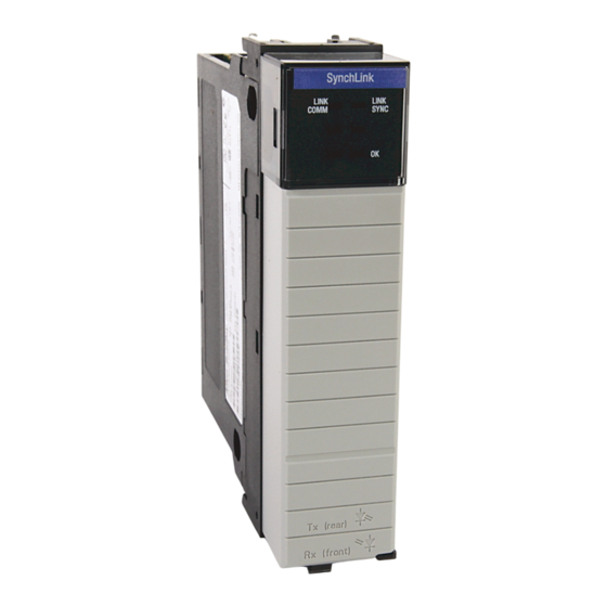
Chapter Using Specific Products on SynchLink This chapter describes the products that can be used on SynchLink. For information about: See page: ControlLogix SynchLink Module (1756-SYNCH) ControlLogix Drive Modules (1756-DMxxx Series) PowerFlex 700S Drive Connecting Products to SynchLink Configuring Products for Use on SynchLink 3-11 ControlLogix SynchLink A ControlLogix SynchLink module resides in a ControlLogix chassis... -
Page 28: Transferring Data With The Synchlink Module
Transferring Data With the SynchLink Module The SynchLink module transfers multiple types of reference data between chassis, including: · Direct - Data delivered in a single message. A SynchLink message can contain a maximum of four direct data words; each word is 32 bits in length. -
Page 29: Controllogix Drive Modules (1756-Dmxxx Series)
ControlLogix Drive The 1756-DM Drive Module is a single slot ControlLogix-based module for interface to Reliance Electric Distributed Power System Modules (1756-DMxxx (DPS) drive equipment. Each drive module interfaces with an Series) individual Power Module Interface (PMI) chassis, performing velocity, position, and torque control. -
Page 30: Transferring Data With The Drive Modules
Transferring Data With the Drive Modules The Drive modules transfer two types of data: · Direct - Data delivered in a single message. A SynchLink message can contain a maximum of four direct data words; each word is 32 bits in length. Direct data can be automatically forwarded to the next SynchLink node in the daisy chain or ring configurations. -
Page 31: Powerflex 700S Drive
PowerFlex 700S Drive The PowerFlex 700S is a highly functional, cost-effective and flexible drive control. The drive offers: · selectable, high performance motor control algorithms. · velocity, position and torque control · control loops synchronized to SynchLink · an array of feedback options, including encoder, resolver and high resolution encoder to optimize the accuracy of speed and position regulators. -
Page 32: Powerflex 700S Drive Features
PowerFlex 700S Drive Features The PowerFlex 700S drive offers the following features: · Adaptive, field-oriented control FOC maintains torque control accuracy without external motor sensors · Inertia compensation reduces dynamic tracking errors · Adjustable backlash compensation for both feedback and forward signal paths ·... -
Page 33: Connecting Products To Synchlink
Connecting Products The ControlLogix SynchLink module, ControlLogix Drive modules and PowerFlex 700S drives connect to SynchLink through special to SynchLink SynchLink fiber optic cables and other components, such as base blocks, splitter blocks and bypass switch blocks. SynchLink Hub The SynchLink hub is a modular fiber repeater containing base and splitter blocks, as shown in Figure 3.1. -
Page 34: Synchlink Bypass Switch Block
SynchLink Bypass Switch Block The SynchLink bypass switch block (1751-SLBP) is a DIN-rail mounted block that is used in daisy chain and ring configurations where a node, or group of nodes, needs to be temporarily disconnected from SynchLink without physical reconfiguration of the cable system. The bypass switch block requires 24V dc. - Page 35 The bypass switch block has no capabilities to detect or correct communication error conditions that may exist during the course of pass-through or bypass operation. The bypass switch block has no ability to report any abnormal conditions to the local station. The Bypass Switch should be applied as a SynchLink IMPORTANT patch when a local node needs to be powered down...
-
Page 36: Fiber Optic Cables
3-10 Fiber Optic Cables The SynchLink fiber optic cable assemblies are manufactured from 200/230 micron/simplex cable with a Versalink (V-Link) V-pin connectors at the ends. For a list of cable assembly specifications, see Table 3.2. For a complete list of SynchLink fiber optic cable system products, see Table 7.1 on page 7-2. -
Page 37: Configuring Products For Use On Synchlink
3-11 Configuring Products for You must electronically (i.e. via software) configure the devices in each set-up. Use on SynchLink · For the ControlLogix SynchLink module, you must use RSLogix 5000 to configure SynchLink. For more information on how to use RSLogix 5000 to configure your 1756-SYNCH module, see the ControlLogix SynchLink Module user manual, publication 1756-UM521. - Page 38 3-12 Notes: Publication 1756-TD008A-EN-P - August 2002...
-
Page 39: Difference Between Topologies And Configurations
Chapter Specific SynchLink Configurations This chapter describes the configurations available with each topology. The configurations listed in this chapter were tested and approved. If you plan to use another configuration, contact Rockwell Automation first. For information about: See page: SynchLink Functionality in Each Device Star Topology Configurations Daisy Chain Topology Configurations Ring Topology Configurations... -
Page 40: Synchlink Functionality In Each Device
SynchLink Functionality in Table 4.1 gives a summary of the various levels of functionality for the devices that use SynchLink. More detailed descriptions of each level of Each Device functionality follow the table. Table 4.1 SynchLink Functionality in SynchLink Devices Device: SynchLink Node Coordinated... -
Page 41: 1756-Dmxxx Drive Modules
CST/SynchLink Time Relay A time relay is any device that passes a time reference along. The 1756-SYNCH module passes the CST reference in the master chassis from the chassis backplane to the fiber optic media. Slave nodes in other chassis receive the CST reference value from the media, and relay the value to their respective backplanes. - Page 42 Coordinated System Time The 1756-DMxxx drive modules use the CST differently than the 1756-SYNCH module. You should be aware of two significant differences before implementing these modules in a control scheme. First, the 1756-DMxxx drive modules are intelligent processing modules that regulate Reliance Electric Distributed Power type drives. Each 1756-DMxxx drive module has integrated Velocity and Position Loops (VPL) that are a part of the module’s firmware for controlling the drives.
-
Page 43: Powerflex 700S Drive
PowerFlex 700S Drive SynchLink Node Clock The PowerFlex 700S drive employs the SynchLink node clock, allowing the drive to be the SynchLink time master or a SynchLink time slave; in this way, the drive can either set time on the fiber, or, receive time from the fiber. -
Page 44: Star Topology Configurations
Star Topology Configurations In the star topology, a hub is placed in the physical center of the link. The hub acts as a multi-port repeater that contains one receive port and up to 16 transmit ports. The master node transmitter is connected to the hub receive port. - Page 45 Star Topology Configuration #2 In this configuration, a ControlLogix SynchLink module (1756-SYNCH) is the master node, and PowerFlex 700S drives are the end nodes. Figure 4.2 ControlNet Master Node SynchLink End Node End Node 43181 End Node End Node End Node End Node Table 4.3 lists more information about this configuration.
- Page 46 Star Topology Configuration #3 In this configuration, PowerFlex 700s drives are the master and end nodes. Figure 4.3 Master Node ControlNet SynchLink End Node End Node End Node End Node End Node End Node 43092 Table 4.4 lists more information about this configuration. Table 4.4 Category: Explanation:...
-
Page 47: Daisy Chain Topology Configurations
Daisy Chain Topology Configurations In the daisy chain topology, the SynchLink system starts at the master node and ends at an end node but may also include center nodes that receive and transmit data; the only difference between center and end nodes is their physical location. - Page 48 4-10 Daisy Chain Topology Configuration #2 In this configuration, a ControlLogix SynchLink module is the master node, and ControlLogix SynchLink modules are the center and end nodes. Figure 4.5 1756-SYNCH 1756-SYNCH 1756-SYNCH 1756-SYNCH Center Center Master Node Node Node Node SynchLink ControlNet 43271...
- Page 49 4-11 Daisy Chain Topology Configuration #3 In this configuration, the ControlLogix SynchLink module is the master node, and PowerFlex 700s drives are the center and end nodes. Figure 4.6 Master Center Center Node Node Node Node ControlNet SynchLink 43093 Table 4.7 lists more information about this configuration. Table 4.7 Category: Explanation:...
- Page 50 4-12 Daisy Chain Topology Configuration #4 In this configuration, PowerFlex 700s drives are the master, center and end nodes. Figure 4.7 Master Node Center Node Center Node End Node SynchLink ControlNet 43094 Table 4.8 lists more information about this configuration. Table 4.8 Category: Explanation:...
-
Page 51: Ring Topology Configurations
4-13 Ring Topology Configurations The ring topology is a permutation of the daisy chain configuration. In the ring topology, the end node’s transmitter is connected to the master node’s receiver. This topology can include center nodes; the only difference between the center and end nodes is their physical location. - Page 52 4-14 Ring Topology Configuration #2 In this configuration, PowerFlex 700s drives are the master, center and end nodes. Figure 4.9 Master Node Center Node Center Node Center Node SynchLink ControlNet 43096 Table 4.10 lists more information about this configuration. Table 4.10 Category: Explanation: Time synchronization...
-
Page 53: Additional Configurations
4-15 Additional Configurations Multiple SynchLink Connections in a Single Chassis In this specialty configuration, ControlLogix SynchLink modules are master and end nodes. Multiple modules (located in the first two chassis after the hub) transfer data to the last chassis. Figure 4.10 SynchLink ControlNet 1756-SYNCH... - Page 54 4-16 Star/Daisy Chain Combination When using this specialty configuration, you can transition from a star to a daisy chain configuration or from a daisy chain to a star configuration. The rules of star and daisy chain configurations apply to the individual portions. For more information on each, see page 2-2 (Star Topology) and page 2-3 (Daisy Chain Topology).
- Page 55 4-17 Drive Module Focus In this configuration: · SynchLink modules are required if you want to synchronize the Drive modules between chassis. · Drive module SynchLink connections pass data and SynchLink node clock timing information. Drive modules synchronize their clocks to the CST reference on the ControlLogix backplane. Figure 4.12 SynchLink 1756-DMxxx...
- Page 56 4-18 Drive Module/PowerFlex 700s Drives Combination In this configuration, a SynchLink module acts as a time relay and synchronizes the CST with the beacon to communicate data to the Drive modules and the PowerFlex 700s drives. The Drive modules use the CST to synchronize their VPLs, and the PowerFlex 700S drives use the SynchLink node clock to synchronize their VPLs.
-
Page 57: Chapter Summary
4-19 Chapter Summary In this chapter you read about SynchLink configurations. Chapter 5 offers an Overview of the SynchLink Fiber Optic Cable System. Publication 1756-TD008A-EN-P - August 2002... - Page 58 4-20 Publication 1756-TD008A-EN-P - August 2002...
- Page 59 Chapter Overview of the SynchLink Fiber Optic Cable System This chapter offers an overview of the SynchLink fiber optic cable system. For more information about: See page: Applying the SynchLink System Analyzing your SynchLink Application Identifying System Components Planning System Installation Installing the System Powering your System To successfully apply the concepts and techniques in...
-
Page 60: Applying The Synchlink System
Applying the SynchLink The following steps outline how to apply the SynchLink fiber optic cable system. System If you are going to use fiber optic cable in an IMPORTANT intrinsically safe area, consult with your local safety coordinator. 1. Analyze your SynchLink application and choose a SynchLink topology. - Page 61 SynchLink Fiber Optic Cable System The SynchLink fiber optic cable system is designed to be user-constructed and installed. To take full advantage of this flexibility, you should spend sufficient time planning your system’s installation before assembling any of the hardware. The time and effort spent on planning your cable system installation will be insignificant compared to the time and effort required to locate and repair damaged or improperly installed hubs, cables, and/or other...
-
Page 62: Identifying System Components
Identifying System Components The SynchLink fiber optic cable system is comprised of these components: · Cable Assemblies · Base Blocks · Splitter Blocks · Bypass Switches For more information on SynchLink fiber optic cable components, see Chapter 6, Planning a SynchLink Fiber Optic Cable System. Planning System Installation When planning your SynchLink fiber optic cable system installation: 1. -
Page 63: Powering Your System
Powering your System To power your SynchLink fiber optic cable system: 1. Connect cables to nodes, hubs, or bypass switches in accordance with your cable layout. 2. Power hubs and bypass switches in accordance with instructions provided in their installation instructions. Be certain that all blocks are attached and secured IMPORTANT prior to applying power to them. - Page 64 Notes: Publication 1756-TD008A-EN-P - August 2002...
-
Page 65: Chapter 6 Developing A Plan
Chapter Planning a SynchLink Fiber Optic Cable System Read this chapter to plan your SynchLink fiber optic cable system installation. For more information about: See page: Developing a Plan Selecting a Topology Planning Installation of the System Components Estimating Cable Lengths Developing a Plan The SynchLink fiber optic cable system is designed to be user-constructed and installed. -
Page 66: Selecting A Topology
Selecting a Topology The first step to using fiber media is to analyze your application and determine the topology of your SynchLink system. Table 6.1 offers a brief description of each SynchLink topology. For more information on each of the SynchLink topologies, see Chapter 2, SynchLink Topologies. -
Page 67: Planning Installation Of The System Components
Planning Installation of the To achieve maximum signal quality and cable protection in a specific environment with minimum cable usage, follow these steps: System Components 1. Determine how many nodes will be in the SynchLink system. 2. Select the topology. 3. -
Page 68: Estimating Cable Lengths
Estimating Cable Lengths The SynchLink system requires the use of pre-terminated cable assemblies. SynchLink fiber optic cable segments are limited to a maximum of 300m. If your distance requirements are greater than 300m, you need to revise your floor plan. Avoid jointing your cable. - Page 69 Chapter Installing a SynchLink Fiber Optic Cable System This chapter describes how to install a SynchLink fiber optic cable system. For more information about: See page: Using Pre-terminated Fiber Cable Using Cable System Components Mounting and Removing Your Fiber Blocks When installing a SynchLink fiber optic cable ATTENTION system, remember the following:...
-
Page 70: Using Pre-Terminated Fiber Cable
Using Pre-terminated Rockwell Automation offers simplex pre-terminated cable assembles listed in Table 7.1. For information regarding other fiber products not Fiber Cable covered in this manual, consult your local fiber media distributor. Using Cable System SynchLink fiber optic cable systems are built using components listed in Table 7.1. - Page 71 Installation Guidelines for Fiber Blocks Follow these guidelines when you plan and install your fiber blocks: · Observe the environmental specifications for the fiber blocks as outlined in each installation instruction. · Avoid electrostatic and electromagnetic fields at installation sites. ·...
- Page 72 · The total length of the fiber optic cable should not exceed 300m. · In a star configuration, 300m is the maximum for any of the following cable segments: – between time master and base block – between time slave and splitter block –...
-
Page 73: Mounting And Removing Your Fiber Blocks
Mounting and Removing You can horizontally or vertically mount SynchLink blocks on a standard 35mm DIN rail. Your Fiber Blocks · To install the blocks, snap them on the DIN rail by hand. · To remove components from the DIN rail, use a flat-blade screwdriver. - Page 74 Publication 1756-TD008A-EN-P - August 2002...
- Page 75 Chapter Guidelines for SynchLink Fiber Optic Cable Installation This chapter describes guidelines for cable installation. For more information about: See page: Following General Rules for Safety Guidelines for Handling Fiber Optic Cable Direct Attachment Direct Attachment Indirect Attachment Conduit and Duct Installation Vertical Installation This guide describes cable installation inside of a IMPORTANT...
-
Page 76: Following General Rules For Safety
SynchLink fiber optic cable system. Many of our customers are qualified to plan and install their own SynchLink fiber optic systems. Rockwell Automation sells the necessary components to implement an application but we do not offer cable installation services. If your company does not have qualified staff to install fiber optic cable you should contract a specialist. - Page 77 Table 8.1 lists fiber optic cable handing guidelines. Table 8.1 Guidelines for Handling Fiber Optic Cable Guideline Description Minimum bend Observe the minimum fiber cable bend radius specified. radius Skin Contact Do not touch the ends of the fiber optic strands. The fiber can break easily and pierce your skin.
-
Page 78: Cable Protection And Isolation Recommendations
Cable Protection and The cable installation should conform to all applicable codes. Isolation Recommendations In order to successfully apply the concepts and IMPORTANT techniques contained in this manual, you must have a fundamental knowledge of electronics and electrical codes. Cable Protection The fiber optic cable must be properly handled prior to and during installation. -
Page 79: Physical Isolation
Physical Isolation Use the following guidelines to prevent physical damage and wear of the fiber optic cable: · Protect the cable from abrasion, vibration, moving parts, and personnel traffic. · Avoid intersecting a cable route with the regular routes of cranes, forklifts, and similar equipment. -
Page 80: Unterminated Cable Installation Guidelines
Unterminated Cable If you pull unterminated cable, pull it prior to connector installation; it becomes more difficult to protect fiber from stress after connectors Installation Guidelines have been mounted. Connectors may be pre-installed on one end, leaving the other end for pulling. Refer to the cable specifications and manufacturer’s cable pulling instructions for additional information. -
Page 81: Conduit And Duct Installation
Conduit and Duct Installation Installation procedures for conduit and wire duct installation of fiber optic cables are similar to those of electrical wires. Avoid yanking, flipping, or wrapping cables; this can cause unnecessary tightening. Fiber cable, electrical wires, small fiber optic cables should never be subjected to foot traffic or potentially crushing forces. - Page 82 9. Position the winch at the pull station to avoid a steep angle either entering the duct or exiting the cable tray. Do not exceed the maximum pulling tension for IMPORTANT your fiber optic cable. 10. Leave enough extra cable to route to the equipment rack, put connectors on, and allow for future repairs when your pull is complete.
-
Page 83: Vertical Installation
Vertical Installation The requirements of your application may require a vertical installation. You can install fiber optic cable vertically in trays, shafts, or towers. Dielectric cables are recommended for applications requiring high vertical installations. Plans for Vertical Cable Installation Use the following guidelines when planning a vertical cable installation. -
Page 84: Chapter Summary
8-10 Chapter Summary In this chapter you read about guidelines for fiber optic cable installation. Chapter 9 explains Maintenance and Troubleshooting. Publication 1756-TD008A-EN-P - August 2002... -
Page 85: Cable System Maintenance
Chapter Maintenance and Troubleshooting This chapter describes how to maintain and troubleshoot your fiber optic cable system. For more information about: See page: Cable System Maintenance Measuring Power Loss Cable System Maintenance Even if the installation is done properly, the SynchLink cable system may still experience some unexpected downtime. -
Page 86: Cable System Inspection
Cable System Inspection Inspect the cable system periodically, including testing cable loss as described in the next section. Make sure you properly document all tests. Measuring Power Loss You should test each cable segment before and after its installation to verify that cable attenuation does not exceed 12dB/km. - Page 87 Appendix Specifications This appendix lists specifications for the following products: · 1756-SYNCH SynchLink module · 1756-DMxxx Series Drive module · PowerFlex 700S Drive · 1751-SL4SP SynchLink 4-Port Splitter Block · 1751-SLBA SynchLink Base Block · 1751-SLBP SynchLink Bypass Switch Block Table 1.1 1756-SYNCH SynchLink Module Specifications Module Location...
- Page 88 Table 1.1 1756-SYNCH SynchLink Module Specifications 5 0m s Frame Period Indicators Green and red indicators for operation, status and diagnostics Environmental Conditions Operating Temperature 0ºC - 60ºC (32ºF - 140ºF) Storage Temperature -40ºC - 85ºC (-40ºF - 185ºF) Relative Humidity 5 to 95%, 0ºC - 60ºC non-condensing 30g peak acceleration, 11 ( ±...
- Page 89 Table 1.2 1756-DMxxx Drive Module Specifications Operating Wavelength SynchLink 650nM (red) Drive Communication 820nM (red) Data Rate SynchLink 5M bit/s Drive Communication 10M bit/s SynchLink Connecting Cable Fiber Type 200/230 micron HCS (Hard Clad Silica) Fiber Termination Type Versalink V-System Assemblies Cable assemblies can be ordered from Rockwell Automation, catalog number 1403-CFxxx (xxx =...
- Page 90 Table 1.3 PowerFlex 700S AC Drive and 700S DriveLogix AC Drive Specifications Operator LCD HIM places drive information in a 7-line by 21-character display that Interface supports a variety of languages 3-Phase Voltage 200-240V, 400-480V, 500-600V, 690V + 10% Common DC Bus 325V, 650V, 810V, 930V Voltage Ratings Frequency...
- Page 91 Table 1.3 PowerFlex 700S AC Drive and 700S DriveLogix AC Drive Specifications Dimensions Frame 2 389in x 200in x 200in (15.31mm x 7.87mm x 7.87mm) (HxWxD) and Power Class Amps Amps for Amps for 3s Ratings Continuous 20 to 25Hp 27 to 34 33 to 40.5 44 to 54...
- Page 92 Table 1.4 1751-SL4SP SynchLink 4-Port Splitter Block Specifications Communication Rate 5M bit/s Splitter Block Power Consumption 0.300 A @ 5.1V dc 5V dc input from 1751-SLBA Environmental Conditions Operating Temperature 0ºC - 60ºC (32ºF - 140ºF) Storage Temperature -40ºC - 85ºC (-40ºF - 185ºF) Relative Humidity 5 to 95%, 0ºC - 60ºC non-condensing 30g peak acceleration, 11 ( ±...
- Page 93 Table 1.5 1751-SLBA SynchLink Base Block Specifications Power Supply To comply with CE Low Voltage directives, you must use a Safety Extra Low Voltage (SELV) or a Protected Extra Low Voltage (PELV) power supply to power this base block. Use a NEC/CEC Class 2 power supply in order to comply with UL and CSA requirements.
- Page 94 Table 1.5 1751-SLBA SynchLink Base Block Specifications Agency Certifications Listed Industrial Control Equipment Certified Process Control Equipment Certified Class I, Division 2, Groups A, B, C, D Marked for all applicable directives Marked for all applicable acts N223 This product must be mounted within a suitable system enclosure to prevent personal injury resulting from accessibility to live parts.
- Page 95 Table 1.6 1751-SLBP SynchLink Bypass Switch Block Specifications Fiber Optic Cable Fiber Type 200/230 micron HCS (Hard Clad Silica) Fiber Termination Type Versalink V-System Assemblies Cable assemblies can be ordered from Rockwell Automation, catalog number 1403-CFxxx (xxx = length in meters); or from Lucent Technologies, Specialty Fiber Technologies division.
- Page 96 A-10 Publication 1756-TD008A-EN-P - August 2002...
-
Page 97: Appendix B Advantages Of Fiber
Appendix SynchLink Fiber Optic Cable Description Advantages of Fiber Fiber media holds many advantages over traditional copper media. Because fiber optic media transmits digitized information via light pulses over glass or plastic fibers, it avoids many of the problems common with copper applications. If you are going to use fiber in an intrinsically safe ATTENTION area, consult with your local safety coordinator. -
Page 98: Optical Fiber Construction
Optical Fiber Construction Optical fiber consists of three major elements: · buffer and coating · core · cladding as shown in Figure 2.1. For more information on the three major parts, see Table B.2. Figure 2.1 Coating Core Cladding Table B.2 Optical Fiber Description: Elements:... -
Page 99: Hard Clad Silica Fiber
Hard Clad Silica Fiber The SynchLink cable system is designed for use with a 200 micron Ò (step index multi-mode) Hard Clad Silica (HCS ) fiber. HCS fibers are coated with a patented hard polymer cladding that provides higher tensile strength, greater resistance to moisture, and lower microbending losses than conventional coatings. -
Page 100: Cable Assemblies
Cable Assemblies The SynchLink cable assemblies listed in Table B.4 are manufactured from 200/230 micron/simplex cable with a Versalink (V-Link) V-pin connections at the ends. · Never look into a transmitter’s output or the end ATTENTION of a cable with an active transmitter connected. ·... - Page 101 Glossary Attenuation The light loss of the fiber cable, specified in dB/km. Base Block A block that converts optical signals received from a SynchLink node into electrical signals and then “retimes” and “retransmits” the signals simultaneously to a maximum of four splitter blocks. The base block also supplies power to splitter blocks.
- Page 102 Glossary Bypass Switch Block A block used in the daisy chain and ring configurations to bypass a node temporarily disconnected from the SynchLink system. Center node A node in the SynchLink Daisy Chain or Ring configuration that receives data and transmits data. Cladding A layer of material surrounding the core of a fiber.
- Page 103 Glossary Core The central cylinder of a fiber that is made of plastic or glass. Daisy chain configuration SynchLink configuration that begins with a master node and ends at an end node. Center nodes may be used between the master and end in this configuration.
- Page 104 Glossary Electronic keying A system feature which makes sure that the physical module attributes are consistent with what was configured in the software. Exact match An electronic keying protection mode that requires the physical module and the module configured in the software to match identically, according to vendor, catalog number, major revision and minor revision.
- Page 105 Glossary Loss see Attenuation Major revision A module revision that is updated any time there is a functional change to the module resulting in an interface change with software. Master node A node in any SynchLink configuration that serves as the time master. Minor revision A module revision that is updated any time there is a change to the module that does not affect its function or software user interface...
- Page 106 Glossary Receiver Device that produces logic levels in a fiber optic system by using photo diodes, resistors, amplifiers, and level shift circuits. Remote Axis Data Motion data used by the motion planner in the controller. The 1756-SYNCH module can consume an Axis tag from a controller and pass it over SynchLink.
- Page 107 Glossary SynchLink A unidirectional fiber optic communications link that provides time synchronization and data broadcasting. These functions are used for distributed motion and coordinated drive control systems based on ControlLogix and PowerFlex 700S products. SynchLink Fiber Optic Cable System A fiber optic cable system consisting of cable segments and (depending on topology), hubs, or bypass switches.
- Page 108 Glossary Time relay A device that is configured to pass a time reference between a ControlLogix chassis backplane and a SynchLink fiber. Time slave A device (e.g. SynchLink module) that is configured to receive the time reference from the CST Time Master (located in a ControlLogix chassis) or upstream node in a SynchLink system.
- Page 109 Index Numerics As affects fiber optic cable installation 1751-SL4SP Specifications 3-11 Configuring SynchLink 1751-SLBA Specifications Using DriveExecutive 1751-SLBP Specifications Using RSLogix 5000 1756-DMxxx Series Module ControlLogix Clock 1-4 1-5 1756-DMxxx Series Specifications Using the CST 1-4 1-5 1756-SYNCH Module Coordinated System Time Usage in the drive module 1756-SYNCH Specifications Usage in the SynchLink module...
- Page 110 Direct Words Installing conduit and duct Measuring power loss across the system Directly Attaching Unterminated Cable Physical isolation Documentation Planning system installation Drive module Powering the system Preface-3 7-4 For related products Preterminated fiber cables PowerFlex 700S drive Protecting the cable SynchLink module System maintenance 3-11...
- Page 111 Physical isolation for fiber optic cables Reliance Electric Distributed Power Thermal isolation for fiber optic cables System Connecting to the drive module Removal and Insertion Under Power (RIUP) Drive module Maintenance of Fiber Optic Cable SynchLink module System 1-2 1-3 Ring Topology Master Clock 4-13...
- Page 112 4-15 Additional configurations Transmitting buffered data Daisy chain topology Transmitting direct data Ring topology Transmitting the multiplier Star topology Transmitting the multiplier overflow With the drive module With the PowerFlex 700S drive With the SynchLink module Testing Preterminated Cables Troubleshooting Thermal Isolation for Fiber Optic Cables Fiber optic cable system 1-3 1-4...
- Page 113 How Are We Doing? Your comments on our technical publications will help us serve you better in the future. Thank you for taking the time to provide us feedback. You can complete this form and mail it back to us, visit us online at www.ab.com/manuals, or email us at RADocumentComments@ra.rockwell.com Pub.
- Page 114 PLEASE FASTEN HERE (DO NOT STAPLE) Other Comments PLEASE FOLD HERE NO POSTAGE NECESSARY IF MAILED IN THE UNITED STATES BUSINESS REPLY MAIL FIRST-CLASS MAIL PERMIT NO. 18235 CLEVELAND OH POSTAGE WILL BE PAID BY THE ADDRESSEE...
- Page 116 ControlLogix, DriveExecutive, DriveTools, PowerFlex, SynchLink and RSLogix 5000 are trademarks of Rockwell Automation. Publication 1756-TD008A-EN-P - August 2002 PN 957707-27 Copyright © 2002 Rockwell Automation. All rights reserved. Printed in the U.S.A.
Need help?
Do you have a question about the Allen-Bradley SynchLink 1756-DM Series and is the answer not in the manual?
Questions and answers