
Related Manuals for Getinge Arjohuntleigh RotoRest System


Summary of Contents for Getinge Arjohuntleigh RotoRest System
-
Page 1: Operating Instructions
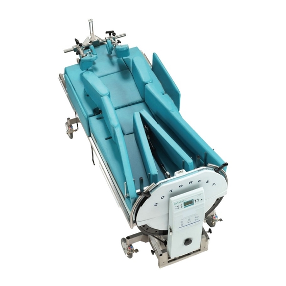
RotoRest System Operating Instructions ...with people in mind M6252253-AH Rev A • 01/2015... -
Page 2: Table Of Contents
Contents IntroduCtIon ........................1 The System at a Glance ..........................1 System Components ..........................1 System Features ............................1 Features ..................................1 Intended Use .............................. 1 Indications ................................. 2 Contraindications ..............................2 Safety Precautions ..............................2 Applications ................................2 Connecting the system to other devices ....................2 Devices That can be Used in Conjunction to This System ................ - Page 3 oPeratIon ........................14 Procedure for a Cardiopulmonary Resuscitation (CPR) ..............14 Following Cardiopulmonary Resuscitation and Stabilization of the Patient ......14 The Operating Panel ..........................15 Menu / Select Button ............................15 Cancel / Alarm Reset Button ..........................15 Cursor Buttons ...............................15 Operating Elements for the Hydraulic System ...................16 Button for Training Mode ...........................16 Menu Structure of the Display .........................16 Menu Structure of the Display .........................17...
- Page 4 PatIent Care ........................39 Bathing the Patient ..........................39 After Bathing the Patient ........................39 Skin Care ..............................39 Access Hatches ............................40 Arm Access Hatches .............................40 Hip / Leg Access Hatches ...........................40 Head Access Hatch ...............................41 Thorax Access Hatch ............................41 Posterior Access Hatch ............................41 Bladder Emptying ..............................41 Intestinal Voiding ..............................42 Respiratory Toilet ..............................42...
-
Page 5: Introduction
Introduction This chapter provides a general overview of the RotoRest™ system. In addition to a description of the functions and intended use of the system, the system components are also explained. The system's compatibility with other devices, the components that can be connected to the system and the components to which the system can be connected are also covered. -
Page 6: Indications
Indications The RotoRest System is indicated for the treatment and prevention of pulmonary complications as a result of immobility and is suitable for adult patients with: ■ Thorax trauma or rib fractures ■ Lumbar vertebra fracture ■ Cervical or skeletal extension after primary stabilization Contraindications The RotoRest System must not be used for: ■... -
Page 7: Safety
Safety This chapter contains information on the general safety precautions for the use of the system as well as recommendations for the patient's minimum or maximum body weight and height. General Safety Precautions The RotoRest system should not be used in combination with an oxygen tent. ■... -
Page 8: Lock Pin
Lock Pin The arresting bolt should be pushed in whenever automatic rotation is deactivated. Head and Shoulder Immobilization Set The securing wing nuts on both sides of the head and shoulder immobilization set should always be tightened securely to prevent any displacement of the immobilization pads along the retainers. -
Page 9: Fire Hazard Prevention
Fire Hazard Prevention To minimize the fire hazard, connect the unit's mains cable to a wall socket. Do not use extension cables or power strips. Read and follow the relevant European safety directives. Transportation The bed should always be transported by a minimum of two persons. Hazard Protection Fluids Make sure that no fluids get onto the system's electrical components. -
Page 10: Preparing For Use
Preparing for use This chapter describes the steps required to prepare the RotoRest system for use. Before you prepare the RotoRest system for use, check the system for damage or parts that cannot be maintained. Bed Pad Arrangement Head pad Left arm pad Thorax pad Posterior pad... -
Page 11: Support Pad Arrangement
Support Pad Arrangement Holder for respiratory tube and retainer for cervical extension fixture Head support pad Shoulder restraint Thorax supports Arm supports Arm positioning pad Knee supports Hip / leg supports Leg positioning Abduction pad Foot supports... -
Page 12: Access Hatch Arrangement
Access Hatch Arrangement Subframe Detent for arm Locking lever for Detent for hip / leg access hatch hip / leg supports access hatch Bag holder Openings for Detents for head Locking lever for catheter access hatch thorax supports Detents for posterior access hatch Frame rail Wheel... -
Page 13: Preparing The System For Use
Preparing the System for Use Remove any counterweights located on the frame rail and place them on the horizontal rail of the castor frame. Release lever for the drive belt Drive belt Lock pin Make sure that the bed is in the horizontal position. Disengage the drive by pushing one of the release levers for the drive belt ■... -
Page 14: Preparing To Position The Patient
Preparing to Position the Patient Remove the knee supports by pulling out the pin and withdrawing the shaft from the square tube of the abduction retainer. Remove the positioning pads for the arms and legs. Arm and leg positioning pads Knee supports... - Page 15 Remove the side arm supports by pulling them off the bed in a vertical direction. Place all side supports in the outermost lateral position before removing them. This makes them easier to re-attach and adjust at a later time. Loosen the locking lever for the thorax supports on the underside of the bed. ■...
- Page 16 Remove the other side arm support pads by pulling them off the bed in a vertical direction. Remove the abduction pad by pushing it towards the head end of the bed and loosen it from the foot support retainer and from the securing bolts on the abduction retainer.
- Page 17 Loosen the retainer for the foot supports by pulling the clamping lever upwards. The retainer will then slide free in its rail. Slide it all the way to the foot end of the bed. Retainer for foot support pad Clamping lever Abduction retainer Clamping lever...
-
Page 18: Operation
Operation This chapter describes the operation of the RotoRest system, how to handle and navigate through the various screens and how to safely switch the system on and off. Procedure for a Cardiopulmonary Resuscitation (CPR) Move the bed to the horizontal position and push in the lock pin. Lower the frame to a comfortable working height. -
Page 19: The Operating Panel
The Operating Panel The operating panel is at the foot end of the bed and features several buttons, a display and various indicator lamps. The button functions are described below: POWER ROTATION ON MODEL IV FOR TRAUMA AND INTENSIVE CARE LEFT RIGHT CURRENT ANGLE... -
Page 20: Operating Elements For The Hydraulic System
Operating Elements for the Hydraulic System These buttons are used to raise and lower the bed. Button for Training Mode This button is used to switch the bed to training mode. Rotation begins at 30° and is then gradually increased until the required rotation angle is reached. -
Page 21: Menu Structure Of The Display
Menu Structure of the Display 62° < 23° 59° Timed out 00:24 > Operating display Set angle Set holding time Display Status > Rotation time Trendelenburg angle Holding time > Change left 02 min Change right 14 min Confirm change Holding time Left 00 min... -
Page 22: Mechanical Operating Elements
Mechanical Operating Elements Lock Pin The lock pin is at the foot end of the bed. The lock pin is used to mechanically lock the bed in position at different predetermined angles. When the lock pin is engaged in one of the openings in the drive, the power supply to the motor is interrupted. -
Page 23: The Operating Unit
The Operating Unit The bed has a menu-controlled operating unit, which is used as follows. Please also refer to the menu structure diagram. Operating Display Once the bed is switched on, the operating display appears on the screen. The screen illustrated in the example shows the bed rotating to the left (flashing arrow). 62°... -
Page 24: Setting The Maximum Rotation Angle
Setting the Maximum Rotation Angle To change the angle setting for the right or left side, proceed as follows: Press the Menu / Select button. Operating display > Set angle Set holding time Display Status Press the down cursor key ↓ to move the arrow to, Set angle. Press the Menu / Select button to view the following screen. -
Page 25: Zeroing The Timer
Zeroing the Timer Lock the bed in the horizontal position. Make sure that the lock pin is pushed all the way in and that the screen displays, Bed Locked. Press the Menu / Select button to view the menu screen. Move arrow to, Display Status, and press the Menu / Select button. -
Page 26: Setting Holding Times
Setting Holding Times To set holding times for the left or right hand side, proceed as follows: Press the Menu / Select button. Operating display Set angle > Set holding time Display Status Press the down cursor key ↓ twice to move the arrow to, Set Holding Time. Press the Menu / Select button. -
Page 27: Checking The Bed Settings (Display Status)
Checking the Bed Settings (Display Status) Press the Menu / Select button to view the menu screen. Move the arrow to, Display Status, and press the Menu / Select button. Operating display Set angle Set holding time > Display Status >... -
Page 28: Setting The Trendelenburg Angle
To check the setting for the Trendelenburg angle, move the arrow to Trendelenburg Angle. Press the Menu / Select button to view the following screen. Rotation time > Trendelenburg angle Trendelenburg angle Holding time 08° To check the settings for the holding times, move the arrow to, Holding Time, and press the Menu / Select button. -
Page 29: Alarm And Warning Messages
Alarm and Warning Messages To guarantee a higher level of safety for patients and to make caregivers aware of potential hazards, the bed features various alarm functions. The following alarms can be triggered: Side Supports Fixed? If the RotoRest system is stopped but the lock pin is not fully pushed into one of the openings of the drive, the message, Bed Locked, appears on the screen. -
Page 30: Obstacle Alarm
Obstacle alarm Two situations can cause the bed to block. The bed rotates away from its zero (horizontal) position. If the bed platform hits an obstacle, the bed will stop and an alarm will ■ sound. The screen displays the message, Obstruction Alarm. The bed returns to its zero position, where it remains. -
Page 31: Positioning The Patient
Positioning the Patient This chapter describes in detail the procedure for safely positioning the patient in the RotoRest system. Before patients are transferred to the RotoRest system, nursing staff should familiarize themselves with the information given in the Safety and Operation chapters of these instructions, and read the procedures described below. - Page 32 Move the patient into the center of the support surface by lining up the patient's nose, navel and pubic region with the center of the bed. The patient must be lying in the center of the support surface to prevent imbalance. Otherwise, it is difficult to control the manual rotation of the bed.
- Page 33 Place a leg positioning pad beneath each calf so that the heel is free of the pad. The patient's heels should be relieved with a suitable support material to prevent bed sores developing.
- Page 34 Attach the abduction pads so that they are positioned just above the patient's knee joints. Fasten them by pushing the clamping lever down. Attach the foot supports to the foot retainer, as shown in the image. Foot supports Clamping lever Foot support retainer As the rotational movement does not relieve the pressure on the soles of the...
- Page 35 Attach the leg abduction pads by placing the narrow pointed ends into their positioning openings on the foot support pad retainer and attaching the opposite ends at the locking lever on the abduction retainer. Attach the leg and hip supports to their respective retainers and adjust them so that they are in close contact with the patient's hips.
- Page 36 Carefully lower the head and shoulder pad set until it is in contact with the pads. Carefully slide the unit until it is touching both sides of the patient's head. Adjust the head pad so that the patient's ears are free. The head pad can be moved in any direction and allows the use of an extension clamp.
- Page 37 Firmly tighten the restraints on the crossbeam in order to secure the pad sets in the correct lateral position. Attach the arm supports as shown in the image. Arm support Fasten the arm supports to the openings located in the frame. With larger patients, attach the arm supports so that the front edge closes on the label with the line below the symbol for, large person.
- Page 38 Fasten the two safety straps as shown in the image. Safety strap Guide the urinary catheter and the thorax drainages through the corresponding openings, see Access Hatch Arrangement in the Preparation for Use section.
-
Page 39: Patient-Specific Settings
Patient-specific Settings Counterweights The counterweights are required for patients weighing over 75 kg. They are attached to the frame rail immediately below the posterior access hatch in order to keep the bed balanced. An additional counterweight is required for every 10 kg of bodyweight over 75 kg. Example: For a patient weighing 125 kg, five weights must be attached to the frame rail. -
Page 40: Adjusting The Support Pads
The bed should be kept rotating continuously except when treatment is being administered. In the event of a power failure or a motor malfunction, the bed can be rotated by hand and locked every 30 minutes, or as required, in the lateral or center position, in order to prevent bed sores from developing. -
Page 41: Thorax X-Ray Imaging
Thorax X-ray Imaging Move the bed into one of the two maximum lockable lateral positions and lock in place. Use one hand to compress the spring-loaded detents on the thorax access hatch. The hatch will open. With your other hand, allow the access hatch to slide down until it is resting on the frame rail. -
Page 42: Drip Stands (Available As Accessories)
If the thorax drainage system is placed under the bed, check that it does not obstruct bed rotation. It is absolutely essential to use tubes of adequate length so that when the bed is rotated, no tension is applied to the thorax catheter or the drainage system. -
Page 43: Patient Care
Patient Care This chapter describes general patient care procedures. Bathing the Patient Move the bed to the horizontal position and push in the lock pin. ■ If necessary, remove the positioning pads to gain access to the front ■ of the body and to the patient's limbs. Wash and dry the patient as normal. To wash the patient's dorsal surface, open one each of the access hatches in the ■... -
Page 44: Access Hatches
Access Hatches One of the bed's outstanding features is the special arrangement of access hatches underneath the bed, which provide access to the patient's entire dorsal surface without having to move the patient. Detent for hip / leg Detent for arm Locking lever for access hatch access hatch... -
Page 45: Head Access Hatch
Head Access Hatch The back of the patient's head can be accessed through this hatch. For hair washing, hair care and skin care on the scalp and neck, proceed as follows: Rotate the bed into the maximum lockable lateral position and secure it in that position. -
Page 46: Intestinal Voiding
Intestinal Voiding Continuously rotating the patient stimulates peristalsis, so more frequent intestinal voiding can therefore be expected. Proceed as follows to slide the bed pan beneath the patient: Rotate the bed to its maximum lockable lateral position. Open the posterior access hatches and secure the upper hatch using the integral strap. -
Page 47: Cleaning And Care
Cleaning and Care This chapter describes the general cleaning and care of the RotoRest system. Scheduled, non- scheduled and preventive maintenance are included. This chapter also contains information on how to transport and store the system when not in use. The cleaning methods recommended by the manufacturer for the RotoRest system, as well as procedures for regular system maintenance during use are described below. -
Page 48: Transport
Transport The system must be completely lowered. To lower the head and foot part, the buttons marked Head / Foot must be pressed and held until the main frame is in contact with the castor frame; this prevents the hydraulic cylinders having to support the load of the patient support surface during transport. -
Page 49: Specifications
Specifications This chapter contains the technical specifications for the RotoRest system, as well as data on replacement parts. Technical Specifications Equipment not suitable for use in the presence of a flammable anesthetic mixture with air, oxygen or nitrous oxide. When using half-bed-length type oxygen administering equipment, ensure that side rails are not contained in oxygen enriched environment. -
Page 50: Explanations Of Symbols Used
Explanations of Symbols Used Important information for operation Application part Type B Equal Potential The RotoRest system conforms to the Directive on Medical 0086 Devices Dangerous Voltage (93 / 42 / EEC). Alternating current Important - Observe accompanying documentation Manufacturer... -
Page 51: Customer Contact Information
CuStomer ContaCt InformatIon For questions regarding this product, supplies, maintenance or additional information about ArjoHuntleigh products and services, please contact an ArjoHuntleigh authorized representative or visit www.ArjoHuntleigh.com. ® ™ are trademarks belonging to the ArjoHuntleigh group of companies © ArjoHuntleigh 2015. P/N M3252253-AH Rev A 01/2015... - Page 52 Getinge Group is a leading global provider of products and systems that contribute to quality enhancement and cost efficiency within healthcare and life sciences. We operate under the three brands of ArjoHuntleigh, Getinge and Maquet. Getinge provides solutions for infection control within healthcare and contamination prevention within life sciences.
Need help?
Do you have a question about the Arjohuntleigh RotoRest System and is the answer not in the manual?
Questions and answers