Table of Contents
Advertisement
Quick Links
Advertisement
Table of Contents

Related Manuals for Advantech ER75s


Summary of Contents for Advantech ER75s
- Page 1 EDGE router ER75s USER MANUAL...
- Page 2 Source codes under GPL licence are available free of charge by sending an email to: cellularsales@advantech-bb.com. Advantech B+B SmartWorx s.r.o., Sokolska 71, 562 04 Usti nad Orlici, Czech Republic Document No. MAN-0033-EN, revision from January 17, 2019. Released in the Czech Republic.
-
Page 3: Table Of Contents
ER75s Contents 1 Safety Instructions 2 WEEE directive 3 Description of the router 4 Contents of package 5 Router design 5.1 Delivery identification ....... . - Page 4 ER75s 8.1.1 Mobile Connection ......8.1.2 Primary LAN ....... . .
- Page 5 ER75s 8.34 Update firmware ........8.35 Reboot .
- Page 6 ........Label for ER75s .
- Page 7 ER75s Example firewall configuration ......Topology of example NAT configuration 1 .....
- Page 8 ER75s List of Tables Delivery identification ....... . Description of the rear panel .
-
Page 9: Example Nat Configuration
ER75s OpenVPN tunnels configuration ......Example IPsec configuration ...... -
Page 10: Safety Instructions
ER75s 1. Safety Instructions Please, observe the following instructions: The router must be used in compliance with all applicable international and national laws and in compliance with any special restrictions regulating the utilization of the router in prescribed applications and environments. -
Page 11: Weee Directive
ER75s 2. Product Disposal Instructions The WEEE (Waste Electrical and Electronic Equipment: 2012/19/EU) directive was in- troduced to ensure that electrical/electronic products are recycled using the best available recovery techniques in order to minimize impact on the environment. This product contains high quality materials and components which can be recycled. -
Page 12: Description Of The Router
XP, Windows Vista or Windows Seven operating system. EDGE router is only available in one basic version called ER75s. Allows user to use one SIM card to connect to the GSM network and is embedded in a plastic box. -
Page 13: Contents Of Package
ER75s 4. Contents of package Basic delivered set of the router includes: router, power supply, crossover UTP cable, external antenna, clip for the DIN rail, paper start guide. Figure 1: ER75s router... -
Page 14: Router Design
Type name Other ER75s ER-75s Router with one SIM card in plastic box Table 1: Delivery identification Figure 2: Label for ER75s 5.2 Ordering codes Router is supplied in a single version, which can be ordered using this code: ER75s set. -
Page 15: Basic Dimensions
ER75s 5.3 Basic dimensions Figure 3: Basic dimensions 5.4 Mechanical dimensions and mounting recommendations Router is standardly designed for: mounting to a panel using through holes, possibility to be put on a work surface, mounting onto the DIN rail by the plastic clips, which are included. -
Page 16: Space Around Antennas
ER75s For compliance of EN 60439-1 ed.2:00 + A1:04 specification it is necessary to observe next assembly of the router to the switch – board: for whip antennas we recommend to observe a distance of 6 cm from cables and metal surfaces on every side according to the next picture due to the elimination of interfer- ence, while using an external antenna except for the switch-board it is necessary to fit a... -
Page 17: Cable Routing
ER75s Figure 5: Cable routing Sufficient space must be left before individual connectors for handling of cables, Figure 6: Space in front of connectors For correct function of the router we recommend to use in the switch-board earth- bonding distribution frame for grounding of power supply of router, data cables and... -
Page 18: Description Of Individual Components Of The Router
5.5.2 Control microcomputer The core of the ER75s router is a 32-bit microprocessor with 16 MB RAM, 4 MB FLASH EEPROM, serial interface RS232 and an Ethernet interface 10/100 Mbit/s. The microcomputer is connected to the MC75i OEM module through the serial interface and controls the commu- nication via GSM/GPRS. -
Page 19: Description Of The Front And Rear Panel
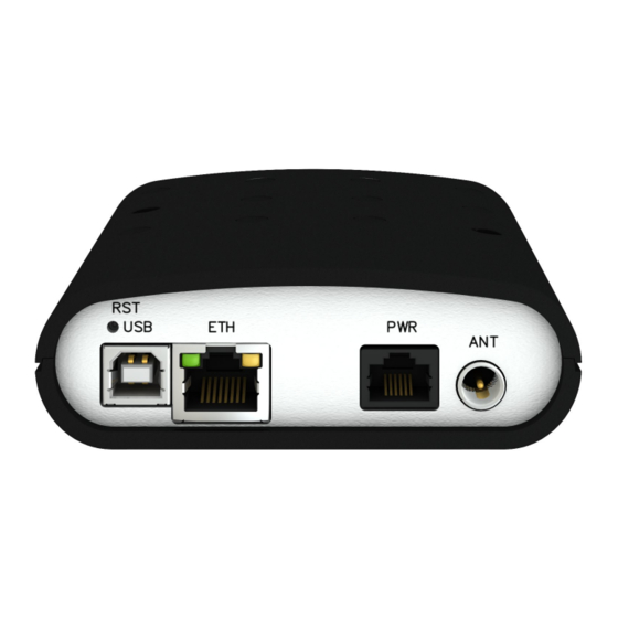
ER75s 5.6 Description of the front and rear panel On the front panel is located holder for the SIM card. On the rear panel of the router are located the following connectors: Caption Connector Description RJ12 Connector for the power supply adapter... -
Page 20: Status Indication
ER75s 5.6.1 Status indication Na pˇ r edním a zadním panelu routeru jsou dohromady tˇ r i kontrolky (LED diody), které infor- mují o stavu routeru. Na Ethernetovém portu pak jsou dv ˇ e kontrolky informující o stavu nebo aktivit ˇ e tohoto portu. -
Page 21: Antenna Connector Ant
ER75s 5.6.3 Antenna connector ANT Main antenna is connected to the router using the FME connector on the rear panel of the router. The connector is marked with ANT. The router can not operate without the connected main antenna. Example of antenna: Figure 10: External antenna 5.6.4 SIM card reader... -
Page 22: Eth Port
ER75s 5.6.5 ETH port Panel socket RJ45. Signal mark Description Data flow direction TXD+ Transmit Data – positive pole Input/Output TXD- Transmit Data – negative pole Input/Output RXD+ Receive Data – positive pole Input/Output — — — — RXD- Receive Data – negative pole Input/Output —... -
Page 23: Usb Port
ER75s 5.6.6 USB Port Panel socket USB-B. Signal mark Description Data flow direction +5 V Positive pole of 5 V DC supply voltage USB data - USB data signal – negative pole Input/Output USB data + USB data signal – positive pole... -
Page 24: Reset
ER75s 5.6.7 Reset It is important to distinguish between reset and reboot the router. Action Router behavior Invoking events Reboot Turn off and then turn on router Disconnect and connect the power, Press the Reboot button in the web configuration Reset Restore default configuration and reboot... -
Page 25: First Use
ER75s 6. First use 6.1 Connecting the router before first use Before you give up the router, it is necessary to connect all components needed for the operation of your applications and the SIM card must be inserted (see figure below). -
Page 26: Configuration
ER75s 6.3 Configuration Attention! If the SIM card is not inserted in the router, then it is impossible to operate. The inserted SIM card must have activated EDGE/GPRS. 6.3.1 Configuration over web browser Monitoring of the status, configuration and administration of the router can be performed by means of the web interface, which is available after insertion of IP address of the router into the web browser. -
Page 27: Technical Parameters
ER75s 7. Technical parameters 7.1 Technical parameters of router ER75s Complies with standards ETSI EN 301 511 V12.5.1 ETSI EN 301 489-1 V2.1.1 EN 55032:2015 Class A EN 60950-1:06 ed.2 + A11:09 + A1:10 Temperature range Function -30 C to +60 C... -
Page 28: Configuration Via Web Browser
ER75s 8. Configuration via web browser Attention! If the SIM card is not inserted in the router, then wireless transmissions will not work. The inserted SIM card must have activated GPRS. Insert the SIM card when the router is switched-off. -
Page 29: General
ER75s After green LED starts to blink it is possible to restore initial settings of the router by pressing button RST on front panel. If press button RST, configuration is restored to default and it is reboot (green LED will be on). -
Page 30: Peripheral Ports
ER75s 8.1.3 Peripheral Ports ER75s can be equipped with no expansion port, so in this section is always displayed this information: Expansion Port: None. 8.1.4 System Information Item Description Firmware Version Information about the firmware version Serial Number Serial number of the router (in case of N/A is not available) Profile... -
Page 31: Mobile Network Information
Cells Number of switch between cells Availability Availability of ER75s via the mobile network (expressed as a percentage) Table 14: Mobile Network Statistics Tips for Mobile Network Statistics table: Availability of connection to mobile network is information expressed as a percentage that is calculated by the ratio of time when connection to mobile network is established to the time when the router is turned on. -
Page 32: Mobile Wan Status
ER75s Item Description RX data Total volume of received data TX data Total volume of sent data Connections Number of connection to mobile network establishment Table 15: Traffic statistics The last part (Mobile Network Connection Log) informs about the mobile network connec- tion and problems in establishment. -
Page 33: Network Status
ER75s 8.3 Network status To view system information about the router operation, select the Network item in the main menu. The upper part of the window displays detailed information about active interfaces: Interface Description eth0, eth1 Network interfaces (ethernet connection) -
Page 34: Network Status
ER75s Continued from previous page Item Description collisions Number of collisions on physical layer txqueuelen Length of front network device RX bytes Total number of received bytes TX bytes Total number of transmitted bytes Table 17: Description of information in network status It is possible to read status of connection to mobile network from the network information. -
Page 35: Dhcp Status
ER75s 8.4 DHCP status Information on the activities of the DHCP server can be accessed by selecting the DHCP status item. The DHCP server provides automatic configuration of devices connected to the network managed router. DHCP server assigns to each device’s IP address, netmask, default gateway (IP address of router) and DNS server (IP address of router). -
Page 36: Ipsec Status
ER75s 8.5 IPsec status Information on actual IPsec tunnel state can be called up in option IPsec in the menu. After correct build the IPsec tunnel, status display IPsec SA established (highlighted in red) in IPsec status information. Other information is only internal character. -
Page 37: System Log
ER75s DynDNS server failure. For correct function DynDNS, SIM card of router must have assigned public IP address. 8.7 System log In case of any problems with connection to GPRS it is possible to view the system log by pressing the System Log menu item. In the window, are displayed detailed reports from indi- vidual applications running in the router. -
Page 38: Lan Configuration
ER75s Example of logging into the remote daemon at 192.168.2.115: Figure 23: Example program syslogd start with the parameter -r 8.8 LAN configuration To enter the network configuration, select the LAN menu item. Item Description IP address Fixed set IP address of network interface ETH. -
Page 39: Configuration Of Dynamic Dhcp Server
ER75s are filled-in by the user in the configuration form, they are preferred. DHCP server supports static and dynamic assignment of IP addresses. Dynamic DHCP server assigns clients IP addresses from a defined address space. Static DHCP assigns IP addresses that correspond to the MAC addresses of connected clients. -
Page 40: Topology Of Example Lan Configuration 1
ER75s Figure 24: Topology of example LAN configuration 1... -
Page 41: Example Lan Configuration 1
ER75s Figure 25: Example LAN configuration 1 Example of the network interface with dynamic and static DHCP server: The range of allocated addresses from 192.168.1.2 to 192.168.1.4. The address is allocated 10 minutes. Client’s with MAC address 01:23:45:67:89:ab has IP address 192.168.1.10. -
Page 42: Topology Of Example Lan Configuration 2
ER75s Figure 26: Topology of example LAN configuration 2 Figure 27: Example LAN configuration 2... -
Page 43: Topology Of Example Lan Configuration 3
ER75s Example of the network interface with default gateway and DNS server: Default gateway IP address is 192.168.1.20 DNS server IP address is 192.168.1.20 Figure 28: Topology of example LAN configuration 3 Figure 29: Example LAN configuration 3... -
Page 44: Vrrp Configuration
ER75s 8.9 VRRP configuration To enter the VRRP configuration select the VRRP menu item. VRRP protocol (Virtual Router Redundancy Protocol) is a technique, by which it is possible to forward routing from main router to backup router in the case of the main router failure. If the Enable VRRP is checked, then it is possible to set the following parameters. -
Page 45: Mobile Wan Configuration
ER75s ues the same way like in the case of standard testing process after first test message answer drops out. Example of the VRRP protocol: Figure 30: Topology of example VRRP configuration Figure 31: Example VRRP configuration — main router 8.10 Mobile WAN configuration... -
Page 46: Example Vrrp Configuration -- Backup Router
ER75s Figure 32: Example VRRP configuration -– backup router Item Description Network identifier (Access Point Name) Username User name to log into the GSM network Password Password to log into the GSM network Authentication Authentication protocol in GSM network: PAP or CHAP – authentication method is chosen by router PAP –... -
Page 47: Mobile Wan Connection Configuration
ER75s Continued from previous page Item Description Maximum Receiving Unit – It’s an identifier of maximum size of packet, which is possible to receive in a given environment. Default value is 1500 B. Other settings may cause incorrect transmission of data. -
Page 48: Dns Address Configuration
ER75s Tips for working with the Mobile WAN configuration form: If the size is set incorrectly, data transfer may not be succeeded. By setting a lower MTU it occurs to more frequent fragmentation of data, which means higher overhead and also the possibility of damage of packet during defragmentation. -
Page 49: Data Limit Configuration
ER75s In the case of the enabled option ping requests are sent on the basis of routing table. Thus, the requests may be sent through any available interface. If you require each ping request to be sent through the network interface, which was created on the occasion of establishing a connection to the mobile operator, it is necessary to set the Check Connection item to enabled + bind. -
Page 50: Configuration Of Switching Between Apns
ER75s 8.10.5 Configuration of switching between APNs At the bottom of configuration it is possible to set rules for switching between two APN’s on one SIM card. Item Description Default SIM card This parameter sets default APN, from which it will try to establish the connection to mobile network. -
Page 51: Configuration Of Switching Between Apns I
ER75s Continued from previous page Item Description Table 28: Configuration of switching between APNs I... -
Page 52: Dial-In Access Configuration
ER75s The following parameters define the time after which the router attempts to go back to the default APN. Item Description Initial timeout The first attempt to switch back to the primary APN shall be made for the time defined in the parameter Initial Timeout, range of this parameter is from 1 to 10000 minutes. - Page 53 ER75s the device behind router. For example from PC which is connected to ETH port router. There will be allot Ip address of SIM card to PC. The changes in settings will apply after pressing the Apply button.
-
Page 54: Mobile Wan Configuration
ER75s Figure 33: Mobile WAN configuration... -
Page 55: Example Of Mobile Wan Configuration 1
ER75s The figure below describes the situation, when the connection to mobile network is con- trolled on the address 8.8.8.8 in the time interval of 60 s for primary APN and on the address www.google.com in the time interval 80 s for secondary APN. In the case of traffic on the router the control pings are not sent, but the traffic is monitored. -
Page 56: Backup Routes
ER75s 8.11 Backup Routes Using the configuration form on the Backup Routes page can be set backing up primary connection by other connections to internet/mobile network. For each back up connection can be defined a priority. Own switching is done based on set priorities and state of the connection (for Primary LAN). -
Page 57: Backup Routes
ER75s Figure 37: Backup Routes Item Description Source IP address from which access to the router is allowed Protocol Specifies protocol for remote access: all – access is enabled for all protocols TCP – access is enabled for TCP protocol UDP –... -
Page 58: Forwarding Filtering
ER75s Then there is a table for defining the rules. It is possible to allow all traffic within the selected protocol (rule specifies only protocol) or create stricter rules by specifying items for source IP address, destination IP address and port. -
Page 59: Firewall Configuration
ER75s Figure 38: Firewall configuration... -
Page 60: Topology Of Example Firewall Configuration
ER75s Example of the firewall configuration: The router has allowed the following access: from address 171.92.5.45 using any protocol from address 10.0.2.123 using TCP protocol on any ports from address 142.2.26.54 using ICMP protocol Figure 39: Topology of example firewall configuration... -
Page 61: Nat Configuration
ER75s 8.13 NAT configuration To enter the Network Address Translation configuration, select the NAT menu item. NAT (Network address Translation / Port address Translation - PAT) is a method of adjusting the net- work traffic through the router default transcript and/or destination IP addresses often change the number of TCP/UDP port for walk-through IP packets. -
Page 62: Topology Of Example Nat Configuration 1
ER75s Enable the following options and enter the port number is allowed remote access to the rou- ter from PPP interface. Item Description Enable remote HTTP access on port If this item field and port number is filled in, then configuration of the router over web interface is... - Page 63 ER75s Figure 42: Example NAT configuration 1 In these configurations it is important to have marked choice of Send all remaining incom- ing packets it default server, IP address in this case is the address of the device behind the router.
-
Page 64: Topology Of Example Nat Configuration 2
ER75s Example of the configuration with more connected equipment: Figure 43: Topology of example NAT configuration 2 Figure 44: Example NAT configuration 2... -
Page 65: Openvpn Tunnel Configuration
ER75s In this configuration equipment wired behind the router defines the address Server IP Ad- dress. The router replies, while PING on address of SIM card. Access on web interface of the equipment behind the router is possible by the help of Port Forwarding, when behind IP ad- dress of SIM is indicating public port of equipment on which we want to come up. - Page 66 ER75s Continued from previous page Item Description Protocol Communication protocol: UDP – OpenVPN will communicate using UDP TCP server – OpenVPN will communicate using TCP in server mode TCP client – OpenVPN will communicate using TCP in client mode UDP/TCP port...
-
Page 67: Openvpn Tunnels Configuration
ER75s Continued from previous page Item Description NAT Rules Applies NAT rules to the OpenVPN tunnel: not applied – NAT rules are not applied to the OpenVPN tunnel applied – NAT rules are applied to the OpenVPN tunnel Authenticate Mode Sets authentication mode: none –... -
Page 68: Openvpn Tunnel Configuration
ER75s The changes in settings will apply after pressing the Apply button. Figure 46: OpenVPN tunnel configuration... -
Page 69: Topology Of Example Openvpn Configuration
ER75s Example of the OpenVPN tunnel configuration: Figure 47: Topology of example OpenVPN configuration OpenVPN tunnel configuration: Configuration Protocol UDP Port 1194 1194 Remote IP Address 10.0.0.2 10.0.0.1 Remote Subnet 192.168.2.0 192.168.1.0 Remote Subnet Mask 255.255.255.0 255.255.255.0 Local Interface IP Address 19.16.1.0... -
Page 70: Ipsec Tunnel Configuration
ER75s 8.15 IPSec tunnel configuration IPsec tunnel configuration can be called up by option IPsec item in the menu. IPsec tunnel allows protected (encrypted) connection of two networks LAN to the one which looks like one homogenous. In the IPsec Tunnels Configuration window are four rows, each row for one configured one IPSec tunnel. - Page 71 ER75s Continued from previous page Item Description IKE Mode Defines mode for establishing connection (main or aggressive). If the aggressive mode is selected, establishing of IPsec tunnel will be faster, but encryption will set permanently on 3DES-MD5. IKE Algorithm Way of algorithm selection: auto –...
-
Page 72: Openvpn Tunnels Configuration
ER75s Continued from previous page Item Description Authenticate Mode By this parameter can be set authentication: Pre-shared key – shared key for both off-side tunnel X.509 Certificate – allows X.509 certification in multiclient mode Pre-shared Key Sharable key for both parties tunnel. -
Page 73: Gre Tunnels Configuration
ER75s Example of the IPSec Tunnel configuration: IPsec tunnel configuration: Configuration Remote IP Address 10.0.0.2 10.0.0.1 Remote Subnet 192.168.2.0 192.168.1.0 Remote Subnet Mask 255.255.255.0 255.255.255.0 Local Subnet 192.168.1.0 192.168.2.0 Local Subnet Mas: 255.255.255.0 255.255.255.0 Authenticate mode pre-shared key pre-shared key... -
Page 74: Overview Gre Tunnels
ER75s Item Description Create Enables the individual tunnels Description Displays the name of the tunnel specified in the configuration form Edit Configuration of GRE tunnel Table 43: Overview GRE tunnels Item Description Description Description of tunnel. Remote IP Address IP address of the remote side of the tunnel... -
Page 75: Example Gre Tunnel Configuration
ER75s Example of the GRE Tunnel configuration: GRE tunnel Configuration: Configuration Remote IP Address 10.0.0.2 10.0.0.1 Remote Subnet 192.168.2.0 192.168.1.0 Remote Subnet Mask 255.255.255.0 255.255.255.0 Table 45: Example GRE tunnel configuration... -
Page 76: Ipsec Tunnels Configuration
ER75s Figure 49: IPsec tunnels configuration... -
Page 77: Topology Of Example Ipsec Configuration
ER75s Figure 50: Topology of example IPsec configuration Figure 51: GRE tunnels configuration Figure 52: GRE tunnel configuration... -
Page 78: Topology Of Gre Tunnel Configuration
ER75s Figure 53: Topology of GRE tunnel configuration... -
Page 79: L2Tp Tunnel Configuration
ER75s 8.17 L2TP tunnel configuration L2TP is an unencrypted protocol. To enter the L2TP tunnels configuration, select the L2TP menu item. L2TP tunnel allows protected connection by password of two networks LAN to the one which it looks like one homogenous. -
Page 80: L2Tp Tunnel Configuration
ER75s Figure 54: L2TP tunnel configuration Example of the L2TP Tunnel configuration: Figure 55: Topology of example L2TP tunnel configuration Configuration of the L2TP tunnel:... -
Page 81: Example L2Tp Tunel Configuration
ER75s Configuration Mode L2TP Server L2TP Client Server IP Address — 10.0.0.1 Client Start IP Address 192.168.1.2 — Client End IP Address 192.168.1.254 — Local IP Address 192.168.1.1 — Remote IP Address — — Remote Subnet 192.168.2.0 192.168.1.0 Remote Subnet Mask 255.255.255.0... -
Page 82: Dyndns Client Configuration
ER75s 8.18 DynDNS client configuration DynDNS client Configuration can be called up by option DynDNS item in the menu. In the window can be defined a third order domain registered on server www.dyndns.org. Item Description Hostname Third order domain registered on server www.dyndns.org... -
Page 83: Snmp Configuration
ER75s Item Description Primary NTP Server IP or domain address primary NTP server. Address Secondary NTP IP or domain address secondary NTP server. Server Address Timezone By this parameter it is possible to set the time zone of the router Daylight Saving Time Using this parameter can be defined time shift:... -
Page 84: Example Of Snmp Configuration
ER75s Enabling SNMP is performed using the Enable SNMP agent item. It is also necessary to define a password for access to the SNMP agent (Community). Standardly is used public that is predefined. Example of SNMP settings and readout: Figure 58: Example of SNMP configuration... -
Page 85: Example Of The Mib Browser
ER75s Figure 59: Example of the MIB browser It is important to set the IP address of the SNMP agent (router) in field Remote SNMP agent. After enter the IP address is in a MIB tree part is possible show object identifier. -
Page 86: Smtp Configuration
ER75s 8.21 SMTP configuration It’s possible to configure SMTP (Simple Mail Transfer Protocol) client by invoking the SMTP page. This client is used to set sending emails. Item Description SMTP Server Address IP or domain address of the mail server. -
Page 87: Sms Configuration
ER75s 8.22 SMS configuration SMS Configuration can be called up by option SMS item in the menu. SMS configuration defines the options for sending SMS messages from the router at different defined events and states of the router. In the first part of window it configuration send SMS. -
Page 88: Send Sms
After establishing connection with the router via serial interface or Ethernet, it is possible to use AT commands for work with SMS messages. The following table only lists the commands that are supported by Advantech B+B Smart- Worx routers. For other AT commands is always sent OK response. There is no support for treatment of complex AT commands, so in such a case router sends ERROR response. -
Page 89: List Of At Commands
ER75s Continued from previous page AT Command Description AT+CGMM Returns the manufacturer specific model identity AT+CGMR Returns the manufacturer specific model revision identity AT+CGPADDR Displays the IP address of the ppp0 interface AT+CGSN Returns the product serial number AT+CIMI Returns the International Mobile Subscriber Identity number (IMSI) -
Page 90: Example Of Sms Configuration 1
ER75s Example of sending SMS: After powering up the router, at the mentioned the phone number comes SMS in this form: Router (Unit ID) has been powered up. Signal strength –xx dBm. After connect to mobile network, at the mentioned phone number comes SMS in this form: Router (Unit ID) has established connection to mobile network. -
Page 91: Example Of Sms Configuration 2
ER75s Example of the router configuration for controlling via SMS from every phone numbers: Figure 62: Example of SMS configuration 2... -
Page 92: Example Of Sms Configuration 3
ER75s Example of the router configuration for controlling via SMS from two phone numbers: Figure 63: Example of SMS configuration 3... -
Page 93: Startup Script
ER75s 8.23 Startup Script In the window Startup Script it is possible to create own scripts which will be executed after all initial scripts. The changes in settings will apply after pressing the Apply button. Figure 64: Startup script Change take effect after shut down and witch on router by the help of button Reboot in web administration or by SMS message. -
Page 94: Up/Down Script
ER75s 8.24 Up/Down Script In the window Up/Down Script it is possible to create own scripts. In the item Up script is defined scripts, which begins after establishing a PPP/WAN connection. In the item Down Script is defines script, which begins after lost a PPP/WAN connection. -
Page 95: Automatic Update Configuration
ER75s 8.25 Automatic update configuration In the window Automatic update it is possible to set automatic configuration update. This choice enables that the router automatically downloads the configuration and the newest firmware from the server itself. The configuration and firmware are stores on the server. To prevent possible manipulation of the update, downloaded file (tar.gz format) is controlled. -
Page 96: Example Of Automatic Update 1
Figure 68: Example of automatic update 1 The following example find if there is a new firmware or configuration each day at 1:00 in the morning. There was used ER75s router with MAC address 00:11:22:33:44:55. Firmware: http://router.cz/er75s.bin Configuration file: http://router.cz/00.11.22.33.44.55.cfg... -
Page 97: Change Profile
ER75s 8.26 Change profile To open the dialog box for changing profile select the Change Profile menu item. Profile switch is making by press the button Apply. Change take effect after restarting router by the help of button Reboot in web administration or by SMS message. It is possible select the standard profile or up to three alternative profiles. -
Page 98: Set Real Time Clock
ER75s 8.28 Set real time clock Disposable setting of the router internal clock can be invoked by pressing the Set Real Time Clock item in the main menu of the web interface. Date and time can be set manually through the Date and Time items. -
Page 99: Send Sms
ER75s 8.31 Send SMS Sending SMS messages is possible in menu Send SMS. The SMS message will be sent after entering the Phone number and text SMS (Message) and by pushing button Send. Figure 75: Send SMS SMS message sending via HTTP request is in the form: GET/send_exec.cgi?phone=%2B420712345678&message=Test HTTP/1.1... -
Page 100: Update Firmware
ER75s 8.34 Update firmware To view the information about the firmware version and instructions for its update select the Update Firmware menu item. New firmware is selected via Browse button and update the following pressing the Update button. Figure 77: Update firmware After successful firmware updating the following statement is listed:... - Page 101 9. Configuration setting over Telnet Attention! If the SIM card isn’t inserted in the router, it is impossible for the router to operate. The Included SIM card must be activated for GPRS transmissions. Monitoring of status, configuration and administration of the router can be performed by means of the Telnet interface.
-
Page 102: Telnet Commands
Continued from previous page Command Description passwd password change ping ICMP ping displaying of processes information dump of actual directory reboot reboot file delete rmdir directory delete route displaying/change of route table service start/stop of service sleep pause on set seconds number slog displaying of system log tail... - Page 103 10. Recommended literature Advantech B+B SmartWorx: Start guide, Advantech B+B SmartWorx: Application note – Programmer guide, Advantech B+B SmartWorx: Application note – OpenVPN tunnel, Advantech B+B SmartWorx: Application note – IPsec tunnel, Advantech B+B SmartWorx: Application note – AT commands.
- Page 104 11. Possible problems Some network cards are able to be set in situation, when it is not possible to connect the router. It is possible to solve this problem in the following steps: hand by selection communication rates 10 MB/s in property network cards, connect router over switch, start computer only after finalizing the start of the router.
- Page 105 12. FAQ I can’t get from internet on equipment, which is connected to router and I have NAT en- abled. The device’s gateway has to be configured as the router. Router resets itself, connection on Ethernet fails. It is necessary to use an antenna, which will be situated far from power supply. I don’t get on web server at NAT.
- Page 106 NAT is possible to verify by the help of the ping on address of your server with static IP address and by the help of the router address verify and address in ping. Firewall is possible to verify, for example by remote access on web interface. The operator doesn’t give out address DNS servers and without DNS server’s it is impossible to connect to server dyndns.org.
- Page 107 During cleaning of the router do not use aggressive chemicals, solvents and abrasive cleaners! Hereby, Advantech B+B SmartWorx s.r.o. company declares that the radio equipment narrated in this user’s guide is in compliance with EU Directive 2014/53/EU. The full text of the EU Declaration of Conformity is available at the following internet address:...
Need help?
Do you have a question about the ER75s and is the answer not in the manual?
Questions and answers