
Related Manuals for Advantech EKI-7626C


Summary of Contents for Advantech EKI-7626C
-
Page 1: User Manual
EKI-7626C Industrial 16+2G Combo Ports Managed Redundant Fast Ethernet Switch User Manual... - Page 2 The documentation and the software included with this product are copyrighted 2007 by Advantech Co., Ltd. All rights are reserved. Advantech Co., Ltd. reserves the right to make improvements in the products described in this manual at any time without notice. No part of this manual may be reproduced, copied, translated or transmitted in any form or by any means without the prior written permission of Advantech Co., Ltd.
- Page 3 Because of Advantech′s high quality-control standards and rigorous testing, most of our customers never need to use our repair service. If an Advantech product is defective, it will be repaired or replaced at no charge during the warranty period. For out-of-warranty repairs, you will be billed according to the cost of replacement materials, service time and freight.
- Page 4 Step 2. Contact your distributor, sales representative, or Advantech’s customer service center for technical support if you need additional assistance. Please have the following information ready before you call: - Product name and serial number...
- Page 5 Safety Instructions 1. Read these safety instructions carefully. 2. Keep this User's Manual for later reference. 3. Disconnect this equipment from any AC outlet before cleaning. Use a damp cloth. Do not use liquid or spray detergents for cleaning. 4. For plug-in equipment, the power outlet socket must be located near the equipment and must be easily accessible.
- Page 6 Don't touch any components on the CPU card or other cards while the PC is 2. Disconnect power before making any configuration changes. The sudden rush of power as you connect a jumper or install a card may damage sensitive electronic components. EKI-7626C User Manual...
-
Page 7: Table Of Contents
2.1 LED Indicators ..........10 Table 2.1: EKI-7626C LED Definition ....... 10 2.2 Dimensions (units: mm) ........11 Figure 2.1: Front View of EKI-7626C ......11 Figure 2.2: Side View of EKI-7626C ......12 Figure 2.3: Rear View of EKI-7626C ......13 Figure 2.4: Top View of EKI-7626C ...... - Page 8 EKI-7626C User Manual viii...
-
Page 9: Chapter 1 Overview
Overview Sections include: Introduction Features Specifications Packing List Safety Precaution Chapter1... -
Page 10: Introduction
Fail LED will turn on and send an alarm through a relay output for notifying user. 1.1.4 Flexible Mounting EKI-7626C is compact and can be mounted on a DIN-rail or panel, so it is suitable for any space-constrained environment. 1.1.5... -
Page 11: Wide Operating Temperature
1.1.6 Wide Operating Temperature The operating temperature of the EKI-7626C is between -10 ~ 60 . With such a wide range, you can use the EKI-7626C in some of the harshest industrial environments that exist. 1.1.7 Easy Troubleshooting LED indicators make troubleshooting quick and easy. Each 10/100 Base-TX port has 2 LEDs that display the link status, transmission speed and collision status. -
Page 12: Features
Wide Range Redundant Power Design Power Polarity Reverse Protect Overload Current Protection • Case/Installation IP-30 Protection DIN-Rail and Wall Mount Design • Provides EFT protection 3,000 VDC for power line • Supports 4,000 VDC Ethernet ESD protection * Future release EKI-7626C User Manual... -
Page 13: Specification
1.3 Specification Communications IEEE 802.3, 802.3ab, 802.3u, 802.3x, 802.3z IEEE Standard 10/100/1000Base-TX, Optional 100Base-FX, 1000Base-SX/LX/LHX/XD/ZX/EZX Ethernet: Up to 100m (4-wire Cat.5e, Cat.6 RJ-45 Transmission Distance cable suggested for Gigabit port) SFP: Up to 110km (depends on SFP) Ethernet: 10/100Mbps, Auto-Negotiation Transmission Speed Gigabit Copper: Up to 1000 Mbps Gigabit Fiber: Up to 1000Mbps... - Page 14 -40 ~ 85 (-40~185 Storage Temperature 0 ~ 95% (non-condensing) Storage Humidity 284,409 hours MTBF Certifications UL, 60950-1, CAN/CSA-C22.2 No.60950 Safety EU: EN55011, EN61000-6-4 EN55022, Class A, EN61000-3-2/3 EN55024 IEC61000-4-2/3/4/5/6/8/11/12 EN61000-6-2 IEC60068-2-32 Freefall IEC60068-2-27 Shock IEC60068-2-6 Vibration EKI-7626C User Manual...
-
Page 15: Packing List
1.4 Packing List • 1 x EKI-7626C Industrial Switch • 1 x eAutomation Industrial Communication CD-ROM with software, and User manual • 2 x Wall Mounting Bracket and Screws • 1 x DIN-rail Mounting Bracket and Screws • 1 x DC Jack cable 2.0/150mm... - Page 16 EKI-7626C User Manual...
-
Page 17: Chapter 2 Installation
Installation Sections include: LED Indicators Dimensions Mounting Network Connection Connection to a Fiber Optic Network Power Connection Chapter3... -
Page 18: Table 2.1: Eki-7626C Led Definition
In this chapter, you will be given an overview of the EKI-7626C hardware installation procedures. 2.1 LED Indicators There are few LEDs display the power status and network status located on the front panel of EKI-7626C, each of them has its own specific meaning shown as below. -
Page 19: Dimensions (Units: Mm)
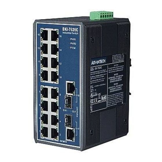
2.2 Dimensions (units: mm) Figure 2.1: Front View of EKI-7626C Chapter3... -
Page 20: Figure 2.2: Side View Of Eki-7626C
Figure 2.2: Side View of EKI-7626C EKI-7626C User Manual... -
Page 21: Figure 2.3: Rear View Of Eki-7626C
Figure 2.3: Rear View of EKI-7626C Chapter3... -
Page 22: Figure 2.4: Top View Of Eki-7626C
Figure 2.4: Top View of EKI-7626C EKI-7626C User Manual... -
Page 23: Mounting
2.3.1 Wall mounting EKI-7626C can be wall-mounted by using the included mounting kit. Then, hang on the EKI-7626C to the nails on the wall. First, use the screws included in the package to combine the EKI-7626C and metal mounting kit. And then you can install the device firmly via the components, please see Figure 2.5 as below. -
Page 24: Din-Rail Mounting
The DIN-rail kit is screwed on the industrial switch when out of factory. If the DIN-rail kit is not screwed on the industrial switch, please screw the DIN-rail kit on the switch first. First, hang the EKI-7626C to the DIN-rail with angle of inclination. See Figure 2.6. Figure 2.6: Installation to DIN-rail Step 1... -
Page 25: Figure 2.7: Installation To Din-Rail Step 2
Then, let the device down straight to slide over the rail smoothly. See Figure 2.7. Figure 2.7: Installation to DIN-rail Step 2 Chapter3... -
Page 26: Network Connection
100m long. The connection can be made from any TX port of the EKI-7626C (MDI-X) to another hub or switch either MDI-X or uplink MDI port. The EKI-7626C supports auto-crossover to make networking more easy and flexible. You can connect any RJ-45 (MDI-X) station port on the switch to any device such as a switch, bridge or router. -
Page 27: Figure 2.9: Transceiver Inserted
Figure 2.9: Transceiver Inserted Second, insert the fiber cable of LC connector into the transceiver. Figure 2.10: LC connector to the transceiver Chapter3... -
Page 28: Figure 2.11: Remove Lc Connector
First, press the upper side of the LC connector to release from the transceiver and pull it out. Figure 2.11: Remove LC connector Second, push down the metal loop and pull the transceiver out by the plastic handle. Figure 2.12: Pull out from the transceiver EKI-7626C User Manual... -
Page 29: Power Connection
2.6 Power Connection The EKI-7626C supports dual +12 ~ 48 V power inputs and power-fail relay output. Figure 2.8: Pin Assignment of the Power Connector You can connect an alarm indicator, buzzer or other signaling equipment through the relay output. The relay opens if power input 1, 2 fails or port link down/break (″Open″... - Page 30 EKI-7626C User Manual...
-
Page 31: Chapter 3 Troubleshooting
Troubleshooting... - Page 32 If user still cannot resolve the problem, contact the local dealer for assistance. If the Industrial switch LED indicators are normal and the connected cables are correct but the packets still cannot transmit, please check your system’s Ethernet devices configuration or status. EKI-7626C User Manual...
-
Page 33: Appendix A Pin Assignment & Wiring
Pin Assignment & Wiring... -
Page 34: Figure A.1: Rj-45 Pin Assignment
Appendix A Pin Assignment & Wiring It is suggested to adopt ELA/TIA as the wiring of the RJ-45. Figure A.1: RJ-45 Pin Assignment Figure A.2: EIA/TIA-568B Figure A.2: EIA/TIA-568A EKI-7626C User Manual... -
Page 35: Appendix B Compatible Sfp Modules
Compatible SFP Modules... - Page 36 Appendix B Compatible SFP Modules The table below shows compatible SFP modules for EKI-7626C. Transmission Item Brand Part Number Mode Distance AVAGO AFBR-5710PZ 550m APAC LM28-C3S-TC-N 550m Multi-mode HOATECH HTI8512-X5ATO 550m SPACE SHUTTLE S56L-S85-6L-N 550m SP-GB-LX 10km LuminentOIC SP-GB-ELX 20km...
Need help?
Do you have a question about the EKI-7626C and is the answer not in the manual?
Questions and answers