
Related Manuals for Advantech EDGE ER75i v2


Summary of Contents for Advantech EDGE ER75i v2
- Page 1 EDGE Industrial Router ER75i v2 USER MANUAL LUCOM GmbH — Flößaustr. 22a — 90763 Fürth — Tel.: +49 911/ 957 606 00 — E-Mail: info@lucom.de — www.lucom.de...
- Page 2 Website www.advantech- bb.com c 2020 Advantech Czech s.r.o. No part of this publication may be reproduced or transmitted in any form or by any means, electronic or mechanical, including photography, recording, or any information storage and retrieval system without written consent. Information in this manual is subject to change without notice, and does not represent a commitment on the part of Advantech.
- Page 3 Please see http://ep.advantech- bb.cz/devzone for more information. Advantech Czech s.r.o., Sokolska 71, 562 04 Usti nad Orlici, Czech Republic Document No. MAN- 0013- EN, revision from May 19, 2020. Released in the Czech Republic. LUCOM GmbH — Flößaustr. 22a — 90763 Fürth — Tel.: +49 911/ 957 606 00 — E-Mail: info@lucom.de — www.lucom.de...
-
Page 4: Table Of Contents
ER75i v2 Contents 1 Safety Instructions 2 WEEE directive 3 Router Description 4 Contents of Package 5 Router Design 5.1 Router versions ........5.2 Delivery identification . - Page 5 ER75i v2 7.1 Basic parameters ........7.2 Standards and regulations .
- Page 6 ER75i v2 List of Figures Contents of package ....... . . Front panel ER75i v2B .
- Page 7 ER75i v2 List of Tables Router versions ........Delivery identification .
-
Page 8: Safety Instructions
ER75i v2 1. Safety Instructions Please, observe the following instructions: The router must be used in compliance with all applicable international and national laws and in compliance with any special restrictions regulating the utilization of the router in prescribed applications and environments. To prevent possible injury and damage to appliances and to ensure compliance with all relevant provisions, use only the original accessories. -
Page 9: Weee Directive
ER75i v2 2. Product Disposal Instructions The WEEE (Waste Electrical and Electronic Equipment: 2012/19/EU) directive was in- troduced to ensure that electrical/electronic products are recycled using the best available recovery techniques in order to minimize impact on the environment. This product contains high quality materials and components which can be recycled. -
Page 10: Router Description
ER75i v2 3. Router Description EDGE industrial router ER75i v2 is used to wirelessly connect various equipments and de- vices via Ethernet interface 10/100 to the Internet or intranet. Thanks to high security level and wide coverage of GPRS/EDGE technology provided by mobile phone operators, it is mostly used in industrial applications, for remote maintenance and service of machines, or for data transfer from solar or wind power plants. -
Page 11: Contents Of Package
ER75i v2 4. Contents of Package Basic delivered set of router includes: router, power supply, crossover UTP cable, up to two external antennas, clip for the DIN rail, paper start guide. Figure 1: Contents of package Temperature range for power supply is reduced to 0 C to +40 C! As optional accessories can also be supplied the following expansion ports (one for Basic version or two for Full version): RS232, RS485/422, MBUS, ETHERNET, CNT, SWITCH, WIFI, WMBUS or SDH. -
Page 12: Router Design
ER75i v2 5. Router Design 5.1 Router versions ER75i v2 router is supplied in the following versions (see table below). All versions are available in plastic or metal box according to customer requirements. Router versions Router Box ER75i v2B Plastic ER75i v2B SL Metal ER75i v2F... -
Page 13: Label Examples
ER75i v2 5.2 Delivery identification Trade name Order code Description ER75i v2B BB- ER2B51v01y Basic version in the plastic box ER75i v2B SL BB- ER2B51v02y Basic version in the metal box ER75i v2F BB- ER2F51vw1y Full version in the plastic box ER75i v2F SL BB- ER2F51vw2y Full version in the metal box... -
Page 14: Type Of Port #1
ER75i v2 5.3 Order codes 5.3.1 Order code structure Order code for basic version has following structure: BB- ER2B51v0xy , where: v = port #1, x = type of router box, y = type of power supply. Order code for full version has following structure: BB- ER2F51vwxy , where: v = port #1,... -
Page 15: Type Of Port #2
ER75i v2 Letter "w" – port #2 Port type Letter "w" in code none RS232 RS485 RS422 MBUS WiFi WMBUS Table 4: Type of port #2 Letter "x" – type of the router box Type of router box Letter "x" in code Plastic Metal Table 5: Type of router box... -
Page 16: Order Code Examples
ER75i v2 5.3.2 Order code examples Examples of order codes are listed in the table bellow: Order code Features – interfaces Power supply BB- ER2B510010 EDGE module – 1x SIM reader, plastic none 1x ETH, 1x USB, 1x I/O, BB- ER2B511021 EDGE module –... -
Page 17: Basic Dimensions Of Plastic Box (Bottom And Front View)
ER75i v2 5.4 Basic dimensions of the router box 5.4.1 Plastic box Figure 9: Basic dimensions of plastic box (bottom and front view) 5.4.2 Metal box Figure 10: Basic dimensions of metal box (bottom and front view) LUCOM GmbH — Flößaustr. 22a — 90763 Fürth — Tel.: +49 911/ 957 606 00 — E-Mail: info@lucom.de — www.lucom.de... -
Page 18: Space Around Antennas (Plastic)
ER75i v2 5.5 Mounting recommendations possibility to be put on a work surface, DIN rail EN 60715 with included plastic or metal clip. For the most of applications with a built- in router in a switch board it is possible to recognize two kinds of environments: no public and industry environment of low voltage with high interference, public environment of low voltage without high interference. -
Page 19: Cable Routing (Plastic)
ER75i v2 For every cables we recommend to bind the bunch, we recommend for this use: – Length of the bunch (combination of power supply and data cables) can be maxi- mum 1.5 m. If the length of data cables exceeds 1.5 m or in the event of, the cable leads towards the switch –... -
Page 20: Default Position Of Plastic And Metal Din Rail Clip
ER75i v2 5.6 Removal from the DIN rail The DIN rail clip is suitable for a DIN rail according to EN 60715 standard only. The default position of plastic or metal rail clip, which is used for mounting the router on a DIN rail, is shown in the following figure. -
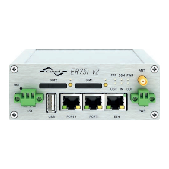
Page 21: Front Panel Er75I V2F
ER75i v2 5.7 Description of the front panel On the front panel is the following: Caption Connector Description 2- pin Connector for the power supply. RJ45 Connector for connection into the local computer network. PORT1 RJ45 Connector for expansion port RS232, RS458/422, MBUS, ETHERNET, CNT or SWITCH. -
Page 22: Status Indication
ER75i v2 5.7.1 Status indication About router status inform eight LED indicators on the front panel. ETH port, PORT1 and PORT2 have two additional LEDs that provide information about port status. Caption Color State Description Green Blinking Router is ready Starting of the router Fast blinking Updating firmware... -
Page 23: Power Connector
ER75i v2 5.7.2 Power connector PWR Panel socket 2- pin. Pin number Signal mark Description VCC(+) Positive pole of DC supply voltage (+9 to +36 V DC) GND(- ) Negative pole of DC supply voltage Table 10: Connection of power connector Figure 20: Power connector Power supply for router is required between +9 V to +36 V DC supply. -
Page 24: Connecting Of The Antenna
ER75i v2 5.7.3 Antenna connector ANT (and AUX) Main antenna is connected to the router using the SMA connector on the front panel. If WIFI or WMBUS expansion port is equipped on customer’s request, the second SMA antenna connector is also available on the front panel. Through this connector can be connected the additional antenna (it is reverse connector R- SMA in case of the WIFI expansion port). -
Page 25: Ejected Sim Holder
ER75i v2 5.7.4 SIM card reader The SIM card reader for 3 V and 1,8 V SIM cards is placed on the front panel of the router. For getting the router to work is necessary to insert an activated SIM card with an unblocked PIN code. -
Page 26: Ethernet Connector
ER75i v2 5.7.5 Ethernet Port ETH The panel socket RJ45 is used for this interface. The isolation barrier of the Ethernet signal ports against the ground is 1500 V. Signal mark Description Data flow direction TXD+ Transmit Data – positive pole Input/Output TXD- Transmit Data –... -
Page 27: Port1 Cable Connection
ER75i v2 5.7.6 PORT1 The PORT1 is equipped on customer’s request with one of the offered expansion ports: RS232 MBUS RS485 RS422 SWITCH (together with PORT2) ETHERNET Description and examples of expansion ports connection can be found in user’s guide for corresponding expansion port. -
Page 28: Port2 Cable Connection
ER75i v2 Plug cable for the second expansion port into the RJ45 connector labeled as PORT2 (see the figure below). Figure 27: PORT2 cable connection 5.7.8 USB Port Panel socket USB- A. Signal mark Description Data flow direction +5 V Positive pole of 5 V DC supply voltage, 0.5 A USB data - USB data signal –... -
Page 29: O Connector
ER75i v2 5.7.9 I/O Port Panel socket 3- pin. Signal mark Description Data flow direction BIN0 Binary input Input Signal ground OUT0 Binary output Output Table 13: Connection of I/O port Figure 29: I/O connector I/O user interface is designed for processing of binary input and control (setting) binary output. -
Page 30: Connection Of Input And Output To The Router
ER75i v2 Example of a circuit describing connection of binary input and output to the router: Figure 31: Connection of input and output to the router LUCOM GmbH — Flößaustr. 22a — 90763 Fürth — Tel.: +49 911/ 957 606 00 — E-Mail: info@lucom.de — www.lucom.de... -
Page 31: Router Reset
ER75i v2 5.7.10 Reset When PWR LED starts flashing on the front panel, it is possible to restore the default con- figuration of the router by pressing the RST button on the front panel. After pressing this button the default configuration is restored and then router reboots (green LED will be on). For pressing the RST button could be used a narrow screwdriver. -
Page 32: First Use
ER75i v2 6. First Use 6.1 Connecting the router before first use Before putting the router into operation it is necessary to connect all components which are required to run your applications. Don’t forget to insert SIM card. The router can not operate without connected antenna, SIM card and power supply. If the antenna is not connected, router can be damaged. -
Page 33: Entering The Ip Address Of The Router
ER75i v2 6.2 Start The router is put into operation when the power supply is connected to this router. By default, the router will automatically start to log on to the default APN. DHCP server will start to assign addresses for devices on the Ethernet port ETH0. Router’s behavior can be changed via the web interface. -
Page 34: Router Web Interface
ER75i v2 After successfully entering login information user gains access to the router via his internet browser. Figure 36: Router web interface A detailed description of the router settings via the Web interface can be found in the document Configuration manual for v2 routers. 6.3.2 Configuration over SSH or Telnet Device management can be done by accessing the device through the Secure Shell (SSH) or the Telnet protocol. -
Page 35: Technical Parameters
ER75i v2 7. Technical Parameters 7.1 Basic parameters ER75i v2 Temperature range Operating - 40 C to +70 C Storage - 40 C to +85 C Humidity Operating 0 to 95 % relative humidity non condensing Storage 0 to 95 % relative humidity non condensing Altitude Operating 2000 m / 70 kPa... -
Page 36: Technical Parameters Of Module
ER75i v2 7.3 Technical parameters of module EDGE module Frequency bands EGSM850, EGSM900, GSM1800 and GSM1900 Transmit power Class 4 (2 W) for EGSM850 Class 4 (2 W) for EGSM900 Class 1 (1 W) for GSM1800 Class 1 (1 W) for GSM1900 Table 17: Technical parameters of module 7.4 Other Technical Parameters Other technical parameters... -
Page 37: Related Documents
ER75i v2 8. Related Documents Advantech Czech: Start guide for v2 routers, Advantech Czech: Configuration manual for v2 routers, Advantech Czech: User’s manual – Expansion port RS232, Advantech Czech: User’s manual – Expansion port RS485/422, Advantech Czech: User’s manual – Expansion port MBUS, Advantech Czech: User’s manual –... -
Page 38: Troubleshooting
ER75i v2 9. Troubleshooting If you cannot connect to the router from your PC, your network card may be configured in such a way that it is not possible to connect to the router. Take one or more of the following steps in order to solve the problem: Make sure your PC’s network card is configured to obtain the IP address form the DHCP server (by default the DHCP server is running in the router). - Page 39 ER75i v2 In a private APN it is not recommended to get the DNS settings from operator (on "Mobile WAN" page) Go to "System Log" page in "Status" section and observe where the error occurs. I cannot connect from the Internet to the device behind the router. I have NAT enabled.
- Page 40 ER75i v2 Serial communication is not working. Verify that the router model supports serial communications. Also verify the serial communication settings. To do so, open the router’s configuration menu via the web browser, select the appropriate "Expansion Port" from "Configuration" part of the menu and verify the settings.
-
Page 41: Customers Support
During cleaning of the router do not use aggressive chemicals, solvents and abrasive cleaners! Hereby, Advantech Czech s.r.o. company declares that the radio equipment narrated in this user’s guide is in compliance with EU Directive 2014/53/EU. The full text of the EU Declaration of Conformity is available at the following internet address: www.advantech- bb.cz/eudoc...
Need help?
Do you have a question about the EDGE ER75i v2 and is the answer not in the manual?
Questions and answers