Table of Contents
Advertisement
Advertisement
Table of Contents

Subscribe to Our Youtube Channel
Related Manuals for Advantech EDG-6528


Summary of Contents for Advantech EDG-6528
-
Page 1: User Manual
EDG-6528 8-Port Industrial 10/100 Mbps Ethernet Switch User Manual... - Page 2 No part of this man- ual may be reproduced, copied, translated or transmitted in any form or by any means without the prior written permission of Advantech Co., Ltd. Information provided in this manual is intended to be accurate and reli- able.
- Page 3 Product Warranty (2 years) Advantech warrants to you, the original purchaser, that each of its prod- ucts will be free from defects in materials and workmanship for two years from the date of purchase. This warranty does not apply to any products which have been repaired or...
- Page 4 Step 1. Visit the Advantech web site at www.advantech.com/support where you can find the latest information about the product. Step 2. Contact your distributor, sales representative, or Advantech's cus- tomer service center for technical support if you need additional assistance. Please have the following information ready before...
-
Page 5: Table Of Contents
Chapter 2 Installation ............8 LED Definitions ..............8 Table 2.1:EDG-6528 LED Definition ......8 Dimensions................ 9 Figure 2.1:EDG-6528 Front Panel and Dimension ..9 Mounting ................. 10 2.3.1 Panel Mounting ............10 Figure 2.2:Attaching the Bracket ......... 10 Figure 2.3:Panel Mounting .......... 10 2.3.2... - Page 6 EDG-6528 User Manual...
-
Page 7: Chapter 1 Introduction
Introduction Sections include: • Features • Specifications • Packing List • Ordering Information • Safety Precaution... - Page 8 If there is a power failure, EDG-6528 will automatically switch to the secondary power input. Flexible Mounting EDG-6528 is extremely compact and can be mounted on a DIN-rail or a panel, so it is suitable for any space-constrained environment. Advanced Protection for Power line and Ethernet Port...
-
Page 9: Feature Summary
Wide Operating Temperature Range The operating temperature of the EDG-6528 is between 0 and 70° C, and the EDG-6528I can operate between -40 and 85° C. With such a wide range you can use the EDG-6528 in some of the harshest industrial envi- ronments that exist. -
Page 10: Specifications
LED Indicators Power, Fault, Link, 10/100 Mbps Power Power Connectors 5-pin removable screw terminal Power Consumption Max.3.1 W Power Input EDG-6528/6528I: 2 x Unregulated 12~48 V EDG-6528L: 1 x Unregualted 12~48 V Fault Output Present Mechanism Dimensions (WxHxD) 56x134x114 mm Enclosure... - Page 11 EN55024 IEC61000-4-2/3/4/5/6/8/11 Ingress Protection IP30 Environment Operating Humidity 20 ~ 95% (non-condensing) Operating EDG-6528/6528L: 0~70° C (32~158° F) Temperature EDG-6528I: -40~85° C (-40~185° F) Storage Humidity 0 ~ 95% (non-condensing) Storage EDG-6528/6528L: -10~80° C (14~176° F) Temperature EDG-6528I: -50~95° C (-58~203° F)
-
Page 12: Packing List
• INET CD-ROM • DIN-rail mounting kit • Panel mounting bracket 1.5 Ordering Information • EDG-6528 8-port Industrial 10/100 Mbps Ethernet Switch • EDG-6528L 8-port Industrial 10/100 Mbps Unmanaged Ethernet Switch • EDG-6528I 8-port Industrial 10/100 Mbps Ethernet Switch with Wide Operating Temperature 1.6 Safety Precaution... -
Page 13: Chapter 2 Installation
Installation In this chapter, you will be given an overview of the EDG-6528 installation procedure. Sections include: • LED Definitions • Dimensions • Mounting • Network Connections • Power Connections... -
Page 14: Table 2.1:Edg-6528 Led Definition
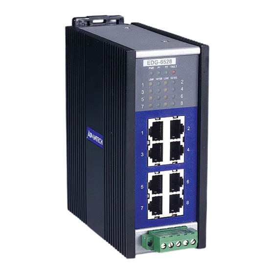
Chapter 2 Installation 2.1 LED Definitions There are network status LEDs located on the front panel of EDG-6528, each with its own specific meaning.. Table 2.1: EDG-6528 LED Definition Color Description Green Power is on Power is off Green Power input 1 is active... -
Page 15: Dimensions
2.2 Dimensions Figure 2.1: EDG-6528 Front Panel and Dimension Chapter 2... -
Page 16: Mounting
2.3 Mounting 2.3.1 Panel Mounting • Attach the bracket to the EDG-6528 with four screws. • Place the EDG-6528 against the panel or wall, and fasten it by using two screws in the bracket’s holes. Figure 2.2: Attaching the Bracket Figure 2.3: Panel Mounting... -
Page 17: Din-Rail Mounting
2.3.2 DIN-rail Mounting Attach the DIN-rail mounting kit to the EDG-6528 with six screws. Figure 2.4: Attaching the DIN-rail Mounting Kit Snap the EDG-6528 onto the DIN rail to attach it. Figure 2.5: DIN-rail Mounting. Chapter 2... -
Page 18: Din-Rail Dismounting
2.3.3 DIN-rail Dismounting Use a flat screwdriver to lift the DIN rail’s attachment bracket up. This will release the EDG-6528 from the Din-rail. Then pull the EDG-6528 down to dismount it. Figure 2.6: DIN-rail Dismounting EDG-6528 User Manual... -
Page 19: Network Connections
2.4.2 Connection to Other Hubs or Switches EDG-6528 has 8 RJ-45 ports that support connection to 10 Mbps Ether- net or 100 Mbps Fast Ethernet, and half or fullduplex operation. EDG- 6528 can be connected to other hubs or switches via a two-pair straight through cable or a crossover cable. -
Page 20: Power Connections
2.5 Power Connections EDG-6528 and EDG-6528I support two individual power inputs (P1/P2); it will switch to another power input if one power input fails. Description Power input 1 (Range: +12~48VDC) +Vs* Power input 2 (Range: +12~48VDC) Power ground Relay out (EDG-6528L does not have this function) You can connect to an alarm such as an indicator, buzzer or other signaling equipment by EDG-6528’s relay output.
Need help?
Do you have a question about the EDG-6528 and is the answer not in the manual?
Questions and answers