Chapters
Table of Contents

Related Manuals for Johnson Controls YORK YK Style G OPTIVIEW


Summary of Contents for Johnson Controls YORK YK Style G OPTIVIEW
- Page 1 CENTRIFUGAL LIQUID CHILLERS OPERATIONS AND MAINTENANCE Supersedes: 160.75-O1 (508) Form 160.75-O1 (211) MODEL YK (STYLE G) R-134a WITH OPTIVIEW CONTROL CENTER FOR ELECTRO-MECHANICAL STARTER, SOLID STATE STARTER AND VARIABLE SPEED DRIVE LD15222...
- Page 2 All wiring must be in accordance with Johnson Controls’ published specifications and must be performed only by a qualified electrician. Johnson Controls will NOT be responsible for damage/problems resulting from improper connections to the controls or application of improper control signals.
- Page 3 FORM 160.75-O1 (211) CHANGEABILITY OF THIS DOCUMENT In complying with Johnson Controls’ policy for contin- Operating/service personnel maintains the responsi- uous product improvement, the information contained bility of the applicability of these documents to the in this document is subject to change without notice.
- Page 4 FORM 160.75-O1 (211) NOMENCLATURE – STYLE (Design Level) MOTOR CODE POWER SUPPLY – for 60 Hz 5 for 50 Hz COMPRESSOR CODE* CONDENSER CODE* EVAPORATOR CODE* * Refer to YK Engineering Guide for (Form 160.75-EG1) Shell/Motor/Compressor combinations. MODEL* JOHNSON CONTROLS...
-
Page 5: Table Of Contents
Checking System For Leaks .......................... 27 Conducting R-22 Pressure Test........................27 Vacuum Testing .............................. 28 Vacuum Dehydration ............................29 Operation ................................ 29 Refrigerant Charging ............................29 Checking The Refrigerant Charge During Unit Shutdown ................30 Handling Refrigerant For Dismantling And Repairs ..................30 JOHNSON CONTROLS... - Page 6 FIGURE 16 - Diagram, Megging Motor Windings ....................30 FIGURE 17 - Motor Starter Temperature And Insulation Resistances ..............31 LIST OF TABLES TABLE 1 - Operation Analysis Chart ........................25 TABLE 2 - System Pressures ..........................28 TABLE 3 - Bearing Lubrication ..........................35 JOHNSON CONTROLS...
-
Page 7: Section 1 - Description Of System And Fundamentals Of Operation
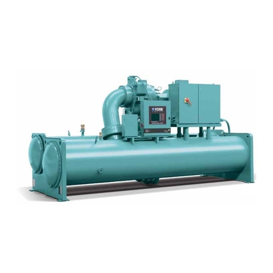
The warmed liquid is then returned to time, weekends, and holidays. The operating status, the chiller to complete the chilled liquid circuit. temperatures, pressures, and other information perti- COMPRESSOR CONTROL CENTER MOTOR CONDENSER LD15222 EVAPORATOR FIGURE 1 - MODEL YK CHILLER JOHNSON CONTROLS... -
Page 8: Capacity Control
Wa- open to minimum load with vanes completely closed. ter flowing through the condenser tubes absorbs heat JOHNSON CONTROLS... -
Page 9: Figure 3 - Refrigerant Flow-Thru Chiller (Falling Film Evaporator)
BYPASS LINE DISCHARGE LIQUID LEVEL OPTIONAL VALVE ISOLATION VALVE EVAPORATOR CONDENSER SUCTION BAFFLE LIQUID LEVEL LIQUID LEVEL SUB-COOLER OPTIONAL ISOLATION LD00924A VALVE Rev. 2 (10-11-2010) FIGURE 3 - REFRIGERANT FLOW-THRU CHILLER (FALLING FILM EVAPORATOR) Dan Sowers dan.sowers-ext@jci.com (717) 771-7535 JOHNSON CONTROLS... -
Page 10: Figure 4 - Refrigerant Flow-Thru Chiller (Flooded Evaporator)
OPTIONAL ISOLATION MESH ELIMINATORS or VALVE SUCTION BAFFLE EVAPORATOR CONDENSER LIQUID LEVEL LIQUID LEVEL SUB-COOLER OPTIONAL LIQUID LEVEL ISOLATION VALVE LD00924B VALVE Rev. 2 (12-09-2010) Dan Sowers dan.sowers-ext@jci.com FIGURE 4 - REFRIGERANT FLOW-THRU CHILLER (FLOODED EVAPORATOR) (717) 771-7535 JOHNSON CONTROLS... -
Page 11: Section 2 - System Operating Procedures
START side of the switch to start the chill- er.) When the start switch is energized, the Con- LD08647 trol Center is placed in an operating mode and FIGURE 5 - OIL LEVEL INDICATOR any malfunction will be noted by messages on a graphic display. JOHNSON CONTROLS... -
Page 12: Figure 6 - Chiller Starting Sequence And Shutdown Sequence (Em Starter And Solid State Starter)
FIGURE 6 - CHILLER STARTING SEQUENCE AND SHUTDOWN SEQUENCE (EM STARTER AND SOLID STATE STARTER) LD15610 ** Not for all shutdowns. Refer to “Display Messages” in manual Optiview™ Control Center – Operation and Maintenance (Form 160.54-O1). FIGURE 7 - CHILLER STARTING SEQUENCE AND SHUTDOWN SEQUENCE (VARIABLE SPEED DRIVE) JOHNSON CONTROLS... -
Page 13: Chiller Operation
Figure 8 on Page 14 shows a log sheet used by liquid temperature rises, the actuator will open the Pre- Johnson Controls Personnel for recording test data on rotation Vanes to increase the capacity of the chiller. chiller systems. It is available from the factory in pads of 50 sheets each under Form 160.44-F7 and may be... -
Page 14: Figure 8 - Liquid Chiller Log Sheets
LD00467 23889A *NOTE: These items can be printed by an electronic printer connected to the Microboard and pressing the PRINT key on the Keypad, or automatically using the Data Logger feature. FIGURE 8 - LIQUID CHILLER LOG SHEETS JOHNSON CONTROLS... -
Page 15: Need For Maintenance Or Service
If Solid State Starter equipped drain liquid from hinder the performance of the unit, please call the near- starter cooling loop.) est Johnson Controls District Office. Failure to report constant troubles could damage the unit and increase 3. If freezing temperatures are encountered for peri- the cost of repairs. - Page 16 SECTION 2 - SYSTEM OPERATING PROCEDURES FORM 160.75-O1 (211) THIS PAGE INTENTIONALLY LEFT BLANK JOHNSON CONTROLS...
-
Page 17: Section 3 - System Components Description
On shutdown of the system for any reason, the oil A. Shaft seal. pump operates and continues to run for 150 seconds. The system cannot restart during that time interval. B. Front and rear journal bearings – one on each side of driving gear. JOHNSON CONTROLS... -
Page 18: Figure 9 - System Components Front View
SECTION 3 - SYSTEM COMPONENTS DESCRIPTION FORM 160.75-O1 (211) OPTIVIEW CONTROL CENTER COMPRESSOR SUCTION RELIEF VARIABLE VALVES SPEED DRIVE EVAPORATOR LD15222 VARIABLE SPEED SIGHT OIL PUMP GLASS CONTROL BOX FRONT VIEW FIGURE 9 - SYSTEM COMPONENTS FRONT VIEW JOHNSON CONTROLS... -
Page 19: Figure 10 - System Components Rear View
FORM 160.75-O1 (211) SECTION 3 - SYSTEM COMPONENTS DESCRIPTION MOTOR COMPRESSOR DISCHARGE LINE LD15223 LIQUID LINE CONDENSER OIL PUMP HOUSING REAR VIEW FIGURE 10 - SYSTEM COMPONENTS REAR VIEW JOHNSON CONTROLS... -
Page 20: Figure 11 - Schematic Drawing - (Yk) Compressor Lubrication System
COVER REFRIG. SIGHT GLASSES THERMISTOR COOLER HEATER LOW OIL PRESSURE ANGLE DRAIN VALVE TRANSDUCER SUBMERSIBLE OIL TEMP. SUMP PUMP OIL PUMP CONTROL SUCTION WITH 3-PHASE MOTOR FILTER LD15200 FIGURE 11 - SCHEMATIC DRAWING – (YK) COMPRESSOR LUBRICATION SYSTEM JOHNSON CONTROLS... -
Page 21: Oil Heater
Plugged 3/4" (19 mm) drain and vent Evaporator codes A* to K* utilize a hybrid falling film connections are provided in each waterbox. design. It contains a balance of flooded and falling film technology to optimize efficiency, minimize refriger- JOHNSON CONTROLS... -
Page 22: Refrigerant Flow Control
Isolation of the refrigerant in this system to it by sensors located throughout the chiller. must be performed by a qualified service technician. JOHNSON CONTROLS... -
Page 23: Section 4 - Operational Maintenance
5. Open all the dehydrator stop valves. COMPRESSOR SOLENOID VALVE CHECK VALVE OIL EDUCTOR BLOCK SOLENOID VALVE DEHYDRATOR STOP VALVE STOP VALVE LD08578 FIGURE 12 - OIL RETURN SYSTEM JOHNSON CONTROLS... -
Page 24: The Oil Charge
RANGE of the oil level indicator label. the pump discharge connection to the oil charg- LD08579 LD08648 OIL CHARGING VALVE FIGURE 13 - CHARGING OIL RESERVOIR WITH OIL JOHNSON CONTROLS... -
Page 25: Section 5 - Troubleshooting
5. SYMPTOM: UNUSUALLY HIGH OIL PRESSURE DEVELOPS WHEN OIL PUMP RUNS Unusually high oil pressure is dis- played when the oil pressure display High oil pressure. Transducer defec- Replace low or high oil pressure trans- key is pressed when the oil pump is tive. ducer. running. JOHNSON CONTROLS... - Page 26 Remove dirt using solvent and replace. 10. SYMPTOM: OIL PUMP FAILS TO DELIVER OIL PRESSURE No oil pressure registers when pressing Faulty oil pressure transducer. OIL PRESSURE display key when oil Replace oil pressure transducer. Faulty wiring/connectors. pump runs. JOHNSON CONTROLS...
-
Page 27: Section 6 - Maintenance
R-22 mixed with dry nitrogen so that a ha- lide torch or electronic leak detector can be used to de- tect any leaks too small to be found by the soap test. EVACUATION AND DEHYDRATION OF UNIT 27385A(D) LD00949 FIGURE 14 - EVACUATION OF CHILLER JOHNSON CONTROLS... -
Page 28: Vacuum Testing
7. If the vacuum does not hold for 8 hours within the shells. If a source of hot water is not readily avail- limits specified in Step 6 above, the leak must be able, a portable water heater should be employed. found and repaired. JOHNSON CONTROLS... -
Page 29: Vacuum Dehydration
When this final vaporization has only refrigerant vapor from the top of the drum or cyl- JOHNSON CONTROLS... -
Page 30: Checking The Refrigerant Charge During Unit Shutdown
Charge the correct amount of refrigerant and record the ambient temperature after 24 hours of level in the evaporator sight glass. idle standby. The refrigerant charge should always be checked and trimmed when the system is shut down. LD00475 FIGURE 16 - DIAGRAM, MEGGING MOTOR WINDINGS JOHNSON CONTROLS... -
Page 31: Figure 17 - Motor Starter Temperature And Insulation Resistances
FORM 160.75-O1 (211) SECTION 6 - MAINTENANCE LD00476 TEMPERATURE – °F FIGURE 17 - MOTOR STARTER TEMPERATURE AND INSULATION RESISTANCES JOHNSON CONTROLS... - Page 32 These symptoms may also be due to foul gas buildup. Purging will re- move the foul gas revealing the effect of fouling. JOHNSON CONTROLS...
-
Page 33: Compressor
Do not use carbon tetrachloride for this pump, and observing the operation of the compressor. purpose since its fumes give the same flame discoloration that the refrigerant does. JOHNSON CONTROLS... -
Page 34: Electrical Controls
If the unit is shutting down on (HOT) High Oil the nearest Johnson Controls office to request the pres- Temperature or Low Oil Pressure (OP), change the oil ence of a Johnson Controls Service Technician. -
Page 35: Section 7 - Preventive Maintenance
If alumi- num particles are found this should be brought Recommended greases for standard applications: to the attention of the nearest Johnson Controls office for their further investigation and recom- OPERATING AMBIENT TEMP. -30ºC to 50ºC mendations. -
Page 36: Leak Testing
1. The condenser tubes should be cleaned annually (operation and safety) not be changed. If the set- or earlier if conditions warrant. If the temperature tings are changed without Johnson Controls ap- difference between the water off the condenser proval, the warranty will be jeopardized. - Page 37 FORM 160.75-O1 (211) JOHNSON CONTROLS...
- Page 38 FORM 160.75-O1 (111) NOTES JOHNSON CONTROLS...
- Page 39 (°C), subtract 32° and multiply by 5/9 or 0.5556. Example: (45.0°F - 32°) x 0.5556 = 27.2°C To convert a temperature range (i.e., a range of 10°F) from Fahrenheit to Celsius, multiply by 5/9 or 0.5556. Example: 10.0°F range x 0.5556 = 5.6 °C range JOHNSON CONTROLS...
- Page 40 Tele. 800-861-1001 P.O. Box 1592, York, Pennsylvania USA 17405-1592 Subject to change without notice. Printed in USA www.york.com Copyright © by Johnson Controls 2011 ALL RIGHTS RESERVED Form 160.75-O1 (211) Supersedes: 160.75-O1 (309)
- Page 41 OPTIVIEW™ CONTROL CENTER CENTRIFUGAL LIQUID CHILLERS OPERATION MANUAL Supersedes: 160.54-O1 (1013) Form 160.54-O1 (914) MODEL YK (THROUGH STYLE G) R-134a COOLING ONLY WITH OPTIVIEW™ CONTROL CENTER FOR ELECTRO-MECHANICAL STARTER, SOLID STATE STARTER AND VARIABLE SPEED DRIVE LD15222 Issue Date: September 10, 2014...
- Page 42 All wiring must be in accordance with Johnson Controls’ published specifications and must be performed only by a qualified electrician. Johnson Controls will NOT be responsible for damage/problems resulting from improper connections to the controls or application of improper control signals.
- Page 43 FORM 160.54-O1 ISSUE DATE: 9/10/2014 CHANGEABILITY OF THIS DOCUMENT In complying with Johnson Controls’ policy for con- these documents, the technician should verify whether tinuous product improvement, the information con- the equipment has been modified and if current litera- tained in this document is subject to change without ture is available from the owner of the equipment prior notice.
- Page 44 FORM 160.54-O1 ISSUE DATE: 9/10/2014 NOMENCLATURE – STYLE (Design Level) MOTOR CODE POWER SUPPLY – for 60Hz 5 for 50Hz COMPRESSOR CODE* CONDENSER CODE* EVAPORATOR CODE* * Refer to YK Engineering Guide (Form 160.75-EG1) for Shell/Motor/Compressor combinations. MODEL* JOHNSON CONTROLS...
- Page 45 Harmonic Filter Details Screen ........................113 Motor Lubrication Screen ..........................115 Motor Details Screen ............................ 119 Motor Setpoints Screen ..........................123 Setpoints Screen ............................127 Setup Screen ..............................131 Quick Start Screen ............................137 Schedule Screen ............................141 User Screen ..............................143 JOHNSON CONTROLS...
- Page 46 Compressor Motor Variable Speed Drive: Safety Shutdown Messages ............199 SECTION 4 - PRINTING ............................203 Printing Overview ............................203 Acceptable Printers ............................204 Printer Connections ............................204 Printer Setup ..............................205 Control Center Setup ............................ 205 Downloading System Prints to a Laptop ...................... 205 JOHNSON CONTROLS...
- Page 47 Part Number 371-03789-XXX (503hp 60Hz; 419hp 50Hz) ............. 113 FIGURE 40 - Motor Lubrication Screen......................... 115 FIGURE 41 - Motor Details Screen (Software Version C.Opt.01.22.307 and Later) ..........119 FIGURE 42 - Motor Setpoints Screen (Software Version C.Opt.01.22.307 and Later) ......... 123 JOHNSON CONTROLS...
- Page 48 TABLE 3 - Condenser Temperature Range ......................134 TABLE 4 - Master Slot Numbers List for Use with Trend Feature .................172 TABLE 5 - OKIDATA OKIPOS 441 ........................204 TABLE 6 - Brecknell CP130 ..........................207 TABLE 7 - SI Metric Conversion ...........................219 JOHNSON CONTROLS...
-
Page 49: Section 1 - Description Of System And Fundamentals Of Operation
Logic Board that is installed inside of tures, pressures, and other information pertinent to oper- the Control Center. ation of the chiller are automatically displayed and read COMPRESSOR CONTROL CENTER MOTOR CONDENSER LD15222 EVAPORATOR FIGURE 1 - MODEL YK CHILLER JOHNSON CONTROLS... -
Page 50: Capacity Control
The warmed liquid is then returned to the chiller to complete the chilled liquid circuit. JOHNSON CONTROLS... - Page 51 OPTIONAL HOT GAS BYPASS LINE DISCHARGE LIQUID LEVEL OPTIONAL VALVE ISOLATION VALVE EVAPORATOR CONDENSER SUCTION BAFFLE LIQUID LEVEL LIQUID LEVEL SUB-COOLER LD00924A OPTIONAL ISOLATION VALVE FIGURE 3 - REFRIGERANT FLOW-THRU CHILLER Rev. 2 (10-11-2010) Dan Sowers dan.sowers-ext@jci.com (717) 771-7535 JOHNSON CONTROLS...
- Page 52 FORM 160.54-O1 SECTION 1 - DESCRIPTION OF SYSTEM AND FUNDAMENTALSOF OPERATION ISSUE DATE: 9/10/2014 THIS PAGE INTENTIONALLY LEFT BLANK JOHNSON CONTROLS...
-
Page 53: Section 2 - Optiview Control Center Introduction
Service Technician use only. They are 6. Safety Shutdown Contacts only displayed when logged in at SERVICE access lev- el or higher. The setpoints and parameters displayed on 7. Cycling Shutdown Contacts these screens are explained in detail in OptiView Con- JOHNSON CONTROLS... - Page 54 (or later). Software upgrades should only be performed by a Ser- The upgrade includes a larger BRAM (U38) and vice Technician. an additional RS-485 port on COM2 serial port for Modbus communications. When used in larger JOHNSON CONTROLS...
-
Page 55: Optiview Control Center
This guarantees In order to reject entry of a setpoint or dis- that manual intervention has taken place and the miss an entry form, the ‘X’ key is provided as shutdown has been acknowledged. a universal ‘Cancel’ symbol. JOHNSON CONTROLS... - Page 56 ‘<’ symbol. In some cases, the value may be ren- dered invalid by other conditions and the display will the chiller and other devices connected to the chiller use X’s to indicate this. system. Setpoints can fall into several categories. They JOHNSON CONTROLS...
- Page 57 The system will immediately refresh the display with the graphics for that screen. Following is a layout of all the screens and how they are connected. JOHNSON CONTROLS...
- Page 58 Setpoints (Page 127) Setup (Page 131) Schedule (Page 141) User (Page 143) Comms (Page 145) Printer (Page 147) Sales Order (Page 149) Operations (Page 151) Diagnostics (Refer to OptiView Control Center - Service Instructions (Form 160.54-M1)) Quick Start (Page 137) JOHNSON CONTROLS...
- Page 59 *Saturation temperatures are calculated values. They will display XXX if the pressure used for the calculation is out of range. **Not applicable to chillers equipped with Flash Memory Card version C.MLM.01.03 and later. ***7.5 PSIG Flash Memory Card version C.MLM.01.04 and later. JOHNSON CONTROLS...
- Page 60 FORM 160.54-O1 SECTION 2 - OPTIVIEW CONTROL CENTER INTRODUCTION ISSUE DATE: 9/10/2014 THIS PAGE INTENTIONALLY LEFT BLANK JOHNSON CONTROLS...
-
Page 61: Home Screen
Displays the temperature of the liquid as it leaves the heating condenser tube bundle. Only appears when the Condenser Liquid Temperature – Return Heat Recovery is enabled. Displays the temperature of the liquid as it enters the condenser. JOHNSON CONTROLS... - Page 62 (VMS) closes, indicating the vanes have fully closed after making necessary setpoint adjustments the user (or 3.5 minutes have elapsed, whichever occurs first), return to the HOME Screen and logout. the Run signal is removed from the compressor motor JOHNSON CONTROLS...
- Page 63 10 shutdown conditions. Compressor A detailed view of all the compressor parameters. This includes Pre-rotation Vane control, Hot Gas Bypass Control, Proximity Probe Calibration, and PRV Calibra- tion. JOHNSON CONTROLS...
- Page 64 FORM 160.54-O1 SECTION 2 - OPTIVIEW CONTROL CENTER INTRODUCTION ISSUE DATE: 9/10/2014 THIS PAGE INTENTIONALLY LEFT BLANK JOHNSON CONTROLS...
-
Page 65: System Screen
Displays the temperature of the refrigerant in its gas- Chilled Liquid Temperature – Setpoint eous state at discharge of the compressor as it travels Displays the active temperature setpoint to which the to the condenser. chiller is controlling the evaporator liquid. This value JOHNSON CONTROLS... - Page 66 Displays the Hot Water Setpoint to which the Leaving Heating Condenser Liquid Temperature is being con- NAVIGATION trolled. Only appears when Heat Recovery is enabled Home and Hot Water Control is enabled. Access Level Required: VIEW Returns user to HOME Screen. JOHNSON CONTROLS...
-
Page 67: Evaporator Screen
Displays the present refrigerant pressure in the evapo- Leaving Chilled Liquid Temperature Setpoints rator. – Setpoint Displays the present setpoint to which the chiller is op- Evaporator Saturation Temperature erating, whether controlled locally or remotely. Displays the present saturation temperature in the evaporator. JOHNSON CONTROLS... - Page 68 Usually, the Offset used setpoint is programmed for 10°F and the operator pro- is the same as the value programmed for the Shutdown grammed value is 45°F, then the remote device can set JOHNSON CONTROLS...
- Page 69 Brine Low Evaporator Cutout Access Level Required: SERVICE This value is only available in Brine mode. It allows the user to specify the Evaporator Pressure at which a safety shutdown is initiated. JOHNSON CONTROLS...
- Page 70 FORM 160.54-O1 SECTION 2 - OPTIVIEW CONTROL CENTER INTRODUCTION ISSUE DATE: 9/10/2014 THIS PAGE INTENTIONALLY LEFT BLANK JOHNSON CONTROLS...
-
Page 71: Condenser Screen
Displays the difference between the Condenser Refrig- erant temperature and the Leaving Condenser Liquid Leaving Condenser Liquid Temperature temperature. The Condenser Refrigerant temperature Displays the water temperature as it leaves the con- will be represented by the Condenser Saturation tem- denser. perature. JOHNSON CONTROLS... - Page 72 When Heat Pump Duty is set to enabled, this setpoint will be represented by the Condenser Saturation tem- is automatically set to 193 PSIG. perature. If the Drop Leg Sensor is not present, this temperature is not displayed. JOHNSON CONTROLS...
- Page 73 Heat Pump Setpoints and parameters. Only appears when Heat Pump is enabled on the SET- Refrigerant Level Control UP Screen. Access Level Required: SERVICE Moves to the subscreen allowing programming of the refrigerant liquid level control setpoints. JOHNSON CONTROLS...
- Page 74 FORM 160.54-O1 SECTION 2 - OPTIVIEW CONTROL CENTER INTRODUCTION ISSUE DATE: 9/10/2014 THIS PAGE INTENTIONALLY LEFT BLANK JOHNSON CONTROLS...
-
Page 75: Heat Recovery Screen
Displays the temperature of the liquid as it enters the When Heat recovery is enabled, the condenser flow heating condenser tube bundle. animation will show flow when either the Condenser Liquid Flow Switch or the Heating Condenser Liquid Flow Switch says flow is present. When Heat Recov- JOHNSON CONTROLS... - Page 76 Control for Heat Recovery or it is performing Head when Hot Water Control is enabled. Pressure Control. It will not be performing control for both features at the same time. Normally, it will be performing Hot Water Control unless certain operat- JOHNSON CONTROLS...
- Page 77 Head Pressure Control is enabled. Sets the Derivative Gain of the Head Pressure Con- trol (0.00 to 5.00; default 0.00). Use the CHANGE SETPOINTS key as described above to select/enter this setpoint. Only appears when Head Pressure Con- trol is enabled. JOHNSON CONTROLS...
- Page 78 FORM 160.54-O1 SECTION 2 - OPTIVIEW CONTROL CENTER INTRODUCTION ISSUE DATE: 9/10/2014 NAVIGATION Home Returns user to HOME Screen. Condenser Returns user to CONDENSER Screen. JOHNSON CONTROLS...
-
Page 79: Head Pressure Control Screen
Control Center - Service Instructions depends on whether the PID OUTPUT Setpoint is set (Form 160.54-M1) for operation instruc- to direct or reverse. If set to direct, the 0.0% output will tions and explanation of all programmable setpoints and displayed values. JOHNSON CONTROLS... - Page 80 (0.0% to 100%; default 0.0%) Allows the Control Returns user to HOME Screen. Valve to be manually set to a pre-determined position between 0.0% and 100%. Condenser Control Valve Output Settings – Auto Returns user to CONDENSER Screen. Places the Control Valve in automatic control. JOHNSON CONTROLS...
-
Page 81: Heat Pump Screen
Displays the temperature range over which a remote speed (50Hz or 60Hz) at all times in Heating mode. In device (in Analog or Digital Remote mode) can reset Cooling mode, it operates normally. the Heat Pump Leaving Condenser Liquid Tempera- JOHNSON CONTROLS... - Page 82 10, 20, 30 or 40ºF (default 10). This number is sub- the PRV response to changes in the Leaving Condenser tracted from the local setpoint to create a range over Liquid Temperature as its being controlled in Heating JOHNSON CONTROLS...
- Page 83 Access Level Required: VIEW This is done by defining an offset below the Leaving Returns user to EVAPORATOR Screen Condenser Liquid Temperature Setpoint. It is program- mable over a range of 0 to 67°F (default 0) below the JOHNSON CONTROLS...
- Page 84 FORM 160.54-O1 SECTION 2 - OPTIVIEW CONTROL CENTER INTRODUCTION ISSUE DATE: 9/10/2014 THIS PAGE INTENTIONALLY LEFT BLANK JOHNSON CONTROLS...
-
Page 85: Refrigerant Level Control Screen
Displays the setpoint to which the refrigerant level is condenser. When the actual level is 0% to 15%, the being controlled. level is shown about 50% full. When the actual level is 16% to 31%, the level is shown about 60% full. When JOHNSON CONTROLS... - Page 86 [Refrigerant Level Control] Rate Limit Close This key establishes the response to the rate of change, the amount of change in the level within the Level Control Period is compared to the Rate Limit Close (if level less than setpoint). JOHNSON CONTROLS...
- Page 87 Is ON when the output controlling the Level Lower DISPLAY ONLY contact is on. Refrigerant Level Position Displays the present position of the liquid level. The refrigerant level is animated in the cutaway view of the condenser. When the actual level is 0% to 15%, the JOHNSON CONTROLS...
- Page 88 Refrigerant Level Setpoint over a period of Access Level Required: SERVICE time programmed as the Ramp-Up Time Setpoint (3 to Moves to a subscreen allowing programming of the 15 minutes; default 8). Refrigerant Level Control Setpoints. JOHNSON CONTROLS...
-
Page 89: Refrigerant Level Control Setpoints Screen
50% full. When the actual level is 16% to 31%, the level is shown about 60% full. When the actual level 32% to 47%, the level is shown about 70% full. When the actual level is 48% to 63%, the JOHNSON CONTROLS... - Page 90 Refrigerant Level Control Access Level Required: SERVICE [Refrigerant Level Control] Raise (Manual) Returns user to REFRIGERANT LEVEL CONTROL This key puts the control into manual mode and sends Screen. a RAISE command to the variable orifice. JOHNSON CONTROLS...
-
Page 91: Refrigerant Level Control Screen
60 seconds before the Zone 1 parameters are used. If is 64% to 79%, the level is shown as about 90% full. the error is greater than 9%, the Zone 2 parameters are Actual levels above 79% shown as 100% full. immediately implemented. JOHNSON CONTROLS... - Page 92 Specifies the desired refrigerant level to be maintained Access Level Required: VIEW in the condenser. Returns user to CONDENSER Screen. Valve Preset Time Specifies the duration of pre-positioning (close) pulse during the System Prelube when starting the chiller. JOHNSON CONTROLS...
-
Page 93: Compressor Screen
Therefore to compensate for differences between transducers and assure differential pressure sensing ac- curacy, the offset pressure is subtracted algebraically JOHNSON CONTROLS... - Page 94 This option allows clearing of the High Speed Thrust Drive and Hot Gas Option Only) Bearing Limit Switch safety shutdown. Access Level Required: SERVICE This value displays the present position of the Pre-rota- tion Vanes as a percentage between 0 and 100%. JOHNSON CONTROLS...
- Page 95 Moves to the subscreen that allows viewing and pro- Pre-rotation Vanes. gramming of the Surge Protection feature. VSD Tuning (Variable Speed Drive Only) Access Level Required: SERVICE Moves to the subscreen allowing advanced tuning of the Variable Speed Drive. JOHNSON CONTROLS...
- Page 96 FORM 160.54-O1 SECTION 2 - OPTIVIEW CONTROL CENTER INTRODUCTION ISSUE DATE: 9/10/2014 THIS PAGE INTENTIONALLY LEFT BLANK JOHNSON CONTROLS...
-
Page 97: Compressor Screen
System Prelube. If either of the eous state at discharge of the compressor as it travels transducers used to calculate this differential is out of to the condenser. range, the display field will show XX.X. JOHNSON CONTROLS... - Page 98 Indicates whether the vanes are in the process of opening. sends a CLOSE command to the vanes. [Pre-rotation Vanes] Hold (Manual) Access Level Required: SERVICE This key puts the vane control into manual mode and sends a HOLD command to the vanes. JOHNSON CONTROLS...
- Page 99 Variable Geometry trol. Moves to the subscreen allowing calibration of the Diffuser (VGD) feature. Pre-rotation Vanes. VSD Tuning (Variable Speed Drive Only) Access Level Required: SERVICE Moves to the subscreen allowing advanced tuning of the Variable Speed Drive. JOHNSON CONTROLS...
- Page 100 FORM 160.54-O1 SECTION 2 - OPTIVIEW CONTROL CENTER INTRODUCTION ISSUE DATE: 9/10/2014 THIS PAGE INTENTIONALLY LEFT BLANK JOHNSON CONTROLS...
-
Page 101: Proximity Probe Calibration Screen
High Speed Thrust Bearing Proximity Enter Reference Reference Position Press this key to enter the reference position manually. Displays the presently defined offset reference posi- tion. This value is defined at the conclusion of a cali- bration sequence. JOHNSON CONTROLS... - Page 102 Accept Calibration Access Level Required: VIEW Press this key to accept calibration. Returns user to COMPRESSOR Screen. Fault Acknowledge This option is only displayed if a fault is present. Al- lows clearing of High Speed Thrust Bearing related shutdowns. JOHNSON CONTROLS...
-
Page 103: Hot Gas Bypass Screen
MV VSD, it is only the surges detected while the drive valve position is animated. When the actual position is running at maximum frequency. is 0% to 19%, the valve is shown fully closed. When actual position is 20% to 39%, the valve is shown 25% JOHNSON CONTROLS... - Page 104 PROGRAMMABLE Access Level Required: VIEW Returns user to COMPRESSOR Screen. Close Percentage (5 to 15%) This is the incremental amount that the Hot Gas Valve will be closed at 10 minute intervals after the HOLD period has elapsed. JOHNSON CONTROLS...
-
Page 105: Surge Protection Screen
If equipped with an ACC Board ed and the number of surge events in the most recent (new production chillers prior to March 2007), the ACC JOHNSON CONTROLS... - Page 106 Extended Run mode. This will be implemented to operation under Count Limit on Page 67. when an Excess Surge situation is detected as follows: Anytime the Surge Window Count exceeds the Count Limit, the Pre-rotation Vanes are driven closed for the JOHNSON CONTROLS...
- Page 107 SURGE DETECTED. Refer to Hot Gas Bypass and Variable Speed Drive exceptions. See Shut- Access Level Required: ADMIN down (Enabled/Disabled) on Page 66 and Ex- Allows user to set the Total Surge Count to zero. tended Run (Enabled/Disabled) on Page 66. JOHNSON CONTROLS...
- Page 108 FORM 160.54-O1 SECTION 2 - OPTIVIEW CONTROL CENTER INTRODUCTION ISSUE DATE: 9/10/2014 NAVIGATION Home Access Level Required: VIEW Returns user to HOME Screen. Compressor Access Level Required: VIEW Returns user to COMPRESSOR Screen. JOHNSON CONTROLS...
-
Page 109: Variable Geometry Diffuser Screen
CLOSED when the switch is closed. This Protocol Configuration) or MV VSD. Illuminates mo- would be when the VGD is in the fully closed position. mentarily when a surge is detected by the ACC func- Otherwise, displayed as OPEN. JOHNSON CONTROLS... - Page 110 (value programmed as the Probe Wait Time setpoint). VGD Setpoints Diffuser Gap Control Mode Access Level Required: SERVICE Indicates whether the VGD is under manual or auto- Move to the subscreen that allows programming of the matic control. Variable Geometry Diffuser setpoints. JOHNSON CONTROLS...
-
Page 111: Variable Geometry Diffuser Setpoints Screen
0% (fully closed) to 100% (fully open). minates momentarily when a surge is detected by the Displayed as XXX until calibration procedure is per- Surge Protection feature, regardless of the VSD operat- formed by Service Technician. ing speed. JOHNSON CONTROLS... - Page 112 VGD control is Waiting states before entering the Probing state. inhibited and the VGD is pulsed open according to the Open Pulse Setpoint. While this is in effect, PRV Posi- tion Override is displayed as Control Status. JOHNSON CONTROLS...
- Page 113 FORM 160.54-O1 SECTION 2 - OPTIVIEW CONTROL CENTER INTRODUCTION ISSUE DATE: 9/10/2014 NAVIGATION VGD Screen Access Level Required: SERVICE Home Returns user to VARIABLE GEOMETRY DIFFUSER Access Level Required: SERVICE Screen. Returns user to HOME Screen. JOHNSON CONTROLS...
- Page 114 FORM 160.54-O1 SECTION 2 - OPTIVIEW CONTROL CENTER INTRODUCTION ISSUE DATE: 9/10/2014 THIS PAGE INTENTIONALLY LEFT BLANK JOHNSON CONTROLS...
-
Page 115: Pre-Rotation Vanes Calibration Screen
OptiView Control Center - Service Instruc- Indicates the vanes are closing. tions (Form 160.54-M1) for operation instructions and explanation of all pro- Calibration in Progress (LED) grammable setpoints and displayed values. Indicates the calibration sequence is in progress. JOHNSON CONTROLS... - Page 116 This option is hidden after calibration has started. Access Level Required: VIEW Returns user to HOME Screen. Cancel Calibration Compressor This option only becomes available after calibration has started. Access Level Required: VIEW Returns user to COMPRESSOR Screen. JOHNSON CONTROLS...
-
Page 117: Vsd Tuning Screen
Drive Logic Board in either Auto or Manual Speed Control mode. Displays the frequency at which the drive is operating When equipped with a VSD (with Motor Communi- the motor. This value is returned from the drive. JOHNSON CONTROLS... - Page 118 Returns user to HOME Screen. change this setpoint. Compressor Fixed Access Level Required: VIEW Puts the drive frequency control in fixed speed mode, Returns user to COMPRESSOR Screen. commanding it to run at maximum frequency (50Hz or 60Hz). JOHNSON CONTROLS...
-
Page 119: Oil Sump Screen
Indicates whether the oil pump is being commanded field will show XX.X. to operate. Oil Sump Temperature Oil Return Solenoid (LED) Displays the temperature of the oil in the sump. Indicates whether the solenoid is energized. JOHNSON CONTROLS... - Page 120 Oil Pump operation described below. • During coastdown, the solenoid operation is not changed from standard logic, it remains closed. During startup the operation is not changed from standard logic, it remains closed for 1 minute after System Run. JOHNSON CONTROLS...
- Page 121 VSOP will run. Home Raise Access Level Required: VIEW Access Level Required: SERVICE Returns user to HOME Screen. This key puts the VSOP control into manual mode and increments the present speed command by 0.5Hz. JOHNSON CONTROLS...
- Page 122 FORM 160.54-O1 SECTION 2 - OPTIVIEW CONTROL CENTER INTRODUCTION ISSUE DATE: 9/10/2014 THIS PAGE INTENTIONALLY LEFT BLANK JOHNSON CONTROLS...
-
Page 123: Electro-Mechanical Starter Screen
Pulldown Demand Time Left will override the Motor Current Limit value during this Displays the time remaining in the programmed time period. This function is used to provide energy pulldown period if the value is nonzero. savings following chiller start-up. JOHNSON CONTROLS... - Page 124 NAVIGATION Motor Details Home (Software version C.OPT.01.22.307 and later) Access Level Required: VIEW Access Level Required: SERVICE Returns user to HOME Screen. Moves to a subscreen that provides information and setpoints pertinent to the Motor Monitoring feature. JOHNSON CONTROLS...
-
Page 125: Mod "A" Solid State Starter Screen
Pulldown Demand Time Left Access Level Required: OPERATOR Displays the time remaining in the programmed Allows the user to specify the maximum allowed mo- pulldown period if the value is nonzero. tor current (as a percentage of FLA). When the motor JOHNSON CONTROLS... - Page 126 Access Level Required: SERVICE Allows the user to select a specific voltage range for voltage checking. When not disabled, this line voltage range is used to determine a low line and high line volt- age threshold for initiating a shutdown. JOHNSON CONTROLS...
-
Page 127: Mod "B" Solid State Starter Screen
ISN Remote mode or a locally programmed value in Temperature – Phase A, B, C Local mode. Displays the temperatures of the Silicon Controlled Rectifier assemblies. Pulldown Demand Time Left Displays the time remaining in the programmed pulldown period. JOHNSON CONTROLS... - Page 128 When not disabled, this line voltage Moves to a subscreen that provides information and range is used to determine a low line and high line volt- setpoints pertinent to the Motor Monitoring feature. age threshold for initiating a shutdown. JOHNSON CONTROLS...
-
Page 129: Medium Voltage Solid State Starter Screen
10VDC input in Analog Remote mode, PWM signal transmitted from the starter. in Digital Remote mode, E-Link Gateway interface in ISN Remote mode or a locally programmed value in Starter Model Local mode. Displays the starter model number as transmitted from the starter. JOHNSON CONTROLS... - Page 130 Access Level Required: SERVICE Allows the user to set the period of time for which the Moves to a subscreen that provides information and pulldown demand limit will be in effect. setpoints pertinent to the Motor Monitoring feature. JOHNSON CONTROLS...
-
Page 131: Variable Speed Drive Screen
Displays the Pre-rotation Vane position as a value be- in Digital Remote mode, E-Link Gateway interface in tween 0 and 100%. ISN mode, or a locally programmed value. Pulldown Demand Time Left Displays the time remaining in the programmed pulldown period if the value is nonzero. JOHNSON CONTROLS... - Page 132 Moves to a subscreen that provides information and Pulldown Demand Time setpoints pertinent to the Motor Monitoring feature. Access Level Required: OPERATOR Allows the user to set a period of time for which the pulldown demand limit will be in effect after the chiller starts. JOHNSON CONTROLS...
-
Page 133: Medium Voltage Variable Speed Drive Screen
0 to 20mA, 4 to 20mA, 0 to 10VDC or 2 to 10VDC input in Analog Remote mode, PWM signal in Digital Remote mode, E-Link Gateway interface in ISN mode or a locally programmed value. JOHNSON CONTROLS... - Page 134 Motor Voltage Rating (above) determines the maxi- ber is displayed as INVALID and the chiller will not be mum frequency as follows: allowed to run while this is displayed Motor Voltage Rating Output Frequency Rating 2300 or 4160V 60Hz 3300V 50Hz JOHNSON CONTROLS...
- Page 135 Motor Monitoring feature. Full Load Amps Access Level Required: SERVICE Defines the maximum amps at which the motor can operate this value is viewable when logged in at VIEW or OPERATOR level. With software version JOHNSON CONTROLS...
- Page 136 FORM 160.54-O1 SECTION 2 - OPTIVIEW CONTROL CENTER INTRODUCTION ISSUE DATE: 9/10/2014 THIS PAGE INTENTIONALLY LEFT BLANK JOHNSON CONTROLS...
-
Page 137: Variable Speed Drive (Vsd) Details Screen
Motor Current % Full Load Amps SCR Output is energized. Displays the motor current as a percentage of the Full Load Amps (FLA) value. For the Variable Speed Drive this is the data returned by the VSD Logic Board. JOHNSON CONTROLS... - Page 138 For fields requiring access level of SER- VICE. Service Technicians refer to the OptiView Control Center - Service Instruc- Access Level Required: VIEW tions (Form 160.54-M1) for operation Returns user to VSD Screen. instructions and explanation of all pro- grammable setpoints and displayed values. JOHNSON CONTROLS...
- Page 139 Displays the motor current as a percentage of the Full Trigger SCR Output (LED) Load Amps (FLA) value. For the Variable Speed Drive Indicates whether the relay controlling the Trigger this is the data returned by the VSD Logic Board. SCR Output is energized. JOHNSON CONTROLS...
- Page 140 Access Level Required: VIEW OptiView Control Center - Service Instruc- Returns user to HOME Screen. tions (Form 160.54-M1) for operation instructions and explanation of all pro- grammable setpoints and displayed values. Access Level Required: VIEW Returns user to VSD Screen. JOHNSON CONTROLS...
-
Page 141: Adaptive Capacity Control Details Screen
Load Amps (FLA) value. For the Variable Speed Drive The total number of surge conditions detected by the this is the data returned by the VSD. Adaptive Capacity Control. The surge events detected by the Surge Protection feature are not included in this total. JOHNSON CONTROLS... - Page 142 Command Frequency and vane con- trols at a certain Margin from the mapped point. This programmable value allows the Service Technician to modify the Margin at which these adjustments will be- gin to take place. JOHNSON CONTROLS...
- Page 143 Control Center - Service Instructions Output Frequency (Form 160.54-M1) for operation instruc- tions and explanation of all programmable Displays the frequency at which the drive is operating setpoints and displayed values. the motor. This value is provided by the drive Logic Board. JOHNSON CONTROLS...
- Page 144 It is sent to the ACC Board. Programmable over the range of 0.0 (default) to 25.0Hz. Service Technicians should refer to Variable Speed Drive – Service Instructions (Form 160.00-M4) prior to adjusting this setpoint. JOHNSON CONTROLS...
-
Page 145: Adaptive Capacity Control Details Screen
All Medium Voltage Variable Speed 10VDC or 2 to 10VDC input in Analog Remote mode, Drives (MV VSD) use MODBUS protocol. PWM input in Digital Remote mode, E-Link Gateway interface in ISN Remote mode or locally programmed value in Local mode. JOHNSON CONTROLS... - Page 146 – Service Instructions (Form 160.00-M4) prior to ad- justing this setpoint. Surge Avoidance Surge Detected (LED) Illuminates momentarily when a surge is detected by the Surge Protection feature. This feature only detects surges that occur while the drive is running at maxi- mum frequency. JOHNSON CONTROLS...
- Page 147 Causes a jump to the subscreen that displays the surge proceed. map. Surge Map Print Allows the Service Technician to print the entire surge map to a connected printer, as shown in SECTION 4 - PRINTING of this manual. JOHNSON CONTROLS...
- Page 148 FORM 160.54-O1 SECTION 2 - OPTIVIEW CONTROL CENTER INTRODUCTION ISSUE DATE: 9/10/2014 THIS PAGE INTENTIONALLY LEFT BLANK JOHNSON CONTROLS...
-
Page 149: Surge Map Screen - Table View
Illuminates momentarily when a surge is detected by (VSD) (with the Motor Communications Protocol the ACC function in the Microboard, while the drive is Setpoint set to MODBUS; ACC Board is not pres- running at less than maximum frequency. JOHNSON CONTROLS... - Page 150 Returns user to VSD Screen. OptiView Control Center - Service Instruc- tions (Form 160.54-M1) for operation ACC Details instructions and explanation of all pro- Access Level Required: SERVICE grammable setpoints and displayed values. Returns user to ACC Screen. JOHNSON CONTROLS...
-
Page 151: Surge Map Screen - List View
VSD). It is not accessible if equipped with a VSD in the next list of parameters. If the window cannot be YORK Motor Communications Protocol Setpoint con- scrolled down, this key is not displayed. figuration (ACC Board is present). JOHNSON CONTROLS... - Page 152 FORM 160.54-O1 SECTION 2 - OPTIVIEW CONTROL CENTER INTRODUCTION ISSUE DATE: 9/10/2014 NAVIGATION ACC Details Returns user to ACC DETAILS Screen. Home Returns user to HOME Screen. Returns user to VSD Screen. JOHNSON CONTROLS...
-
Page 153: Harmonic Filter Details Screen
0 to 20mA, 4 to 20mA, 0 to 10VDC or 2 is energized. to 10VDC input in Analog Remote mode, PWM signal in Digital Remote mode, E-Link Gateway interface in ISN mode, or a locally programmed value. JOHNSON CONTROLS... - Page 154 Displays the 3-phase Current Total Demand Distortion Home (TDD) measurements. Access Level Required: VIEW RMS Supply Current (L1, L2, L3) Returns user to HOME Screen. Displays the 3-phase RMS Voltages across each line. Access Level Required: VIEW Returns user to VSD Screen. JOHNSON CONTROLS...
-
Page 155: Motor Lubrication Screen
Operator enters his/her initials, name or TOR LUBE ACKNOWLEDGE key. user ID using the MOTOR LUBE ACKNOWLEDGE key. The date and time of this entry is automatically logged as the Date of Last Lubrication and Time of JOHNSON CONTROLS... - Page 156 Enter your initials, name or user ID using the following hardware, the motor lubrication warnings and safety procedure. The entry must be a minimum of 3 charac- shutdown will occur at the associated operating hours. ters and a maximum of 8 characters. JOHNSON CONTROLS...
- Page 157 Access Level Required: VIEW disabled per the customer’s preference. If enabled, the Returns user to MOTOR Screen. safety shutdown will occur at the normal 1400 hours. If disabled, a warning will be displayed but the safety shutdown will not occur. JOHNSON CONTROLS...
- Page 158 FORM 160.54-O1 SECTION 2 - OPTIVIEW CONTROL CENTER INTRODUCTION ISSUE DATE: 9/10/2014 THIS PAGE INTENTIONALLY LEFT BLANK JOHNSON CONTROLS...
-
Page 159: Motor Details Screen
0% (closed) and 100% (full open). allows programming of the winding High Tempera- ture Warning/Safety Shutdown thresholds and bearing High Temperature and High Vibration Warning/Safety Shutdowns. Also, individual winding temperature sen- sors can be disabled on this screen. JOHNSON CONTROLS... - Page 160 Setpoint is set to Disable, no temperatures are dis- These automatically derived values can be overrid- played and the heading, text and data boxes do not ap- den by manually entering a threshold on the MOTOR pear. SETPOINTS Screen using the VIBRATION SETUP key. JOHNSON CONTROLS...
- Page 161 Protection feature. No bearing vibration values serial communications. are displayed and the heading, text and data boxes do not appear. The High Bearing Vibration Fault, Warning and Baseline Not Set Warning will not occur. This setting is used when the motor is not JOHNSON CONTROLS...
- Page 162 Returns user to MOTOR Screen. leak sensor, via the Motor Monitoring Board se- rial communications. Setpoints Access Level Required: SERVICE Moves to a subscreen allowing programming of addi- tional Motor Monitoring Setpoints. JOHNSON CONTROLS...
-
Page 163: Motor Setpoints Screen
Delay, which is the amount of time the vibration must High Winding Temperature Shutdown exceed the shutdown threshold before the shutdown Displays the High Winding Temperature safety shut- occurs. down threshold, as programmed with the WINDING SETUP Setpoint key. Not shown when Winding Tem- JOHNSON CONTROLS... - Page 164 Temperature Protection Setpoint on MOTOR DE- are displayed in the Motor Bearings High Vibration TAILS Screen is not set to Disabled. Allows a Service Shutdown and High Vibration Warning data boxes on Technician to disable individual winding temperature this screen. JOHNSON CONTROLS...
- Page 165 If no baseline values are entered, by either the auto Returns user to MOTOR DETAILS Screen. baseline routine or manual entry, the message WARN- ING – MOTOR – BEARING VIBRATION BASE- LINE NOT SET is displayed and the baseline values JOHNSON CONTROLS...
- Page 166 FORM 160.54-O1 SECTION 2 - OPTIVIEW CONTROL CENTER INTRODUCTION ISSUE DATE: 9/10/2014 THIS PAGE INTENTIONALLY LEFT BLANK JOHNSON CONTROLS...
-
Page 167: Setpoints Screen
In Digital Remote mode, this is the Pulse width Modu- ing the building. This value is calculated by subtract- lation signal input. ing the Leaving Chilled Liquid Temperature Cycling JOHNSON CONTROLS... - Page 168 2 to 10VDC or 4 to 20mA, this setpoint must be pro- case, the incoming setpoint is not an offset that is ap- grammed for 2 to 10VDC. plied to the locally programmed BASE Setpoint value, but rather is the setpoint value itself. JOHNSON CONTROLS...
- Page 169 Access Level Required: OPERATOR Allows the user to set a period of time for which the pulldown demand limit will be in effect after the chiller starts. Print Access Level Required: VIEW Generates setpoints print report. JOHNSON CONTROLS...
- Page 170 FORM 160.54-O1 SECTION 2 - OPTIVIEW CONTROL CENTER INTRODUCTION ISSUE DATE: 9/10/2014 THIS PAGE INTENTIONALLY LEFT BLANK JOHNSON CONTROLS...
-
Page 171: Setup Screen
Displays 60Hz or 50Hz Displays Standard or Enhanced 031-02430-000 and 031-02430-001 Microboard Motor Type: Displays Fixed Speed or Variable Speed Refrigerant Selection Displays R22 or R134a Refrigerant Selection: Displays R-22 or R134a Liquid Type Displays Water or Brine JOHNSON CONTROLS... - Page 172 This setpoint will affect With earlier software versions, the duration is fixed at the display of the time on the chiller panel and on all 150 seconds. reports generated. 12-hour time format will include the JOHNSON CONTROLS...
- Page 173 High Pressure Cutout Switch (HPCO) that Access Level Required: SERVICE can be set to trip at a higher pressure. Only displayed when MODBUS is selected for the Mo- tor Communications Protocol Setpoint above. Allows the Service Technician to enter the Modbus Address of JOHNSON CONTROLS...
- Page 174 • Disabled – Set to this position when not equipped with a PRV potentiometer. If equipped with a VSD, MVVSD or the Hot Gas Bypass, or Variable Ge- ometry Diffuser is enabled; this setpoint is auto- matically enabled and cannot be set to disabled. JOHNSON CONTROLS...
- Page 175 Moves to the subscreen allowing limited diagnostic ca- eters of the chiller system. pability while operating. User Comms Access Level Required: VIEW Access Level Required: VIEW Moves to the subscreen allowing configuration of user Moves to the subscreen allowing configuration of sys- preferences. tem communications. JOHNSON CONTROLS...
- Page 176 FORM 160.54-O1 SECTION 2 - OPTIVIEW CONTROL CENTER INTRODUCTION ISSUE DATE: 9/10/2014 THIS PAGE INTENTIONALLY LEFT BLANK JOHNSON CONTROLS...
-
Page 177: Quick Start Screen
Service Technicians refer to OptiView Control Center started, it has a prelube period just like a normal – Service Instructions (Form 160.54-M1) for complete start, however the vanes will begin to open at the explanation of this feature. JOHNSON CONTROLS... - Page 178 Time, PRV and ACC speed control will revert back to ADMIN access level, a QUICK START key will ap- normal automatic control. pear on the SETPOINTS Screen. Pressing this key will navigate to the QUICK START Screen where this setpoint is used to enable/disable the feature. JOHNSON CONTROLS...
- Page 179 ACC Screen or the QUICK START Screen. It sets the Delta T needed to be met to Setpoints enable surge mapping and speed reduction initially on Access Level Required: SERVICE startup. Returns user to SETPOINTS Screen. JOHNSON CONTROLS...
- Page 180 FORM 160.54-O1 SECTION 2 - OPTIVIEW CONTROL CENTER INTRODUCTION ISSUE DATE: 9/10/2014 THIS PAGE INTENTIONALLY LEFT BLANK JOHNSON CONTROLS...
-
Page 181: Schedule Screen
The times specified in this entry week will be used as may then specify exception Start / Stop combinations the default for every week of chiller operation. for any day of the week up to 6 weeks in advance. At JOHNSON CONTROLS... - Page 182 Duplicates the schedule defined for Sunday for the re- Return to the previous SETUP Screen. mainder of the standard weekdays. Reset All Exception Days Access Level Required: OPERATOR Deletes all programming for exception days within the next 6 weeks. JOHNSON CONTROLS...
-
Page 183: User Screen
VICE. Service Technicians refer to the Define the unit system (English or Metric) used by the OptiView Control Center - Service Instruc- chiller display. tions (Form 160.54-M1) for operation instructions and explanation of all pro- grammable setpoints and displayed values. JOHNSON CONTROLS... - Page 184 Access Level Required: SERVICE Access Level Required: VIEW This allows the user to specify up to four (4) custom Returns user to SETUP Screen. User Access Levels. Each access level will then require a corresponding password and User ID. JOHNSON CONTROLS...
-
Page 185: Comms Screen
COM2 serial port is used for this tions (Form 160.54-M1) for operation interface. instructions and explanation of all pro- grammable setpoints and displayed values. Printer Baud Rate Define the baud rate at which the panel shall commu- nicate to the printer. JOHNSON CONTROLS... - Page 186 Define the baud rate at which the panel shall communi- cate through the modem port. Setup Access Level Required: VIEW COM 2 Data Bit(s) Returns user to SETUP Screen. Define the number of data bits with which the panel shall communicate to the modem port. JOHNSON CONTROLS...
-
Page 187: Printer Screen
PROGRAMMABLE When this function is active, all other printing capabil- Log Start Time ity is disabled. Access Level Required: OPERATOR Set the time at which scheduled print logs will begin. JOHNSON CONTROLS... - Page 188 Access Level Required: VIEW value of the system schedule times), or a Sales Order Returns user to SETUP Screen. Data report (information provided on the SALES OR- DER Screen). A print report is generated upon comple- tion of selection. JOHNSON CONTROLS...
-
Page 189: Sales Order Screen
Chiller Serial Number PROGRAMMABLE Factory defined serial number for the chiller system. Commissioning Date YORK Order Number Access Level Required: SERVICE Factory defined order number under which the chiller Define the date at which the chiller was commissioned. was sold. JOHNSON CONTROLS... - Page 190 Factory defined job name and location the chiller is Access Level Required: VIEW destined for. Returns user to HOME Screen. Print Setup Access Level Required: VIEW Access Level Required: VIEW This generates a listing of the Sales Order data. Returns user to SETUP Screen. JOHNSON CONTROLS...
-
Page 191: Operations Screen
This may be reprogrammed to a desired value (gener- instructions and explanation of all pro- ally when this value has been reset due to a Microboard grammable setpoints and displayed values. replacement), but should not be done so arbitrarily. JOHNSON CONTROLS... - Page 192 Key is only displayed if Style “Johnson Controls North American Toll Free Number F chiller is selected with the Chiller Style/Compressor 1-800-861-1001”. The Local service phone number is Setpoint below.
-
Page 193: History Screen
Print History • Local (Panel rocker switch) Access Level Required: VIEW This generates a report listing the status of the chiller • Remote (Digital, Analog or ISN) parameters at the time of the selected shutdown. JOHNSON CONTROLS... - Page 194 Causes a move to a subscreen containing the value of select chiller parameters at the time of the associated Access Level Required: SERVICE shutdown. Causes a move to a subscreen allowing the user to view a record of the last 75 setpoint changes. JOHNSON CONTROLS...
-
Page 195: History Details Screen
(Form 160.54-M1) for operation History instructions and explanation of all pro- Access Level Required: VIEW grammable setpoints and displayed values. Returns user to HISTORY Screen. PROGRAMMABLE Page Up Access Level Required: VIEW Scroll up in the displayed data (if applicable). JOHNSON CONTROLS... - Page 196 FORM 160.54-O1 SECTION 2 - OPTIVIEW CONTROL CENTER INTRODUCTION ISSUE DATE: 9/10/2014 THIS PAGE INTENTIONALLY LEFT BLANK JOHNSON CONTROLS...
-
Page 197: Security Log Screen
(Form 160.54-M1) for operation instruc- Generates a detailed report of all setpoint changes list- tions and explanation of all programmable ed in the setpoint change log. setpoints and displayed values. Page Up Scroll up in the displayed data (if applicable). JOHNSON CONTROLS... - Page 198 Returns user to HISTORY Screen. NAVIGATION View Details Access Level Required: SERVICE Home Causes a move to a subscreen containing the details Access Level Required: SERVICE of the setpoint change selected with the LOG ENTRY Returns user to HOME Screen. key. JOHNSON CONTROLS...
-
Page 199: Security Log Details Screen
Displays the value entered at the time of the setpoint setpoints and displayed values. change. DISPLAY ONLY PROGRAMMABLE Description Print Displays the setpoint/category that was changed. Generates a report of change parameters displayed on this screen. Time Displays the time the setpoint was changed. JOHNSON CONTROLS... - Page 200 FORM 160.54-O1 SECTION 2 - OPTIVIEW CONTROL CENTER INTRODUCTION ISSUE DATE: 9/10/2014 NAVIGATION Security Log Access Level Required: SERVICE Home Returns user to SECURITY LOG Screen. Access Level Required: SERVICE Returns user to HOME Screen. JOHNSON CONTROLS...
-
Page 201: Custom View Screen
OptiView Control Center - Service Instruc- Setup tions (Form 160.54-M1) for operation Access Level Required: OPERATOR instructions and explanation of all pro- Causes a jump to the subscreen that allows selection of grammable setpoints and displayed values. the parameters to be displayed. JOHNSON CONTROLS... - Page 202 FORM 160.54-O1 SECTION 2 - OPTIVIEW CONTROL CENTER INTRODUCTION ISSUE DATE: 9/10/2014 THIS PAGE INTENTIONALLY LEFT BLANK JOHNSON CONTROLS...
-
Page 203: Custom View Setup Screen
Use the SELECT key and NUMERIC keypad keys as this list. described above and enter the Slot Number from Slot Numbers list. Setting the Slot Number to zero clears the display of this Slot Number. PROGRAMMABLE Page Up Scroll up through list of available parameters. JOHNSON CONTROLS... - Page 204 FORM 160.54-O1 SECTION 2 - OPTIVIEW CONTROL CENTER INTRODUCTION ISSUE DATE: 9/10/2014 NAVIGATION Home Access Level Required: VIEW Returns user to HOME Screen. Custom View Access Level Required: SERVICE Returns user to CUSTOM VIEW Screen. JOHNSON CONTROLS...
-
Page 205: Trend Screen
C.MLM.01.05.xxx and later, the DATA SELECT key satisfied and any selected trigger delay has elapsed. is used to display all trended Data Points simultane- ously or select a single Data Point for display. JOHNSON CONTROLS... - Page 206 Print (Flash Memory Card version C.MLM.01.05.xxx and later) Access Level Required: VIEW Allows the data on the TREND Screen to be printed in tabular format. If set to existing, a snapshot of the data JOHNSON CONTROLS...
-
Page 207: Trend Setup Screen
450 data points. For example, if the Data Collection Interval is programmed for 900 seconds, the param- eter would be sampled every 900 seconds, with the last 112.5 hours (4.7 days) of data viewable on the screen. JOHNSON CONTROLS... - Page 208 The where the start/stop Triggers can be setup. Only dis- value must always be set to a value less than the Data played if triggered has been selected as Chart Type. JOHNSON CONTROLS...
-
Page 209: Advanced Trend Setup Screen
Trigger to start/stop data collection. The Primary to Secondary Operator is used to define the trigger com- binations required to be true to start/stop data collec- tion. The Secondary Trigger is setup and evaluated the same as the Primary Trigger. JOHNSON CONTROLS... - Page 210 Trend Setup begins when the triggers evaluate as true. If the Trigger Action is set to Start, data collection will begin after Returns user to TREND SETUP Screen. the triggers evaluate as true and the delay timer has JOHNSON CONTROLS...
-
Page 211: Common Slots Screen
VICE. Service Technicians refer to the Home OptiView Control Center - Service Instruc- Returns user to HOME Screen. tions (Form 160.54-M1) for operation instructions and explanation of all pro- Trend Setup grammable setpoints and displayed values. Returns user to TREND SETUP Screen. JOHNSON CONTROLS... - Page 212 1285 Pre-Rotation Vanes: Control Mode 1818 Leaving Chilled Liquid: Remote Digital Tem- 1296 Discharge: Temperature perature Setpoint 1536 Oil: Differential Pressure 2048 Leaving Condenser Liquid: Temperature 1537 Oil: Sump Temperature 2049 Leaving Condenser Liquid: Is Flow Switch Closed JOHNSON CONTROLS...
- Page 213 VSD: VSD to Filter Comms Error Count 2572 LcSss: Phase A Current 2844 VSD: Filter to ACC Comms Error Count 2573 LcSss: Phase B Current 2845 ACC: Delta P/P 2574 LcSss: Phase C Current 2846 ACC: Stability Limit JOHNSON CONTROLS...
- Page 214 Filter: L3 Total Demand Distortion 2890 Filter: Maximum Total Harmonic Distortion 2891 Filter: Maximum Total Demand Distortion 8192 Oil: Pump Pressure 8193 Oil: Sump Pressure 8194 Oil Seal Lube: Is Control Enabled 8195 Oil Seal Lube: Time To Next Lube JOHNSON CONTROLS...
-
Page 215: Section 3 - Display Messages
Style/Compressor Setpoint (for style F/J7 and G/K6- be started after the safety condition clears and the Op- K7, the range is 240 (default) to 900 seconds. All oth- erator moves the Compressor Switch to the Stop-Reset (O) position. JOHNSON CONTROLS... -
Page 216: Run Messages
The Heat Pump is running, controlling the Leaving On fall, stop close Chilled Liquid Temperature to the Leaving Chilled Liquid Temperature Setpoint. In this mode, Heat Pump Duty is enabled and the Heat Pump Duty Operational mode setpoint is set to Cooling mode. JOHNSON CONTROLS... -
Page 217: Start Inhibit Messages
Operator (or higher) access mode. Condition released. With software version C.MLM.01.10D.xxx not checked in Brine mode. (and earlier) or C.OPT.01.10D.xxx (and earlier), the motor current must exceed 15% FLA for 10 continu- ous seconds before the start inhibit is set. JOHNSON CONTROLS... - Page 218 58 to 62Hz (60Hz), or 49 to 51Hz (50Hz). While this condition exists, all filter related pa- rameters are displayed as X’s. This message automati- cally clears when the line frequency is within range. JOHNSON CONTROLS...
- Page 219 15% range or the chiller is perature is less than the Return Condenser Liquid stopped. Temperature continuously for two minutes. Setting the Drop Leg Sensor installed to Disabled will prevent this warning from being displayed. JOHNSON CONTROLS...
- Page 220 Auto Lube Setpoint on the High Bearing Temperature Warning for 3 continuous MOTOR LUBRICATION Screen enabled. seconds. This warning will automatically clear when all bearing temperatures decrease below the warning JOHNSON CONTROLS...
-
Page 221: Routine Shutdown Messages
Following a power failure, upon restoration of power, A local shutdown command has been received by plac- the oil temperature minus the condenser saturation ing the Keypad Start-Run-Stop/Reset switch in the temperature is less than 40°F. Stop (O) position. JOHNSON CONTROLS... - Page 222 Since there are several different Temperature Cycling Offset - Shutdown Setpoint. This faults that are monitored, LED’s on the respective device shutdown is only applicable to Heat Pump Duty en- illuminate to identify the specific fault that has occurred. JOHNSON CONTROLS...
- Page 223 (Form 160.46-OM3.1) for details of Solid State Starter initiated shutdowns and OptiView Control Center – Service Instructions (Form 160.54-M1) for CM-2 initi- 440-480 ated shutdowns. The chiller will automatically restart 550-600 when the contacts close. Supply Voltage Range disabled none JOHNSON CONTROLS...
-
Page 224: Mod "B" Solid State Starter Cycling Shutdown Messages
37°F. This would generally be indicative message, if the Liquid Cooled Solid State Starter does of a disconnected or defective sensor. If all three SCR not receive a response from the Control Center after 10 JOHNSON CONTROLS... - Page 225 LCSSS parameters and The chiller will automatically restart when the voltage time of power failure are sent to the Control Center. in all phases returns to the restart level. The thresholds are as follows: JOHNSON CONTROLS...
-
Page 226: Compressor Motor Variable Speed Drive: Cycling Shutdown Messages
Filter Logic Board and the VSD Logic Boards. • VSD and Harmonic Filter horsepower ratings do not agree. JOHNSON CONTROLS... - Page 227 IGBT is greater than a set threshold, the IGBT is gated off and a shutdown pulse is sent to the VSD Logic Board shutting down the entire VSD system. A gate driver fault can be initiated when the VSD is not running. JOHNSON CONTROLS...
- Page 228 140°F. Some potential causes for this shutdown ter. The normal transmitter resistance is 10K ohms at are: internal VSD fan failure, VSD water pump failure 77°F. JOHNSON CONTROLS...
- Page 229 This is generally indicative of defective wiring between J11 on the VSD Logic Board and J8 on the During pre-charge, the DC link must be equal to or great- ACC Board. er than 50VDC (41VDC for 50Hz) within ½ second and JOHNSON CONTROLS...
- Page 230 760 volts and it varies with the input line-to-line volt- See Harmonic Filter – High Phase A Current message age. If this shutdown occurs occasionally, the likely above. cause is a severe sag in the input line voltage. JOHNSON CONTROLS...
-
Page 231: Safety Shutdown Messages
VSD Logic Board before the timer Smart Freeze protection is activated and has shutdown expires, a shutdown is performed and this message is the chiller because the evaporator temperature has been generated. below the Smart Freeze threshold for greater than the JOHNSON CONTROLS... - Page 232 • less than 160 PSIG (R134a) drive applications, this check is bypassed for the first 20 minutes of chiller operation. The chiller can be started • less than 205 PSIG (R22) after the Compressor Switch is placed in the Stop-Reset (O) position. JOHNSON CONTROLS...
- Page 233 The chiller can be started after the Compressor Switch is placed in the Stop-Reset (O) position. • less than 6.8 PSIG (R134a) • less than 24.2 PSIG (R22) • or more than 300.0 PSIG (R134a or R22) JOHNSON CONTROLS...
- Page 234 Pump transducer, since the oil pump is not running nician following instructions in OptiView Control Cen- during this period and the actual differential oil pres- ter – Service Instructions (Form 160.54-M1). sure is 0 PSID. The transducers are sensing the same JOHNSON CONTROLS...
- Page 235 20 seconds of System Prelube, during System Run and during coastdown. Therefore, the fault is only detected during those periods. Also, the +10mil thresh- old must be exceeded for 2 continuous seconds (instan- taneous with previous software). JOHNSON CONTROLS...
- Page 236 ING MOTOR BEARING LUBE REQUIRED above. The High Speed Thrust Bearing Limit Switch contacts, This safety shutdown remains in effect until the Op- connected to TB3-81, have opened. This occurs when the Bearing position decreases to less than the allowed position. JOHNSON CONTROLS...
- Page 237 RTD input registering as an open RTD and the Compressor Switch is placed in the Stop-Reset or any individual winding temperature sensor that has (O) position. been disabled with the Temperature Disable Setpoint on the MOTOR SETPOINTS Screen. JOHNSON CONTROLS...
-
Page 238: Mod "B" Solid State Starter Safety Shutdown Messages
Full Load Amps continuously for 40 seconds. chiller can be started after the phase rotation is correct The chiller can be started after the Compressor Switch and the Compressor Switch is placed in the Stop-Reset is placed in the Stop-Reset (O) position. (O) position. JOHNSON CONTROLS... -
Page 239: Compressor Motor Variable Speed Drive: Safety Shutdown Messages
Board is pressed and the Compressor Switch is placed exceeds 158°F on any of the output pole assemblies. in the Stop-Reset (O) position. This shutdown will seldom occur. In most cases where the coolant temperature has risen abnormally, the VSD JOHNSON CONTROLS... - Page 240 424HP - 174.2°F (78.9°C) make pre-charge on three consecutive tries, the unit 608HP - 190.4°F (88°C) will shut down, lockout, and display this message. The chiller can be started after the Compressor Switch is placed in the Stop-Reset (O) position. JOHNSON CONTROLS...
- Page 241 The Compressor Switch is placed in the Stop- VSD, less the optional filter typically has an input cur- Reset (O) position. rent TDD level on the order of 28-30%. The chiller can be started after the Compressor Switch is placed in the Stop-Reset (O) position. JOHNSON CONTROLS...
- Page 242 FORM 160.54-O1 SECTION 3 - DISPLAY MESSAGES ISSUE DATE: 9/10/2014 THIS PAGE INTENTIONALLY LEFT BLANK JOHNSON CONTROLS...
- Page 243 Automatically occurs if printer is con- nected at time of shutdown. • Adaptive Capacity Control (ACC) Surge Map - System conditions at instant all surge points were mapped. (Compressor Motor Variable Speed Drive applications; requires SERVICE access lev- el) (Printer, ACC) JOHNSON CONTROLS...
-
Page 244: Section 4 - Printing
3. The Control Center requires a busy signal from the printer when the printer receive buffer is full. This causes the Control Center to momentarily terminate data transmission until the printer can accept more data. The busy signal polarity must be asserted low when busy. JOHNSON CONTROLS... -
Page 245: Printer Setup
2. On OptiView Printer Screen, select “PC”. This • Stop Bits - 1 will allow faster data download than the printer selections. SETTINGS should match “H. Port set- tings” see below. Earlier software select SEIKO if PC selection is not available. JOHNSON CONTROLS... - Page 246 DB9/F (female pin) When the print file has been recorded, select connector. Transfer from the toolbar and capture from the drop down menu and select Stop. This will stop the transfer and allow access to the capture file. JOHNSON CONTROLS...
- Page 247 • P/N AWT 05-505594 (power supply) • P/N AWT 05-505671 (case, 20 rolls of paper) LD17609 FIGURE 63 - BRECKMAN PRINTER RS-232 COM 1 MICRO HYPERTERMINAL Port 2B COM 4B OPTIVIEW E-LINK LD14492 FIGURE 64 - COMMUNICATIONS BLOCK DIAGRAM JOHNSON CONTROLS...
- Page 248 = Off % Full Load Amps = 95 % [If Mod D Chiller or higher] kW Hours = 20723 kWH Input Power = 8225 kW FIGURE 65 - SAMPLE PRINTOUT (STATUS) FIGURE 64 - SAMPLE PRINTOUT (STATUS) (CONT'D) JOHNSON CONTROLS...
- Page 249 Phase B Heatsink Temperature [If TMIII VSD] = 99 ~F Phase C Heatsink Temperature [If TMIII VSD] = 97 ~F Baseplate Temperature [If VyperDrive VSD] = 106 ~F FIGURE 64 - SAMPLE PRINTOUT (STATUS) (CONT'D) FIGURE 64 - SAMPLE PRINTOUT (STATUS) (CONT'D) JOHNSON CONTROLS...
- Page 250 Leaving Chilled Modem Setpoint = 45.0 ~F Count Window = 5 Min Leaving Chilled Analog Setpoint = 45.0 ~F Leaving Chilled Digital Setpoint = 45.0 ~F FIGURE 65 - SAMPLE PRINTOUT (SETPOINTS) (CONT'D) FIGURE 66 - SAMPLE PRINTOUT (SETPOINTS) JOHNSON CONTROLS...
- Page 251 Starter Model = 26L Voltage Range = 440 - 480 Full Load Amps = 275 A Starting Current = 1150 A Open SCR = Enabled FIGURE 65 - SAMPLE PRINTOUT (SETPOINTS) (CONT'D) FIGURE 65 - SAMPLE PRINTOUT (SETPOINTS) (CONT'D) JOHNSON CONTROLS...
- Page 252 NOZZLE ARRANGEMENT OUT LEAVING TEMPERATURE RETURN TEMPERATURE TUBES DESIGN LOAD - EVAPORATOR --------------------------------------------------------------------------------- PASSES DESIGN WORKING PRESSURE FOULING FACTOR PRESSURE DROP NOZZLE ARRANGEMENT IN NOZZLE ARRANGEMENT OUT LEAVING TEMPERATURE RETURN TEMPERATURE TUBES FIGURE 68 - SAMPLE PRINTOUT (SALES ORDER) JOHNSON CONTROLS...
- Page 253 PHASES FREQUENCY ( HZ) LOOKED ROTOR AMPS FULL LOAD AMPS INRUSH AMPS SYSTEM INFORMATION --------------------------------------------------------------------------------- REFRIGERANT TONS GEAR CODE LIQUID TYPE BRINE PERCENT KILOWATTS INPUT VSD / SSS / EM FIGURE 67 - SAMPLE PRINTOUT (SALES ORDER) (CONT'D) JOHNSON CONTROLS...
- Page 254 [If Mod D Chiller or higher] % Full Load Amps = 0 % Oil Return Solenoid = Off kW Hours = 20723 [If Mod D Chiller or higher] FIGURE 68 - SAMPLE PRINTOUT (HISTORY) (CONT'D) FIGURE 69 - SAMPLE PRINTOUT (HISTORY) JOHNSON CONTROLS...
- Page 255 L1 Supply Current Total Demand Distortion = 0.0 % L2 Supply Current Total Demand Distortion = 0.0 % L3 Supply Current Total Demand Distortion = 0.0 % FIGURE 68 - SAMPLE PRINTOUT (HISTORY) FIGURE 68 - SAMPLE PRINTOUT (HISTORY) (CONT'D) (CONT'D) JOHNSON CONTROLS...
- Page 256 Evaporator Saturation Temperature = 41.0 ~F Condenser Saturation Temperature = 78.5 ~F Evaporator Pressure = 70.0 Psig Condenser Pressure = 140.0 Psig Oil Pressure = 45.0 Psid % Full Load Amps = 50 % FIGURE 72 - SAMPLE PRINTOUT (CUSTOM SCREEN REPORT) JOHNSON CONTROLS...
- Page 257 = 7.2 Psig Condenser Pressure = 13.8 Psig % Full Load Amps = 94 % FIGURE 73 - SAMPLE PRINTOUT (ADAPTIVE FIGURE 74 - SAMPLE PRINTOUT (ADAPTIVE CAPACITY CONTROL NEW MAP POINT REPORT) CAPACITY CONTROL EXISTING MAP POINTS REPORT) JOHNSON CONTROLS...
- Page 258 FORM 160.54-O1 ISSUE DATE: 9/10/2014 NOTES JOHNSON CONTROLS...
- Page 259 (°C), subtract 32° and multiply by 5/9 or 0.5556. Example: (45.0°F - 32°) x 0.5556 = 27.2°C To convert a temperature range (i.e., a range of 10°F) from Fahrenheit to Celsius, multiply by 5/9 or 0.5556. Example: 10.0°F range x 0.5556 = 5.6 °C range JOHNSON CONTROLS...
- Page 260 P.O. Box 1592, York, Pennsylvania USA 17405-1592 Tele. 800-861-1001 Subject to change without notice. Printed in USA www.johnsoncontrols.com Copyright © by Johnson Controls 2014 ALL RIGHTS RESERVED Form 160.54-O1 (914) Issue Date: September 10, 2014 Supersedes: 160.54-O1 (1013)
- Page 261 CENTRIFUGAL LIQUID CHILLERS INSTALLATION INSTRUCTIONS Supersedes: 160.75-N1 (311) Form 160.75-N1 (414) MODEL YK (STYLE G) R-134a WITH OPTIVIEW™ CONTROL CENTER FOR ELECTRO-MECHANICAL STARTER, SOLID STATE STARTER AND VARIABLE SPEED DRIVE LD15222 Issue Date: April 30, 2014...
- Page 262 All wiring must be in accordance with Johnson Controls’ published specifications and must be performed only by a qualified electrician. Johnson Controls will NOT be responsible for damage/problems resulting from improper connections to the controls or application of improper control signals.
- Page 263 FORM 160.75-N1 ISSUE DATE: 4/30/2014 CHANGEABILITY OF THIS DOCUMENT In complying with Johnson Controls’ policy for contin- these documents, the technician should verify whether uous product improvement, the information contained the equipment has been modified and if current litera- in this document is subject to change without notice.
- Page 264 ISSUE DATE: 4/30/2014 NOMENCLATURE – STYLE (Design Level) MOTOR CODE POWER SUPPLY – for 60 Hz 5 for 50 Hz COMPRESSOR CODE* CONDENSER CODE* EVAPORATOR CODE* * Refer to YK Engineering Guide (Form 160.75-EG1) for Shell/Motor/Compressor combinations. MODEL* JOHNSON CONTROLS...
- Page 265 TABLE 3 - Approximate Unit Weight Including Motor for Hybrid Falling Film Evaporator Units - LBS (KGS) ..43 TABLE 4 - Evaporator Marine Waterbox Weights - LBS (KGS) ................43 TABLE 5 - Condenser Marine Waterbox Weights - LBS (KGS) ................44 TABLE 6 - SI Metric Conversion ..........................45 JOHNSON CONTROLS...
- Page 266 FORM 160.75-N1 ISSUE DATE: 4/30/2014 THIS PAGE INTENTIONALLY LEFT BLANK. JOHNSON CONTROLS...
- Page 267 FORM 160.75-N1 ISSUE DATE: 4/30/2014 SECTION 1 - INTRODUCTION The services of a Johnson Controls representative will GENERAL be furnished to check the installation, supervise the This manual describes the installation of a YORK YK initial start-up and operation of all chillers installed Mod "G"...
- Page 268 • The motor/compressor assembly mounted, assembled by, or under the supervision of, with all necessary interconnecting piping a Johnson Controls representative. Refer assembled. OptiView™ Control Center is to Installation - Unit (Form 160.75-N3) mounted on the unit. Complete unit factory leak tested, evacuated and charged with R- 134A.
- Page 269 Johnson Controls will not be responsible for any damage in shipment, at job site, Care should be taken at all times during rigging and or loss of parts.
- Page 270 40°F to 110°F (4.4°C to 43.3°C). * 16 ft (4.9 meters) on shell codes Q-Q, N-N, R-R, X-T and X-X. ** 18 ft (5.5 meters) on shell code S-S, S-V, Z-Z. *** 22 ft (6.7 meters) on shell code W-W. JOHNSON CONTROLS...
- Page 271 LD12641 LD12640 UNIT WEIGHT 28,836 - 53,530 Lbs (13,081 - 24,281 Kgs) UNIT WEIGHT 53,531 - 100,464 Lbs (45,570 - 58,968 Kgs) LD12642 UNIT WEIGHT 100,465 - 130,000 Lbs (45,570 - 58,967 Kgs) FIGURE 3 - NEOPRENE ISOLATORS JOHNSON CONTROLS...
- Page 272 See Figures 11-16 See Figures 11-16 (45,570 - 58,967 Kgs) (254mm) (203mm) 10" 11" – See Figures 15-16 See Figures 15-16 (254mm) (280mm) * Isolator quantity is 8 when K7 Compressor is supplied. FIGURE 4 - NEOPRENE ISOLATORS JOHNSON CONTROLS...
- Page 273 (15,881 Kgs UP TO 26,467 Kgs) LD12646 LD12647 UNIT WEIGHT UNIT WEIGHT 89,341 Lbs UP TO 115,000 Lbs 115,000 Lbs. UP TO 190,000 Lbs (40,252 Kgs UP TO 52,164 Kgs) (52,163 Kgs UP TO 86,182 Kgs) FIGURE 5 - SPRING ISOLATORS JOHNSON CONTROLS...
- Page 274 89,341 - 115,000 Lbs 13-1/2" 8" 5" (40,252 - 52,164 Kgs) Figures 11-16 Figures 11-16 (343) (203) (127) 115,000 - 190,000 Lbs 16" 17" 16-1/4" (52,163 - 86,182 Kgs) Figures 11-16 Figures 11-16 (406) (432) (413) FIGURE 6 - SPRING ISOLATORS JOHNSON CONTROLS...
- Page 275 Johnson Controls representative. bolt(s). Then the unit can be lowered onto the floor. The leveling bolts should now be rotated one (1) turn at...
- Page 276 Therefore, an addi- If pumps are remotely installed from chiller, strainers tional temperature-controlled throttle valve is needed in the should be located directly upstream of the chiller. EVAPORATOR LD08529 FIGURE 7 - SCHEMATIC OF A TYPICAL PIPING ARRANGEMENT JOHNSON CONTROLS...
- Page 277 Before initial operation of the unit both water circuits ed in the chilled and condensed water nozzles and are should be thoroughly vented of all air at the high points. factory wired to the OptiView™ control panel. These JOHNSON CONTROLS...
- Page 278 20 amperes must be furnished to the control center, from the control transformer (2 KVA required) included with the compressor motor starter. Do NOT make final power connections to control center until approved by YORK representative. JOHNSON CONTROLS...
- Page 279 YK Motors (Electro-Mechanical Starter) START-UP SERVICE Motor leads are furnished with a crimp type connection The services of a Johnson Controls representative will having a clearance hole for a 3/8" bolt, motor terminal be furnished to check the installation and supervise the lugs are not furnished.
- Page 280 FORM 160.75-N1 SECTION 2 - INSTALLATION ISSUE DATE: 4/30/2014 Input Drain Charging LD12649 FIGURE 10 - UNIT INSULATION JOHNSON CONTROLS...
- Page 281 KP to KS, K2 to K4 OW, OX, O8, O9 EN-EV 5EK-5EO CS-DC 5CN-5DC MQ to MS, M2 to M4 UW, UX, U8, U9 ES-EV 5EN-5EO ZQ to ZS, Z1 to Z4 YW, YX, Y8, Y9 DD-DL 5DD-5DL JOHNSON CONTROLS...
- Page 282 QB, QD, QF, Q5, Q7, Q8 QQ, QR, QS, Q2, Q3, Q4 NB, ND, NF, N5, N7, N8, N9 NP, NQ, NR, NS, N2, N3, N4 DA-DJ 5DA-5DH QD, QF, QH, Q5, Q7, Q8, Q9 QQ, QR, QS, Q2, Q3, Q4 JOHNSON CONTROLS...
- Page 283 3. Water nozzles can be located on either end of unit. Add 1/2" (13 mm) to nozzle length for flanges connections. 4. To determine overall height, add 7/8" (22 mm) for isolators. 5. Use of motors with motor hoods may increase overall unit dimensions. FIGURE 11 - DIMENSIONS – P AND Q COMPRESSOR UNITS (FT–IN) JOHNSON CONTROLS...
- Page 284 3. Water nozzles can be located on either end of unit. Add 13 mm (1/2 inch) to nozzle length for flanges connections. 4. To determine overall height, add 22 mm (7/8 inch) for isolators. 5. Use of motors with motor hoods may increase overall unit dimensions. FIGURE 12 - DIMENSIONS – P AND Q COMPRESSOR UNITS (MM) JOHNSON CONTROLS...
- Page 285 3. Water nozzles can be located on either end of unit. Add 1/2" (13 mm) to nozzle length for flanges connections. 4. To determine overall height, add 7/8" (22 mm) for isolators. 5. Use of motors with motor hoods may increase overall unit dimensions. FIGURE 13 - DIMENSIONS – H COMPRESSOR UNITS (FT–IN) JOHNSON CONTROLS...
- Page 286 3. Water nozzles can be located on either end of unit. Add 13 mm (1/2 inch) to nozzle length for flanges connections. 4. To determine overall height, add 22 mm (7/8 inch) for isolators. 5. Use of motors with motor hoods may increase overall unit dimensions. FIGURE 14 - DIMENSIONS – H COMPRESSOR UNITS (MM) JOHNSON CONTROLS...
- Page 287 3. Water nozzles can be located on either end of unit. Add 1/2" (13 mm) to nozzle length for flanges connections. 4. To determine overall height, add 7/8" (22 mm) for isolators. 5. Use of motors with motor hoods may increase overall unit dimensions. FIGURE 15 - DIMENSIONS – K COMPRESSOR UNITS (FT–IN) JOHNSON CONTROLS...
- Page 288 3. Water nozzles can be located on either end of unit. Add 13 mm (1/2 inch) to nozzle length for flanges connections. 4. To determine overall height, add 22 mm ( 7/8 inch) for isolators. 5. Use of motors with motor hoods may increase overall unit dimensions. FIGURE 16 - DIMENSIONS – K COMPRESSOR UNITS (MM) JOHNSON CONTROLS...
- Page 289 1'-2 1/4" 1'-3" 1'-3 1/2" 1'-3 3/4" 1'-5 1/2" 1'-11 5/8" 1'-11 5/8" 2'-0 5/8" 2'-1 3/4" (362) (381) (394) (400) (445) (600) (600) (625) (654) See Notes on page 14. FIGURE 17 - DIMENSIONS – EVAPORATOR COMPACT WATERBOXES JOHNSON CONTROLS...
- Page 290 1'-5" 1'-7 1/2" 1'-4 3/4" 1'-9 1/2" 1'-6" 1'-10 1/4" 1'-8" 2'-4 3/4" 1'-10 1/2" (470) (432) (495) (425) (546) (457) (565) (508) (730) (572) See Notes on page 14. FIGURE 18 - DIMENSIONS – CONDENSER COMPACT WATERBOXES JOHNSON CONTROLS...
- Page 291 4. Connected piping should allow for removal of compact waterboxes for tube access and cleaning. 5. Add dimension "M" as shown on the unit dimensions page for the appropriate isolator type. 6. Standard 150 PSI design pressure boxes shown. FIGURE 19 - DIMENSIONS – EVAPORATOR COMPACT WATERBOXES A THRU L EVAPORATORS JOHNSON CONTROLS...
- Page 292 3'-9 3/4" 2'-8 3/4" 4'-10 3/4" 0'-11" 2'-2 7/8" 5'-4 5/8" (508) (457) (356) (902) (1162) (832) (1492) (279) (683) (1641) See Notes on page 30. FIGURE 20 - DIMENSIONS – EVAPORATOR COMPACT WATERBOXES M THRU Z EVAPORATORS JOHNSON CONTROLS...
- Page 293 (1,362) (772) (1,362) 20" 16" 14" 2'-1 1/4" 3'-8" 2'-7" 4'-9" 2'-7" 4'-9" (508) (406) (356) (641) (1118) (787) (1,448) (787) (1,448) See Notes on page 30. FIGURE 21 - DIMENSIONS – CONDENSER COMPACT WATERBOXES - STANDARD (MM) JOHNSON CONTROLS...
- Page 294 20" 16" 2'-8" 4'-1 1/4" 2'-9 1/4" 5'-5 1/4" 2'-9 1/4" 5'-5 1/4" (610) (508) (406) (813) (1251) (845) (1,657) (845) (1,657) See Notes on page 30. FIGURE 22 - DIMENSIONS – CONDENSER COMPACT WATERBOXES - STANDARD (MM) JOHNSON CONTROLS...
- Page 295 (894) (1,595) (314) 24" 20" 16" 3'-4" 3'-3 15/16" 6'-3 7/8" 1'-5 7/8" (609) (508) (406) (1,016) (1,014) (1,927) (454) See Notes on page 30. FIGURE 23 - DIMENSIONS – CONDENSER HEAT RECOVERY COMPACT WATERBOXES - STANDARD (MM) JOHNSON CONTROLS...
- Page 296 4. Condenser water must enter the waterbox through the bottom connection for proper operation of the sub-cooler to achieve rated performance. 5. Add dimension "M" as shown on pages per unit dimensions page for the appropriate isolator type. FIGURE 24 - DIMENSIONS – EVAPORATOR NOZZLE ARRANGEMENTS - STANDARD (MM) JOHNSON CONTROLS...
- Page 297 5. Add dimension "M" as shown on pages per unit dimensions page for the appropriate isolator type. 6. Heat recovery units offer marine waterbox option for tower (lower) bundle only. FIGURE 25 - DIMENSIONS – CONDENSER NOZZLE ARRANGEMENTS - STANDARD (MM) JOHNSON CONTROLS...
- Page 298 20" 18" 14" 2'-11 1/2" 6'-11 1/2" 6'-11 1/2" 2'-1 3/4" 3'-2 1/8" 6'-11 1/2" 1'-8 1/4" 3'-2 1/8" (508) (457) (356) (902) (2121) (2121) (654) (968) (2121) (514) (968) FIGURE 26 - DIMENSIONS – EVAPORATOR MARINE WATERBOXES JOHNSON CONTROLS...
- Page 299 24" 20" 16" 2'-8" 7'-2" 7'-2" 2'-7 3/4" 2'-11 1/2" 7'-2" 2'-7 3/4" 2'-11 1/2" (610) (508) (406) (813) ( 2184) ( 2184) ( 806) (902) (2184 ) (806) (902) FIGURE 27 - DIMENSIONS – CONDENSER MARINE WATERBOXES JOHNSON CONTROLS...
- Page 300 U nit C om pressor End M otor End C om pressor End M otor End C om pressor End M otor End C om pressor End M otor End CONDENSER COOLING WATER NOZZLE OPTIONS 3 PASS JOHNSON CONTROLS...
- Page 301 (355) (254) (723) (1122) (760) (932) (991) 24" 20" 16" 3'-4" 4'-4 5/16" 2'-7 7/16" 4'-2 1/16" 4'-6 13/16" (610) (508) (406) (1016) (1328) (798) (1271) (1392) NOTE: Add dimension "M" as shown on pages 27 or 28. JOHNSON CONTROLS...
- Page 302 80,500 (36,515) 105,000 (47,628) 6,275 (2,846) NOTE: Refrigerant charge quantity and weights will vary based on tube count, configuration, and chiller performance. Use for reference only. Refer to YORKworks Performance Page or chiller nameplate for actual charge requirement. JOHNSON CONTROLS...
- Page 303 (2,858) 5,982 3,281 5,724 10,854 5,277 9,442 (2,713) (1,488) (2,596) (4,923) (2,394) (4,283) 4,804 2,700 4,912 8,522 4,516 8,187 R,S,W (2,179) (1,225) (2,228) (3,866) (2,048) (3,714) 7,088 3,660 7,244 11,552 5,507 11,243 (3,215) (1,660) (3,286) (5,240) (2,498) (5,100) JOHNSON CONTROLS...
- Page 304 (1,820) (3,728) 3,641 1,893 3,609 5,350 2,556 4,770 (1,652) (859) (1,637) (2,427) (1,159) (2,164) 5,840 2,953 5,380 9,900 4,649 8,100 (2,649) (1,339) (2,440) (4,491) (2,109) (3,674) 9,094 4,762 9,058 13,326 6,524 12,409 (4,125) (2,160) (4,109) (6,045) (2,959) (5,465) JOHNSON CONTROLS...
- Page 305 (°C), subtract 32° and multiply by 5/9 or 0.5556. Example: (45.0°F - 32°) x 0.5556 = 27.2°C To convert a temperature range (i.e., a range of 10°F) from Fahrenheit to Celsius, multiply by 5/9 or 0.5556. Example: 10.0°F range x 0.5556 = 5.6 °C range JOHNSON CONTROLS...
- Page 306 P.O. Box 1592, York, Pennsylvania USA 17405-1592 800-861-1001 Subject to change without notice. Printed in USA Copyright © by Johnson Controls 2014 www.johnsoncontrols.com ALL RIGHTS RESERVED Form 160.75-N1 (414) Issue Date: April 30, 2014 Supersedes: 160.75-N1 (311)
Need help?
Do you have a question about the YORK YK Style G OPTIVIEW and is the answer not in the manual?
Questions and answers