Johnson Controls YORK YK Series Installation Manual
Centrifugal liquid chillers, r-134a or r-513a with optiview control center for electromechanical starter, solid state starter, and variable speed drive
Hide thumbs
Also See for YORK YK Series:
- Installation instructions manual (48 pages) ,
- Installation manual (66 pages)
Table of Contents
Advertisement
Advertisement
Table of Contents

Subscribe to Our Youtube Channel
Related Manuals for Johnson Controls YORK YK Series


Summary of Contents for Johnson Controls YORK YK Series
- Page 1 Model YK (Style H) Centrifugal Liquid Chillers R-134a or R-513A with OptiView Control Center for Electromechanical Starter, Solid State Starter, and Variable Speed Drive Installation Guide Form Number: 160.76-N1 (121) Issue Date: 2021-01-15 Supersedes: 160.76-N1 (619)
- Page 2 Model YK (Style H) Centrifugal Liquid Chillers...
-
Page 3: Table Of Contents
Contents General safety instructions........................... 5 C o n t e n t s Introduction..............................8 Field assembled units only......................... 8 Shipment............................... 9 Inspection – damage – shortage...................... 11 Chiller data plate..........................12 Long-term storage..........................12 Rigging..............................15 Location.............................. 16 Motors..............................16 Foundation............................17 Clearance............................17 Installation.............................. - Page 4 Model YK (Style H) Centrifugal Liquid Chillers...
-
Page 5: General Safety Instructions
General safety instructions Important: Read before proceeding. This equipment is a relatively complicated apparatus. During installation, operation maintenance or service, individuals may be exposed to certain components or conditions including, but not limited to: refrigerants, materials under pressure, rotating components, and both high and low voltage. Each of these items has the potential, if misused or handled improperly, to cause bodily injury or death. - Page 6 All wiring must be in accordance with Johnson Controls’ published specifications and must be performed only by a qualified electrician. Johnson Controls will NOT be responsible for damage/problems resulting from improper connections to the controls or application of improper control signals.
- Page 7 Associated literature Manual description Form number Installation Checklist/Start-Up Request 160.76-CL1 Unit Start-Up Checklist 160.76-CL2 Installation and Reassembly - Unit 160.76-N3 Installation - MVVSD - 2300 VAC to 6600 VAC 160.00-N6 Installation - MVVSD - 10 kV to 13.8 kV 160.00-N8 Wiring Diagrams - Field Connections - Unit-Mounted SSS or Remote Mounted 160.76-PW1 MVSSS, MVEMS...
-
Page 8: Introduction
Continental United States. CAUTION The Johnson Controls Warranty may be voided if the following restrictions are not adhered to. • Do not open valves or connections under any circumstances, as such action will result in loss of the factory nitrogen charge. -
Page 9: Shipment
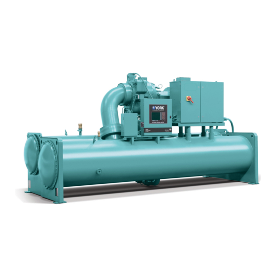
Figure 1: Model YK chiller Shipment The chiller may be ordered and shipped in any of the following forms: • Form 1 • Form 2 • Form 3 • Form 7 • Form 9 • Form 10 Form 1 Factory assembled unit, complete with motor, refrigerant, and oil charges. •... - Page 10 Johnson Controls representative. Refer to Installation - Unit (Form 160.76-N3). When more than one chiller is involved, the major parts of each unit are marked to prevent mixing of assemblies. Piping and Wiring Drawings are furnished by Johnson Controls. Form 9 Unit separate from variable speed drive.
-
Page 11: Inspection - Damage - Shortage
Report any damage or signs of possible damage to the transportation company immediately for their inspection. Johnson Controls is not be responsible for any damage in shipment, at job site, or loss of parts. Refer to Shipping Damage Claims, Form 50.15-NM. -
Page 12: Chiller Data Plate
Chiller data plate A unit data plate is mounted on the control center assembly of each unit, giving the following information: • Unit model number • Design working pressure • Water passes • Refrigerant charge • Serial numbers • Motor power characteristics and connection diagrams Additional information may be found on the motor data plate. - Page 13 Figure 3: Long term storage - tube side Item Description Tag warning Dennison 8E Gauge press 2 dia. 0-30 Tag GlvSt wire speed Bush pipe 3/4 - 14 NPTE X Valve, transducer 1/4 NPTE X Flange cover Gasket Victaulic coupling Sealing cap Model YK (Style H) Centrifugal Liquid Chillers...
- Page 14 Shipment Form 2/3/7/9 All openings on the compressor, shells including evaporator and condenser, and oil reservoir are closed and charged with nitrogen (2 psig to 3 psig). To remove the closures, sealing caps, or sealing plug under pressure is extremely dangerous, and may cause severe injury or death to the operator or people on-site.
-
Page 15: Rigging
Rigging Figure 4: Rigging warning DANGER Rigging and lifting should only be done by a professional rigger in accordance with a written rigging and lifting plan. The most appropriate rigging and lifting method depends on job specific factors, such as the rigging equipment available and site needs. Therefore, a professional rigger must determine the rigging and lifting method to be used, and it is beyond the scope of this manual to specify rigging and lifting details. -
Page 16: Location
Location YORK chillers are furnished with vibration isolator mounts for basement or ground level ® installations. Units may be located on upper floor levels providing the floor is capable of supporting the total unit operating weight and optional spring isolators are used. CAUTION Sufficient clearance to facilitate normal service and maintenance work must be provided all around and above the unit and particularly space provided at either end to permit cleaning or replacement of... -
Page 17: Foundation
Foundation A level floor, mounting pad or foundation must be provided by others, capable of supporting the operating weight of the unit. Clearance Clearances must be adhered to as follows: • Rear and above unit: 2 ft (61 cm) • Front of unit: 3 ft (91 cm) •... - Page 18 Figure 6: Neoprene isolators Unit weight 16,366 - 28,835 lb (7,424 - 13,080 kg) Unit weight up to 16,365 lb (7,423 kg) Unit weight 28,836 - 53,530 lb (13,081 - 24,281 kg) Unit weight 53,531 - 100,464 lb (24,283 - 45,559 kg) Unit weight 100,465 - 130,000 lb (45,570 - 58,967 kg) Unit weight up to 200,928 lb (up to 91,332 kg) Note: All dimensions are in inches (mm)
- Page 19 Figure 7: Neoprene isolator supports without/with skids, shipment forms 1, 2, 3, 7, 9, 10 Model YK (Style H) Centrifugal Liquid Chillers...
- Page 20 Figure 8: Spring isolators Unit weight 10,000 lb to 19,563 lb (4,536 kg to 8,873 kg) Unit weight 19,564 lb up to 35,009 lb (8,874 kg up to 15,880 kg) Unit weight 58,350 lb up to 89,340 lb (26,468 kg up to 40,525 kg) Unit weight 35,010 lb up to 58,349 lb (15,881 kg up to 26,467 kg) Unit weight 115,000 lb up to 190,000 lb (52,163 kg up to 86,183 kg) Unit weight 89,341 lb up to 115,000 lb (40,526 kg up to 52,163 kg)
-
Page 21: Installation
Note: At this point units shipped dismantled should be assembled under the supervision of a Johnson Controls representative. If the evaporator is to be field insulated, apply the insulation to the evaporator before the unit is placed in position while the unit is in the lift position. -
Page 22: Piping Connections
DWP. Inlet and outlet connections are identified by labels placed adjacent to each nozzle. The coolant temperature inside any liquid-cooled motor starter supplied by Johnson Controls must be maintained above the dewpoint temperature in the equipment room to prevent condensing water vapor inside the starter cabinet. - Page 23 Figure 9: Schematic of a typical piping arrangement Chilled water Foreign objects which could lodge in, or block flow through, the evaporator and condenser tubes must be kept out of the water circuit. All water piping must be cleaned or flushed before being connected to the chiller pumps, or other equipment.
-
Page 24: Unit Piping
On units shipped dismantled, the following piping should be completed under the supervision of the Johnson Controls representative: the lubricant piping to oil sump and oil cooler and system oil return connections using material furnished. Refer to Installation - Unit (Form 160.76- N3). - Page 25 Figure 10: Typical refrigerant vent piping Note: When installing relief piping, there must NOT be any piping strain. Relief piping must be properly aligned and supported to eliminate any possible strain. When installing relief piping, an ANSI flange or a piping union must be used to make a serviceable piping connection.
-
Page 26: Control Panel Positioning
Wiring Diagram – Unit (Style H) Field Control Modifications (Form 160.76-PW4). Note: No deviations in unit wiring from that shown on drawings furnished shall be made without prior approval of the Johnson Controls representative. Power wiring Chiller with electromechanical starter A 115 volt – single phase – 60 or 50 Hertz power supply of 20 amperes must be furnished to the... -
Page 27: Oil Pump - 3-Phase Starter
Insulation CAUTION DO NOT field insulate until the unit has been leak tested under the supervision of the Johnson Controls representative. Model YK (Style H) Centrifugal Liquid Chillers... -
Page 28: Installation Check - Request For Start-Up Service
After the unit is installed, piped, and wired as described in this Instruction, but before any attempt is made to start the unit, the Johnson Controls District Office should be advised so that the start-up service, included in the contract price, can be scheduled. Use the Installation Checklist and Request for startup, (Form 160.76-CL1). - Page 29 Table 1: Available compressor/evaporator/condenser/motor combinations Motor codes Compressor Evaporator shell codes Condenser shell codes 60 Hz 50 Hz 2C, 2D, 2E 2P, 2Q, 2R, 2S, 22, 23 4C, 4D, 4E, 4F, 4G, 4H, 4I 4P, 4Q, 4R, 4S, 42, 43, 44, 45 AC, AD, AE, AF AC, AD, AE, AF, AG, A1, A3, A8, A9 BC, BD, BE, BF...
- Page 30 Table 1: Available compressor/evaporator/condenser/motor combinations Motor codes Compressor Evaporator shell codes Condenser shell codes 60 Hz 50 Hz KC, KE, KG, KK, KL, KC, KE, KG, KK, KL, K1, K3, K5, K7, K9 K0, K1, K2, K3, K5, K7, K9 LC, LE, LG, LK, LL, LC, LE, LG, LK, LL, L1, L3, L5, L7, L9...
- Page 31 Table 1: Available compressor/evaporator/condenser/motor combinations Motor codes Compressor Evaporator shell codes Condenser shell codes 60 Hz 50 Hz SC, SE, SG, SH, SK, SC, SE, SG, SK, S1, S2, S3, S4, S5, S7, S9 S1, S2, S3, S4, S5, S7, S9 TC, TE, TG, TH, TK, TC, TE, TG, TK, T1, T2, T3, T4, T5, T7, T9...
- Page 32 Table 2: YK Mod H heat recovery combinations Motor codes Compressor Evaporator shell codes Condenser shell codes 60 Hz 50 Hz EC, ED, EE, EH, EI, EJ, EK, EM, EP, ER, CH-CT 5CE-5CO 2V, 2W, 2X E1, E3, E5, E9 EH-ET 5EE-5EO KC, KE, KG, KK, KL,...
-
Page 33: Compressor Units
Compressor units Figure 13: Dimensions – compressor units Table 3: Additional operating height clearance to floor Type of chiller mounting M dimension, in. (mm) Neoprene pad isolators 1 3/4 (45) Spring isolators 1 in. deflection 1 (25) Direct mount 3/4 in. 3/4 (19) Note: All dimensions are ft-inches (mm). - Page 34 Table 5: Dimensions of Q4 compressor units, ft-in. (mm) Q4 compressor Evaporator-condenser shell codes Series 2*-2* 4*-4* A*-A* B*-B* C*-C* D*-D* 5'-2" 5'-0" 5'-0" 5-2" 5-2" (1524) (1575) (1524) (1524) (1574) (1574) 8'-1 1/2" 8'-4 3/4" 7'-9 7/8" 7'-9 7/8" 8'-1 1/4"...
- Page 35 Table 8: Dimensions of Q7/Q8 compressor units, ft-in. (mm) Q7/Q8 Evaporator-condenser shell codes comp. Series 4*-4* 6*-4* 6*-6* C*-C* D*-D* E*-C* E*-E* F*-D* F*-F* J*-J* G*-E* E*-2* 5'-2" 5'-6" 5'-10" 5-2" 5-2" 5'-6" 6'-0" 5'-6" 6'-0" 6'-4 3/8" 6'-4 3/8" 6'-9 1/2"...
- Page 36 Table 11: Dimensions of H9 compressor units, ft-in. (mm) Evaporator-condenser shell codes compressor Series H*-F* K*-K* L*-L* O*-O* P*-P* K*-4* L*-5* 6'-4 3/8" 7'-4" 7'-4" 8'-2 7/8" 8'-2 7/8" 8'-6 3/4" 8'-6 3/4" (1940) (2236) (2236) (2510) (2510) (2610) (2610) 10'-7 7/8"...
- Page 37 Table 14: Dimensions of K3 compressor units, ft-in. (mm) K3 compressor Evaporator-condenser shell codes Series R*-R* S*-S* T*-T* U*-U* V*-V* 8'-10 7/8" 9'-4 1/2" 9'-4 1/2" 10'-2 7/8" 10'-2 7/8" (2739) (2858) (2858) (3121) (3121) 11’-6 5/16" 12’-0 13/16" 12’-0 13/16" 12’-0 5/16"...
-
Page 38: Evaporator Compact Waterboxes
Evaporator compact waterboxes Figure 14: Dimensions (end) of evaporator compact waterboxes, A through L, ft-in. (mm) Note: Nozzle orientation shown with respect to OptiView panel on evaporator. Model YK (Style H) Centrifugal Liquid Chillers... - Page 39 Figure 15: Dimensions (end) of evaporator compact waterboxes, M through Z, ft-in. (mm) Model YK (Style H) Centrifugal Liquid Chillers...
- Page 40 Table 17: Dimensions (end) of evaporator compact waterboxes, ft-in. (mm) Compact waterboxes - 150 psi round Nozzle pipe size (in.) 1-pass 2-pass 3-pass Evaporator Number of passes shell code 8" 6" 1'-3" 1'-8" 1'-1 1/2" 2'-2 1/2" — — (200) (150) (381) (508)
- Page 41 Figure 16: Dimensions (side) of evaporator compact waterboxes, ft-in. (mm) Table 18: Dimensions (side) of evaporator compact waterboxes, ft-in. (mm) One-pass evaporator shell codes Dim. G/H/J 1'-3 1'-4 1'-5 1'-7 1'-8 1'-8 1'-9 1'-11 2'-5 2'-5 2'-6 2'-8 2'-9 2'-0" 2'-0" 3/4"...
-
Page 42: Condenser Compact Waterboxes
Condenser compact waterboxes Figure 17: Dimensions (end) of condenser compact waterboxes - standard, ft-in. (mm) Note: Front side of the unit is the OptiView Control Center mounted on the evaporator. Model YK (Style H) Centrifugal Liquid Chillers... - Page 43 Table 19: Dimensions (end) of condenser compact waterboxes - standard, ft-in. (mm) Compact waterboxes - 150 psi round Nozzle pipe size (in.) 1-pass 2-pass 3-pass Condenser Number of passes shell code 10" 6" 6" 1'-3" 2'-4" 1'-9 1/2" 2'-10 1/2" 1'-9 1/2"...
- Page 44 Figure 18: Dimensions (side) of condenser compact waterboxes - standard, ft-in. (mm) Table 20: Dimensions (side) of condenser compact waterboxes - standard, ft-in. (mm) One-pass condenser shell codes Dim. E/F/J 1'-1 1'-1 1'-6 1'-7 1'-8 1'-9 1'-10 1'-11 1'-11 2'-4 2'-5 2'-6 1'-3"...
-
Page 45: Condenser Heat Recovery Compact Waterboxes
Condenser heat recovery compact waterboxes Figure 19: Dimensions of condenser heat recovery compact waterboxes - standard, ft-in. (mm) Table 21: Dimensions of condenser heat recovery compact waterboxes - standard, ft-in. (mm) Compact water boxes-150 psi (rectangular) Nozzle pipe size (in.) Main bundle Heat recovery bundle 1,2, or 3 pass 2 pass... -
Page 46: Evaporator Marine Waterboxes
Evaporator marine waterboxes Figure 20: Dimensions (end) of evaporator marine waterboxes, ft-in. (mm) Table 22: Dimensions (end) of evaporator marine waterboxes, ft-in. (mm) Evaporator 1-pass Evaporator 2-pass Evaporator 3-pass Note: Nozzle orientation shown with respect to OptiView panel on evaporator. Model YK (Style H) Centrifugal Liquid Chillers... - Page 47 Table 23: Dimensions (end) of evaporator marine waterboxes, ft-in. (mm) Marine waterboxes - 150 psi round Nominal nozzle pipe size (in.) 1-pass 2-pass 3-pass Evaporator shell code Number of passes 8" 6" 1'-3" 3'-7" 3'-7" 1'-0" 1'-4 1/2" — — —...
- Page 48 Figure 21: Dimensions (side) of evaporator marine waterboxes, ft-in. (mm) Table 24: Dimensions (side) of evaporator marine waterboxes, ft-in. (mm) 1-pass 2-pass 3-pass Evaporator shell code 1'-6 7/8" 0'-8 13/16" 1'-4 5/8" 0'-7 5/8" 0'-5 11/16" — — (479) (224) (419) (194) (144) 1'-8 5/8"...
-
Page 49: Condenser Marine Waterboxes
Condenser marine waterboxes Figure 22: Dimensions (end) of condenser marine waterboxes, ft-in. (mm) Table 25: Condenser 1-pass Condenser 1-pass Condenser 2-pass Condenser 3-pass Note: Nozzle orientation shown with respect to OptiView panel on evaporator. Model YK (Style H) Centrifugal Liquid Chillers... - Page 50 Table 26: Dimensions (end) of condenser marine waterboxes, ft-in. (mm) Condenser waterboxes - 150 psi round Nominal nozzle Cond. pipe size (in.) 1-pass 2-pass 3-pass shell Number of passes code 10" 6" 6" 1'-3" 4'-5" 4'-5" 1'-8" 1'-4 1/2" 4'-5" 1'-8"...
- Page 51 Figure 23: Dimensions (side) of condenser marine waterboxes, ft-in. (mm) Table 27: Dimensions (side) of condenser marine waterboxes, ft-in. (mm) 1-pass 2-pass 3-pass Condenser shell code 1'-9" 0'-9 7/8" 1'-4 3/4" 0'-7 3/4" 0'-5 7/8" 1'-4 3/4" 0'-7 3/4" (533) (251) (425) (197) (150)
-
Page 52: Weights
Weights Note: The weights provided in the following table are intended to be a general reference only. The weights are based on the heaviest anticipated unit combinations as of December 2020. There are numerous factors that can impact these values based on the chiller options selected at the time of the final unit rating. - Page 53 The values in the following table for evaporator marine waterbox weights are to be added to standard unit weights shown on Table 28. Table 29: Approximate evaporator marine waterbox weights, lb (kg) Shipping weight increase, lb (kg) Operating weight increase, lb (kg) Unit Compressor 1-pass...
- Page 54 The values in the following table for condenser marine waterbox weights are to be added to standard unit weights shown in Table 28. Table 30: Approximate condenser marine waterbox weights, lb (kg) Shipping weight increase, lb (kg) Operating weight increase, lb (kg) Unit Compressor 1-pass...
-
Page 55: Unit Conversion
Unit conversion The following factors can be used to convert from English to the most common SI metric values. Table 31: SI metric conversion Measurement Multiply English unit By factor To obtain metric unit Capacity Tons refrigerant effect (ton) 3.516 Kilowatts (kW) Power Horsepower... - Page 56 © 2021 Johnson Controls. 5000 Renaissance Drive, New Freedom, York, PA 17349, USA. Subject to change without notice. All rights reserved.
Need help?
Do you have a question about the YORK YK Series and is the answer not in the manual?
Questions and answers