
Related Manuals for Johnson Controls York YKEP Series


Summary of Contents for Johnson Controls York YKEP Series
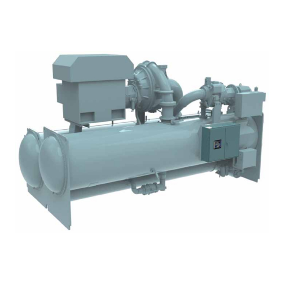
- Page 1 CENTRIFUGAL LIQUID CHILLER WITH ECONOMIZER COMPRESSOR CONTROL CENTER OPERATION Form 160.77-02 (611) Form 160.77-02 (1111) MODEL YKEP 2700 - 3200 TON LD15301a R-134a Issue Date: November 15, 2011...
- Page 2 All wiring must be in accordance with Johnson Controls’ published specifications and must be performed only by a qualified electrician. Johnson Controls will NOT be responsible for damage/problems resulting from improper connections to the controls or application of improper control signals.
- Page 3 FORM 160.77-O2 ISSUE DATE: 11/15/2011 CHANGEABILITY OF THIS DOCUMENT In complying with Johnson Controls’ policy for con- Operating/service personnel maintain responsibility for tinuous product improvement, the information con- the applicability of these documents to the equipment. tained in this document is subject to change without If there is any question regarding the applicability of notice.
- Page 4 FORM 160.77-O2 ISSUE DATE: 11/15/2011 THIS PAGE INTENTIONALLY LEFT BLANK JOHNSON CONTROLS...
-
Page 5: Table Of Contents
TABLE 3 - Modbus RTU Slot List ..........................93 TABLE 4 - Status Line Messages and Colors .......................109 TABLE 5 - LCSSS High Supply Line Voltage Thresholds ..................118 TABLE 6 - LCSSS Low Supply Line Voltage Thresholds ..................118 TABLE 7 - Over-Current Trip ..........................123 JOHNSON CONTROLS... - Page 6 FIGURE 45 - Comms Screen ..........................86 FIGURE 46 - Alarm History Screen .........................88 FIGURE 47 - Active Alarms Screen .........................89 FIGURE 48 - Trip Status Screen ..........................90 FIGURE 49 - Trending Screen ..........................91 FIGURE 50 - System Status / System Details.......................109 JOHNSON CONTROLS...
-
Page 7: Section 1 - Ykep Chiller Overview
• The Leaving Chilled Liquid Temperature is not be- low Setpoint 2. When the calculated gas flow through the primary compressor reaches a prescribed threshold as fol- • The Economizer Saturation Temperature is not below the Target Temperature JOHNSON CONTROLS... -
Page 8: Figure 2 - Ykep Chiller System Diagram
PRIMARY COMPRESSOR ECONOMIZER COMPRESSOR (OPTIONAL) HOT GAS BYPASS VALVE CHECK VALVE CONDENSER EVAPORATOR COOLING CHILLED LIQUID SUBCOOLER LIQUID LEVEL ECONOMIZER ECONOMIZER LEVEL SUBCOOLER LEVEL VALVE ECONOMIZER LEVEL VALVE LD16021 FIGURE 2 - YKEP CHILLER SYSTEM DIAGRAM JOHNSON CONTROLS... -
Page 9: Figure 3 - Ykep Chiller Operation Sequence Timing Diagram
(0.17) (0.22) (0.75) (0.83) (1.83) CLOSED RESTART AFTER ANTI-RECYCLE START STOP (FOR EM STARTERS, 30 MIN) (FOR VSD STARTERS, 5 STARTS THEN 10 MIN) TIME IN SECONDS (MINUTES) LD16023 FIGURE 3 - YKEP CHILLER OPERATION SEQUENCE TIMING DIAGRAM JOHNSON CONTROLS... - Page 10 At no time will the valve that opens for compressor run. control allow the oil heaters to continue to operate with oil temperature above 160°F. JOHNSON CONTROLS...
-
Page 11: Figure 4 - Ykep Chiller Oil Management System
FORM 160.77-O2 SECTION 1 - YKEP CHILLER OVERVIEW ISSUE DATE: 11/15/2011 LD16022 FIGURE 4 - YKEP CHILLER OIL MANAGEMENT SYSTEM JOHNSON CONTROLS... - Page 12 In the event of high motor power, the capacity In cases of light load and low head, the economizer control signal is over-ridden and the compressor compressor is dropped offline and the unit will be run PRV's are closed to keep the motor power down. JOHNSON CONTROLS...
-
Page 13: Figure 5 - Capacity Control Model
The hot gas bypass valve is used primarily at low needed. loads to maintain a minimum suction gas flow re- quired by the compressor for stability. When the • On a water chilling application, this valve compressor has reduced capacity to its minimum goes open on shutdown. JOHNSON CONTROLS... - Page 14 JOHNSON CONTROLS...
-
Page 15: Figure 6 - System Anti-Surge Map
MVP1 % VANES line right several percent, to increase refrigerant LD15231 flow, by supplementing hot gas. FIGURE 6 - SYSTEM ANTI-SURGE MAP • Repeat the procedure for low head operation. • At the lowest condensing temperature, start reduc- JOHNSON CONTROLS... - Page 16 • Repeat the process as needed for head and mini- speed anti-surge tuning should be performed before mum speed points SPD2, SPD3, SPD4 and MSP2, adjusting the PRV anti-surge line. MSP3, MSP4 between the endpoints to further define the surge line. JOHNSON CONTROLS...
-
Page 17: Section 2 - Ykep Control Center Introduction
12, gasketed enclosure. sures in PSIG) and Metric (temperatures in °C and • The panel displays real-time chiller sensor data pressures in BAR) mode. The advantages are most via the PAC and allows for manual adjustments to operational parameters. JOHNSON CONTROLS... -
Page 18: Table 1 - Ykep Control System Sensors
PWM1 Primary Compressor Oil Pump Speed PE-111 Evaporator Refrigerant Pressure PWM2 Economizer Compressor Oil Pump Speed PE-113 Condneser Refrigerant Pressure RST-100 Leaving Chilled Liquid Remote Setpoint PE-116 Economizer Refrigerant Pressure RST-160 Remote Demand Limit PE-140 Oil Sump Pressure JOHNSON CONTROLS... -
Page 19: Figure 9 - Ykep Control System Sensors
ZE-100B ZS-142B TE-113 LE-116 VSDA PCV-112A VSDB ZE-149A PWM1 ZE-100A PWM2 FSLL-103 PE-113 PE-149B TCV-100A ZS-100A PE-116 PE-140 TE-114 LCV-114 TE-140 TE-111 LCV-116 TE-103 PE-111 TE-102 LE-114 FSLL-100 TE-100 TE-101 LD15304 FIGURE 9 - YKEP CONTROL SYSTEM SENSORS JOHNSON CONTROLS... - Page 20 FORM 160.77-O2 ISSUE DATE: 11/15/2011 THIS PAGE INTENTIONALLY LEFT BLANK JOHNSON CONTROLS...
-
Page 21: Section 3 - Ykep Control Panel Operation
Each screen description in this document will begin with a section entitled “Overview” which will describe the graphical elements on the screen and give a short JOHNSON CONTROLS... -
Page 22: Figure 11 - Security Manager
Access Level without returning to the Home screen. this point, the user will be prompted to Log-On to the Security System (see Figure 11 on Page 22), enter a After login, the user may then modify setpoints on that Username, and the corresponding password. screen. JOHNSON CONTROLS... -
Page 23: Figure 14 - Setpoint Program Dialog Box
Figure 16 on Page 24 shows the layout of all the screens and where each are located Manual Controls in relation to each other. Some keys are used to perform manual control func- tions. These may involve manual control of items such JOHNSON CONTROLS... -
Page 24: Figure 16 - Navigation
ECONOMIZER CAPACITY ALARM HISTORY OIL SUMP CAPACITY CONTROLS CAPACITY TUNING ANTI-SURGE CAPACITY LIMITS ECONOMIZER CAPACITY SETPOINTS LOG VIEWER SALES ORDER COMMUNICATIONS ALARM HISTORY ACTIVE ALARMS TRIP STATUS TRIP 1 - TRIP 5 ALARM HISTORY TRENDING FIGURE 16 - NAVIGATION JOHNSON CONTROLS... -
Page 25: Home Screen
Displays the current length of time the Primary Motor ning. has been running. Economizer Motor Run (LED) Economizer Runtime LED is illuminated when the Economizer Motor is run- Displays the current length of time the Economizer ning. Motor has been running. JOHNSON CONTROLS... - Page 26 Advances to a detailed view of all evaporator param- minate lighter green, when the system start is enabled, eters, including the programmable local leaving chilled waiting for either a pre-lube or a cycling shutdown to liquid setpoint. reset. JOHNSON CONTROLS...
- Page 27 Local or Remote control, and Program- mable chilled liquid temperature settings. Alarm History This screen provides a historical log of events with a timestamped record of when the events have occured. JOHNSON CONTROLS...
-
Page 28: System Screen
(provided by feedback po- Oil Sump Pressure tentiometer ZE-149A). Displays the pressure in the oil sump (provided by pressure transducer PE-140). Pri Motor Load Displays the percentage of full load amps (FLA) uti- lized by the primary motor. JOHNSON CONTROLS... - Page 29 Displays the temperature of the refrigerant at the subcooler (provided by RTD TE-114). Target Displays the target economizer saturation temperature Subcooler Valve when the economizer compressor is running. Displays the open percentage of the subcooler level con- trol valve (provided by actuator feedback LCV-114). JOHNSON CONTROLS...
- Page 30 Displays the present refrigerant pressure in the evapo- “M” shows next to a parameter presently under Man- rator (provided by transducer PE-111), above the pres- ual Control. ent refrigerant temperature in the evaporator (provided by RTD TE-111). JOHNSON CONTROLS...
- Page 31 FORM 160.77-O2 SECTION 3 - YKEP CONTROL PANEL OPERATION ISSUE DATE: 11/15/2011 THIS PAGE INTENTIONALLY LEFT BLANK JOHNSON CONTROLS...
-
Page 32: Manual / Auto Stations Screen
100B). liquid exits the evaporator (provided by RTD TE-101). Condenser Pressure Displays the refrigerant pressure in the condenser (pro- vided by transducer PE-113). Evaporator Pressure Displays the present refrigerant pressure in the evapo- rator (provided by trasducer PE-111). JOHNSON CONTROLS... - Page 33 Auto, and if they Auto/Manual key is red the control is set to manual. Open This key sends an open command to the primary com- pressor PRV. The primary compressor PRV will open 1% for each depress, hold for repeat. JOHNSON CONTROLS...
-
Page 34: Subcooler Screen
Valve. When the Auto/Manual key is grey the control is tuator LCV-114. set to Auto, and if they key is red the control is manual. Evaporator Pressure Displays the present refrigerant pressure in the evapo- rator (provided by transducer PE-111). JOHNSON CONTROLS... - Page 35 Zone 1 is the steady state control loop gains, when the process variable is near setpoint. Zone 2 is the transient and more aggressive control loop gains when the process variable is far away from setpoint, and needs to be returned to setpoint more quickly. JOHNSON CONTROLS...
-
Page 36: Economizer Screen
This key sends an open command to the Economizer rator (provided by transducer PE-111). Valve. The Economizer Valve will increase 1% for each depress, hold for repeat. Economizer Pressure Displays the present refrigerant pressure in the econo- mizer (provided by transducer PE-116). JOHNSON CONTROLS... - Page 37 Zone 1 is the steady state control loop gains, when the process variable is near setpoint. Zone 2 is the transient and more aggressive control loop gains when the process variable is far away from setpoint, and needs to be returned to setpoint more quickly. JOHNSON CONTROLS...
-
Page 38: Evaporator Screen
Actual Chilled Liquid Setpoint Small Temperature Difference Displays the present setpoint to which the chiller is op- Displays the difference between the leaving chilled liq- erating, whether controlled locally or remotely. uid temperature (TE-100) and the evaporator refriger- ant temperature (TE-111). JOHNSON CONTROLS... - Page 39 This value allows the user to define the leaving chilled liquid temperature that is to be maintained by the chill- er. The temperature is programmable over the range of 38.0°F to 70.0°F (water) or variable range (brine), de- pending on the brine concentration, freezing point, etc. JOHNSON CONTROLS...
-
Page 40: Hot Gas Screen
PE-113). mary High Pressure Switch contacts are open, indicat- ing a fault condition (provided by Primary Compressor Evaporator Pressure High Discharge Pressure Cutout PSHH-113A). Displays the present refrigerant pressure in the evapo- rator (provided by pressure transducer PE-111). JOHNSON CONTROLS... - Page 41 The Hot Gas Valve will increase 1% for each depress, hold for repeat. Close Access Level Required: OPERATOR This key sends a close command to the Hot Gas Valve. The Hot Gas Valve will decrease 1% for each depress, hold for repeat. JOHNSON CONTROLS...
-
Page 42: Condenser Screen
Primary Displays the refrigerant pressure in the condenser (pro- High Pressure Switch contacts are open, indicating a vided by transducer PE-113). fault condition (Primary Compressor High Discharge Pressure Cutout PSHH-113A). JOHNSON CONTROLS... - Page 43 Causes an instant navigation to the Subcooler Screen. Economizer Vessel PROGRAMMABLE Causes an instant navigation to the Economizer Vessel None Screen. Hot Gas Causes an instant navigation to the Hot Gas Screen. Alarm History Causes an instant navigation to view the Alarm History Screen. JOHNSON CONTROLS...
-
Page 44: Primary Compressor Screen
_ _._ when either of the transducers used to calculate discharge of the compressor before the refrigerant en- oil pressure are out of range. The zero function occurs when the RESET button is pressed, the oil pumps are JOHNSON CONTROLS... - Page 45 Displays the motor current as a percentage of the Full Load Amps (FLA) value. sub-screen allowing calibration of the High Speed Thrust Bearing Proximity Probe Sensor. System Head PRV Calibrate Displays the chiller head pressure calculated as (con- Access Level Required: OPERATOR JOHNSON CONTROLS...
- Page 46 Primary Motor Causes an instant navigation to view the Primary Mo- tor Screen. Capacity Controls Causes an instant navigation to view the Capacity Con- trols Screen. Alarm History Causes an instant navigation to view the Alarm History Screen. JOHNSON CONTROLS...
- Page 47 FORM 160.77-O2 SECTION 3 - YKEP CONTROL PANEL OPERATION ISSUE DATE: 11/15/2011 THIS PAGE INTENTIONALLY LEFT BLANK JOHNSON CONTROLS...
-
Page 48: Primary Proximitor Calibration Screen
This button cancels the request for a primary compres- Compressor Oil Pressure sor proximitor calibration procedure. Displays the primary compressor oil pressure. Calibration Active (LED) Illuminates when the primary compressor is currently performing a proximitor calibration. JOHNSON CONTROLS... - Page 49 Factory Technical Support Team. NAVIGATION Previous Returns the display to the previous screen. Oil Sump Causes an instant navigation to the Oil Sump Screen. Alarm History Causes an instant navigation to the Alarm History Screen. JOHNSON CONTROLS...
-
Page 50: Prv Calibration Screen
Illuminates when the Pre-rotational Vanes are in the Active (LED) process of opening (provided by TCV-100A). Illuminates when the Primary Compressor is perform- PRV Motor Closing (LED) ing a calibration procedure. Illuminates when the Pre-rotational Vanes are in the process of closing (provided by TCV-100A). JOHNSON CONTROLS... - Page 51 This button cancels the request for a proximitor cali- bration procedure. Secondary Calibration Access Level Required: OPERATOR Start This button activates a proximitor probe calibration procedure to begin. Cancel This button cancels the request for a proximitor cali- bration procedure. JOHNSON CONTROLS...
-
Page 52: Oil Sump Screen
(provided by prelube. If either of the transducers used to calculate transducer PE-141A). this differential are out of range, the display field will show “XX.X” (provided by transducer PE-140). JOHNSON CONTROLS... - Page 53 The Manual Pump key is not displayed during system prelube, system run and system coastdown. Run Pump Auto Access Level Required: OPERATOR This key allows the oil pump to operate under auto control. JOHNSON CONTROLS...
-
Page 54: Primary Variable Geometry Diffuser Screen
(extending) (provided by PCV- 112A). Access Level Required: OPERATOR This key allows the user to program the maximum Stall Pri VGD Position Noise setpoint. Displays the Primary Compressor VGD position (pro- vided by VGD Position Potentiometer ZE-149A). JOHNSON CONTROLS... - Page 55 Cal Max Access Level Required: SERVICE This key allows the technician to define the minimum potentiometer reading when the VGD is fully closed (extended). This value is set automatically, after a cali- bration cycle is performed. JOHNSON CONTROLS...
-
Page 56: Primary Motor Screen (Em Starter)
Motor Current Limit value dur- ing this time period. This function is used to provide energy savings following a chiller start-up. Displays the control value for the primary motor, de- mand limiter function. JOHNSON CONTROLS... - Page 57 (minutes per repeat) for the demand limit. This key allows the technician to set the derivative gain for the demand limit. Motor Lube Ack. Access Level Required: SERVICE This key allows the user to reset the runtime until next motor lube. JOHNSON CONTROLS...
-
Page 58: Primary Motor Screen (Mv Sss)
Displays the time remaining in the programmed pulldown period when the value is non-zero. Displays the number of cross checking errors from the SSS communications link, for troubleshooting purposes. Input Power Displays the input power for the primary motor. JOHNSON CONTROLS... - Page 59 This key allows the technician to specify the maximum amperage that the motor will draw when the motor is performing a start-up. Starter Rated FLA Access Level Required: SERVICE This key allows the technician to program the Starter Rated Full Load Amps (FLA). JOHNSON CONTROLS...
-
Page 60: Primary Motor Screen (Mv Vsd)
Load Amps setpoint. Displays the average of the 3-phase input voltage to the MV VSD (provided by the MV VSD). Current Limit Setpoint Displays the current limit in use, this value can be a locally or remote programmed value. JOHNSON CONTROLS... - Page 61 (as a percentage of FLA) to which the chiller will be limited during the specified pulldown limit time. This value will overrride the Motor Current Limit value dur- ing this time period. This function is used to provide energy savings following a chiller start-up. JOHNSON CONTROLS...
-
Page 62: Capacity Controls Screen With Hot Gas (Fixed Speed)
PRV Ramp Rate PC-111 Low Press Override Displays the opening rate at which the Pre-rotational Evap Pressure Vanes are commanded to open, during startup. Displays the current Evaporator Pressure (provided by transducer PE-111). JOHNSON CONTROLS... - Page 63 Screen. HGV Control Displays the open percentage of the Hot Gas Bypass Valve (provided by Hot Gas Valve Actuator TCV- 100C). Hot Gas Ramp Displays the percentage that the Hot Gas Valve is lim- ited to during startup. JOHNSON CONTROLS...
-
Page 64: Capacity Controls Screen Without Hot Gas (Fixed Speed)
PRV Ramp Rate PC-111 Low Press Override Displays the opening rate at which the Pre-rotational Evap Pressure Vanes are commanded to open. Displays the current Evaporator Pressure (provided by transducer PE-111). JOHNSON CONTROLS... - Page 65 Close (LED) Economizer Capacity Illumintated when the primary compressor PRV is Access Level Required: OPERATOR closing. Causes an instant navigation to the Economizer Capac- ity Screen. Alarm History Causes an instant navigation to view the Alarm History Screen. JOHNSON CONTROLS...
-
Page 66: Capacity Controls Screen (Speed Option)
PRV Ramp Rate C-111 Low Press Override Displays the opening rate at which the Pre-rotational Evap Pressure Vanes are commanded to open, during startup. Displays the current Evaporator Pressure (provided by transducer PE-111). JOHNSON CONTROLS... - Page 67 Displays the control percentage of the Hot Gas Bypass Valve. HGV Control Displays the open percentage of the Hot Gas Bypass Valve (provided by TCV-100C). Hot Gas Ramp Displays the percentage that the Hot Gas Valve is lim- ited to during startup. JOHNSON CONTROLS...
-
Page 68: Capacity Controls Screen (Vane Anti-Surge)
PRV Ramp Rate PC-111 Low Press Override Displays the opening rate at which the Pre-rotational Evap Pressure Vanes are commanded to open, during startup. Displays the current Evaporator Pressure (provided by transducer PE-111). JOHNSON CONTROLS... - Page 69 TV-100A PRV Manual Auto Displays the open percentage of the Pre-rotational Causes an instant navigation to the Manual Auto Vanes (provided by Primary Compressor PRV Pot ZE- Screen. 100A). Open (LED) Illuminated when the primary compressor PRV is opening. JOHNSON CONTROLS...
-
Page 70: Primary Capacity Tuning Screen
Allows the technician to program the integral gain IC-160A Primary Demand Limit (minutes per repeat) for the speed. Displays the Primary Demand Limit Process Variable Allows the technician to program the derivative gain (PV) percentage. for the speed. JOHNSON CONTROLS... - Page 71 Screen. Alarm History Access Level Required: OPERATOR Causes an instant navigation to view the Alarm History Allows the user to specify the current limit value (as a Screen. percentage of FLA) to which the chiller will be limited JOHNSON CONTROLS...
-
Page 72: Primary Anti-Surge Screen
The line is are plotted on the map to adjust the line. defined by the following points: JOHNSON CONTROLS... - Page 73 Minimum speed to avoid surge at the pressure differen- tial defined by SPD2. MSP3 Minimum speed to avoid surge at the pressure differen- tial defined by SPD3. MSP4 Minimum speed to avoid surge at the pressure differen- tial defined by SPD4. JOHNSON CONTROLS...
-
Page 74: Capacity Limits Screen
Allows the user to program the derivative gain for the speed. Displays the High Discharge Override Process Vari- Hot Gas able (PV) pressure. Allows the user to program the proportional gain for Displays the High Discharge Override Control Value the Hot Gas Valve. (CV) percentage. JOHNSON CONTROLS... - Page 75 Allows the user to program the proportional gain for the High Discharge Override. Allows the user to program the integral gain (minutes per repeat) for the High Discharge Override. Allows the user to program the derivative gain for the High Discharge Override. JOHNSON CONTROLS...
-
Page 76: Economizer Compressor Screen
(provided by RTD TE-113). oil pressure are out of range. The zero function occurs when the RESET button is pressed, the oil pumps are not running, and there are no system faults or alarms. JOHNSON CONTROLS... - Page 77 – evaporator pressure/evaporator pres- sure). Causes an instant navigation to view the Economizer Capacity Controls Screen. Economizer Runtime Displays the most recent runtime for the Economizer Alarm History Compressor. Causes an instant navigation to view the Alarm History Screen. JOHNSON CONTROLS...
-
Page 78: Economizer Motor Lcsss Screen
Temperature – Phase A, B, C locally or remotely programmed value. Displays the temperatures of the starter Silicon Con- trolled Rectifier assemblies per phase. Input Power Displays the input power for the economizer compres- sor motor as reported from the starter. JOHNSON CONTROLS... - Page 79 Disable overvoltage and un- dervoltage shutdown protection. The thresholds are set based on the nominal line voltage range. Reset kWh Access Level Required: SERVICE This key allows the technician to reset the cumulative kWh. JOHNSON CONTROLS...
-
Page 80: Economizer Capacity Screen
Economizer Motor Run (LED) perature in the economizer vessel to which the control Illuminates when the digital output from the control system is controlling the economizer capacity in any center is commanding the Economizer Motor to run. operating mode. JOHNSON CONTROLS... - Page 81 Causes an instant navigation to view the Alarm History Full Load motor current. Screen. Min Start Manual Auto Displays the minimum PRV position commanded at Causes and instant navigation to the Manual / Auto the time of starting the economizer compressor. Stations Screen. JOHNSON CONTROLS...
-
Page 82: Setpoints Screen
Displays the current revision level to the ladder logic. Remote SP Displays how Remote Setpoint Communications are established, provided by control transmitter (RST-100) or over the network protocol. Leaving Chilled Liquid Temperature Displays the current actual Leaving Chilled Liquid Temperature. JOHNSON CONTROLS... - Page 83 Allows the operator to select how the Remote Start Causes an instant navigation to the Communication Command is communicated. Screen. Local Chilled Setpoint Allows the operator to program the Local Chilled Setpoint. Restart Allows the operator to program the Chilled Liquid Re- start temperature. JOHNSON CONTROLS...
-
Page 84: Factory Setup Screen
This screen is available for view of the displayed set- tings pertinent to the chiller configuration. These pa- rameters are critical to the operation of the control sys- tem and are set at the Factory level before shipment and should not be changed. JOHNSON CONTROLS... - Page 85 FORM 160.77-O2 SECTION 3 - YKEP CONTROL PANEL OPERATION ISSUE DATE: 11/15/2011 THIS PAGE INTENTIONALLY LEFT BLANK JOHNSON CONTROLS...
-
Page 86: Comms Screen
WAN Mask the Chiller LAN network port. The MAC address is Displays the subnet mask of the Chiller WAN network port. static and will not change. LAN Ethernet IP Displays the IP address of the Chiller LAN network port. JOHNSON CONTROLS... - Page 87 AVOID REBOOTING WHILE THE - Unit Wiring and Field Control Modification (Form CHILLER IS RUNNING. 160.77-PW2) for wiring details. NODE Define the node number for use with the Modbus port. BAUD Define the baud rate of communication via the Modbus port. JOHNSON CONTROLS...
-
Page 88: Alarm History Screen
Active Alarms Displays the date and time the alarm ocurred and its Causes an instant navigation to the Active Alarms current status. screen. Previous Returns the display to the previous alarm. Next Returns the display to the next alarm. JOHNSON CONTROLS... -
Page 89: Active Alarms Screen
This screen allows the user to browse through the ac- tive system alarms. NAVIGATION Previous DISPLAY ONLY Returns the display to the previous screen. Active Alarms Home Displays the date, time and active system fault. Causes an instant navigation to the Home Screen. screen. PROGRAMMABLE JOHNSON CONTROLS... -
Page 90: Trip Status Screen
Displays the actual time the trip occurred. Trip 1 - Trip 5 Each key displays the peticular historical event into the display buffer. The display buffer is only updated when a Trip 1 - Trip 5 key is pressed. JOHNSON CONTROLS... -
Page 91: Trending Screen
Trend Pen Assignments are shown in Table 2 on Page 92. > Allows the operator to advance trending view forward. NAVIGATION >> Allows the operator to instantly navigate to the end of Previous the trending. Returns the display to the previous screen. JOHNSON CONTROLS... -
Page 92: Table 2 - Trend Pen Assignments
Hot Gas Bypass Valve Subcooler Variable Orifice Valve Economizer Variable Orifice Valve Reserved PRI Comp VS Oil Pump Drive Control SEC Comp VS Oil Pump Drive Control System Head (Cond Pres - Evap Pres) Evaporator Small Diff Temp JOHNSON CONTROLS JOHNSON CONTROLS... -
Page 93: Section 4 - Modbus Rtu Slot List
N13:1/6 DO_HS_OilPumpRun 10024 N13:1/7 DO_RemoteReadyToStart 10025 N13:1/8 spare 10026 N13:1/9 spare 10027 N13:1/10 spare 10028 N13:1/11 spare 10029 N13:1/12 spare 10030 N13:1/13 spare 10031 N13:1/14 spare 10032 N13:1/15 spare 10033 N13:2/0 DO_LSPRV_Open 10034 N13:2/1 DO_LSPRV_Close 10035 N13:2/2 DO_HSPRV_Open JOHNSON CONTROLS... - Page 94 Subcooler Refrig. Liquid Level 30224 F10:12 AI_LE116.Scaled Economizer Refrig. Liquid Level 30226 F10:13 ZC_142A.ProxDifferential PRI Comp SEC Thrust Bearing Probe Gap 30228 F10:14 C_LSKW+C_HSKW System Kilowatts 30230 F10:15 C_LSPRVPosition PRIMARY PRV Position 30232 F10:16 C_HSPRVPosition SECONDARY PRV Position JOHNSON CONTROLS...
- Page 95 PRI Minimum Antisurge Frequency 30426 F11:13 C_HSComprHead SEC Compressor Head 30428 F11:14 CC_LSR1 LSR1 30430 F11:15 CC_LSR2 LSR2 30432 F11:16 CC_LSR3 LSR3 30434 F11:17 CC_LSR4 LSR4 30436 F11:18 CC_HSR1 HSR1 30438 F11:19 CC_HSR2 HSR2 30440 F11:20 CC_HSR3 HSR3 JOHNSON CONTROLS...
- Page 96 ALM_LS_UnscheduledRot WARNING: PRIMARY MOTOR CURRENT DETECTED WITHOUT RUN 10108 N12:0/8 ALM_HS_Unschedule- WARNING: ECONOMIZER MOTOR CURRENT DE- dRot TECTED WITHOUT RUN 10109 N12:0/9 ALARM SPARE W0 B9 10110 N12:0/10 ALARM SPARE W0 B10 10111 N12:0/11 ALARM SPARE W0 B11 JOHNSON CONTROLS...
- Page 97 TRIP: COMMUNICATIONS FAULT WITH SLOT 3 10151 N12:3/3 TRIP_CommFlt_Slot4 TRIP: COMMUNICATIONS FAULT WITH SLOT 4 10152 N12:3/4 TRIP_CommFlt_Slot5 TRIP: COMMUNICATIONS FAULT WITH SLOT 5 10153 N12:3/5 TRIP_CommFlt_Slot6 TRIP: COMMUNICATIONS FAULT WITH SLOT 6 10154 N12:3/6 TRIP_CommFlt_Slot7 TRIP: COMMUNICATIONS FAULT WITH SLOT 7 JOHNSON CONTROLS...
- Page 98 ALARM SPARE W5 B12 10193 N12:5/13 ALARM SPARE W5 B13 10194 N12:5/14 ALARM SPARE W5 B14 10195 N12:5/15 ALARM SPARE W5 B15 10196 N12:6/0 AI_5VOLTSUPPLY.OOR 5 VOLT SUPPLY OUT OF RANGE 10197 N12:6/1 AI_5VOLTSUPPLY.AL 5 VOLT SUPPLY LOW JOHNSON CONTROLS...
- Page 99 OIL SUMP PRESSURE VERY LOW 10239 N12:8/11 AI_PE140.AH OIL SUMP PRESSURE HIGH 10240 N12:8/12 AI_PE140.AHH OIL SUMP PRESSURE VERY HIGH 10241 N12:8/13 AI_PE141A.OOR PRIMARY OIL PUMP PRESSURE OUT OF RANGE 10242 N12:8/14 AI_PE141A.AL PRIMARY OIL PUMP PRESSURE LOW JOHNSON CONTROLS...
- Page 100 ENTERING CONDENSER LIQUID TEMP LOW 10283 N12:11/7 AI_TE102.ALL ENTERING CONDENSER LIQUID TEMP VERY LOW 10284 N12:11/8 AI_TE102.AH ENTERING CONDENSER LIQUID TEMP HIGH 10285 N12:11/9 AI_TE102.AHH ENTERING CONDENSER LIQUID TEMP VERY HIGH 10286 N12:11/10 AI_TE103.OOR LEAVING CONDENSER LIQUID TEMP OUT OF RANGE JOHNSON CONTROLS...
- Page 101 N12:14/3 AI_ZE100A.AL PRIMARY PRV POSITION LOW 10328 N12:14/4 AI_ZE100A.ALL PRIMARY PRV POSITION VERY LOW 10329 N12:14/5 AI_ZE100A.AH PRIMARY PRV POSITION HIGH 10330 N12:14/6 AI_ZE100A.AHH PRIMARY PRV POSITION VERY HIGH 10331 N12:14/7 AI_ZE100B.OOR SECONDARY PRV POSITION OUT OF RANGE JOHNSON CONTROLS...
- Page 102 10363 N12:16/7 YPWMP_LS_PRV.Cal_ LS PRV CALIBRATION COMPLETED Complete 10364 N12:16/8 YPWMP_LS_VGD.Cal_ LS VGD CALIBRATION STARTED Active 10365 N12:16/9 YPWMP_LS_VGD.Cal_ LS VGD CALIBRATION COMPLETED Complete 10366 N12:16/10 YPWMP_HS_PRV.Cal_ HS PRV CALIBRATION STARTED Active 10367 N12:16/11 ALARM SPARE W17 B11 JOHNSON CONTROLS...
- Page 103 SSS_HS.Alarms[2].4 SEC SSS: SPARE W2 B4 10409 N12:19/5 SSS_HS.Alarms[2].5 SEC SSS: SPARE W2 B5 10410 N12:19/6 SSS_HS.Alarms[2].6 SEC SSS: SPARE W2 B6 10411 N12:19/7 SSS_HS.Alarms[2].7 SEC SSS: SPARE W2 B7 10412 N12:19/8 SSS_HS.Alarms[2].8 SEC SSS: SPARE W2 B8 JOHNSON CONTROLS...
- Page 104 PRI SSS FAULT: SPARE WORD1 BIT1 10454 N12:22/2 SSS_LS.Alarms[1].2 PRI SSS FAULT: HIGH TEMPERATURE 10455 N12:22/3 SSS_LS.Alarms[1].3 PRI SSS FAULT: SPARE WORD1 BIT3 10456 N12:22/4 SSS_LS.Alarms[1].4 PRI SSS FAULT: SPARE WORD1 BIT4 10457 N12:22/5 SSS_LS.Alarms[1].5 PRI SSS FAULT: SPARE WORD1 BIT5 JOHNSON CONTROLS...
- Page 105 PRI VSD FAULT: MAIN CONTROL BOARD FAULT 10495 N12:24/11 VSD_LS.Alarms[0].11 PRI VSD FAULT: INITIALIZATION FAILED 10496 N12:24/12 VSD_LS.Alarms[0].12 PRI VSD FAULT: HIGH PHASE C INVERTER BASEPLATE TEMP 10497 N12:24/13 VSD_LS.Alarms[0].13 PRI VSD FAULT: HIGH PHASE B INVERTER BASEPLATE TEMP JOHNSON CONTROLS...
- Page 106 VSD_LS.Alarms[3].3 PRI VSD FAULT: W3 B3 10536 N12:27/4 VSD_LS.Alarms[3].4 PRI VSD FAULT: W3 B4 10537 N12:27/5 VSD_LS.Alarms[3].5 PRI VSD FAULT: W3 B5 10538 N12:27/6 VSD_LS.Alarms[3].6 PRI VSD FAULT: W3 B6 10539 N12:27/7 VSD_LS.Alarms[3].7 PRI VSD FAULT: W3 B7 JOHNSON CONTROLS...
- Page 107 PRI VGD Stall Noise Level 40232 N7:32 BAS_INT_Analogs[32 PRI VGD Position 40233 N7:33 BAS_INT_Analogs[33 SEC VGD Pressure Sensor 40234 N7:34 BAS_INT_Analogs[34 SEC VGD Stall Noise Level 40235 N7:35 BAS_INT_Analogs[35 SEC VGD Position 40236 N7:36 BAS_INT_Analogs[36 Hot Gas Bypass Valve JOHNSON CONTROLS...
- Page 108 Safety Message 4 40505 N17:04 FirstFault_Message[4 Safety Message 5 40506 N17:05 FirstFault_Message[5 Safety Message 6 40507 N17:06 FirstFault_Message[6 Safety Message 7 40508 N17:07 FirstFault_Message[7 Safety Message 8 40509 N17:08 FirstFault_Message[8 Safety Message 9 40510 N17:09 FirstFault_Message[9 Safety Message 10 JOHNSON CONTROLS...
-
Page 109: Section 5 - Display Messages
When the vane motor switch closes, indicating the tion clears. vanes have fully closed (or user programmable timer have elapsed, whichever occurs first), the RUN signal is removed from the compressor motor starter and a SYSTEM COASTDOWN is performed. JOHNSON CONTROLS... - Page 110 “Date of Last Motor Lubri- cation” and “Time of Last Motor Lubrication”. It also resets the “Operating Hours Since Last Lubrication” to zero. The date this warning occurs is stored as the “Date of Last Motor Lubrication Warning or Fault”. JOHNSON CONTROLS...
- Page 111 The Leaving Condenser Liquid Temperature RTD is indicating a resistance that is less than 60 Ohm, or greater than 160 Ohm. This is outside the normal oper- ating range of the temperature RTD. This is generally indicates a defective sensor, shorted or loose wire. JOHNSON CONTROLS...
- Page 112 185°F. range of the temperature RTD. This is generally indi- cates a defective sensor, shorted or loose wire. Secondary Discharge Temp Low This message is generated when there is a warning of low discharge superheat. JOHNSON CONTROLS...
- Page 113 200 hours. TRIP: Communications Fault with Slot 1 - Slot 11 This messaage is generated when the PLC I/O rack has detected a communications fault to one of the I/O cards. Inspect or replace the indicated I/O card. JOHNSON CONTROLS...
- Page 114 For Brine cooling applications, the warning threshold varies according to the concentration of the Brine solu- tion. The Brine shutdown threshold is programmed at the YORK Factory. The chiller can be started after the evaporator pressure increases to the restart threshold. JOHNSON CONTROLS...
- Page 115 180 PSIG. outside the normal operating range of the VGD Posi- Secondary Stall Sensor Very High tion Sensor. This is generally indicates a defective sen- sor. The Secondary Stall Sensor has exceeded 200 PSIG. JOHNSON CONTROLS...
- Page 116 0.4 V, or greater than 4.4 V. This is outside the normal operating range of the Primary Compressor Prox Probe. This is generally indicates a defective proximity probe, damaged coaxial cable, or poor connection between the probe and transmitter. JOHNSON CONTROLS...
- Page 117 10% of the FLA for a minimum of one (1) line cycle. This check JOHNSON CONTROLS...
-
Page 118: Table 5 - Lcsss High Supply Line Voltage Thresholds
The open condition must exist continuously for 5 sec- down is performed. This same shutdown is performed onds in order to annunciate the fault. The chiller can if the Liquid Cooled Solid State Starter does not receive be started after the condition has been corrected and JOHNSON CONTROLS... - Page 119 Pump Drive has a fault condition, check fault codes in nicate with the Control Center after INITIALIZATION the Variable Speed Oil Pump Panel. has been successfully completed. The Control Center attempts to establish communications until successful. Press the RESET button to clear the message. JOHNSON CONTROLS...
- Page 120 Pri SSS Fault: High Line Voltage The incoming line voltage has exceeded the threshold as detected at the signal applied to the Controller board at TB10. The threshold is as follows: • 4160 Volt Starters – 4713 VAC JOHNSON CONTROLS...
- Page 121 The Control Center attempts to tion is not ABC. establish communications until successful. Press the RESET button to clear the message. Pri SSS Fault: Contactor Fault Bypass or In-line Contactor Fault, aux. contacts do NOT match contactor status. JOHNSON CONTROLS...
- Page 122 (U, upper or not operational, the unit will prohibit a system L, lower). start, initiate a cycling shutdown and the control panel will display the message “PRI VSD FAULT: INITIALIZATION FAILED”. JOHNSON CONTROLS...
-
Page 123: Table 7 - Over-Current Trip
Motor Over current Trip HP RATING Motor Over current Trip Motor Over current Trip 4160 Volt 60Hz 2300 Volt 60Hz Model 3300 Volt 50/60Hz Models 6600 Volt 50/60Hz Models 1000 1250 1500 1750 2000 1022 2250 1153 2500 1309 JOHNSON CONTROLS... - Page 124 Contactor Open Fault), or if the auxiliary contact for the input disconnect switch is not in the proper state (Input Contactor Open Fault) the drive initiates a safety shutdown and the system control panel displays the mes- sage “PRI VSD FAULT: CONTACTOR FAULT”. JOHNSON CONTROLS...
- Page 125 “PRI VSD FAULT: M, motor, indicates connection to the motor terminal) RUN SIGNAL”. and Z denotes the location of the device relative to the internal neutral connection (U, upper - #1 or #5 or L, lower - #4 or #8). JOHNSON CONTROLS...
- Page 126 Variable Speed Drive does not receive a response from the control center after 3 consecutive read attempts to communi- cate with the Control Center after INITIALIZATION has been successfully completed. The Control Center attempts to establish communications until successful. JOHNSON CONTROLS...
- Page 127 (°C), subtract 32° and multiply by 5/9 or 0.5556. Ex: (45.0°F - 32°) • 0.5556 = 27.2°C To convert a temperature range (i.e., a range of 10°F) from Fahrenheit to Celsius, multiply by 5/9 or 0.5556. Ex: 10.0°F range • 0.5556 = 5.6 °C range JOHNSON CONTROLS...
- Page 128 P.O. Box 1592, York, Pennsylvania USA 17405-1592 800-861-1001 Subject to change without notice. Printed in USA Copyright © by Johnson Controls 2011 www.johnsoncontrols.com ALL RIGHTS RESERVED Form 160.77-O2 (1111) Issue Date: November 15, 2011 Supersedes: 160.77-O2 (611)
Need help?
Do you have a question about the York YKEP Series and is the answer not in the manual?
Questions and answers