
Related Manuals for Johnson Controls York YKEP


Summary of Contents for Johnson Controls York YKEP
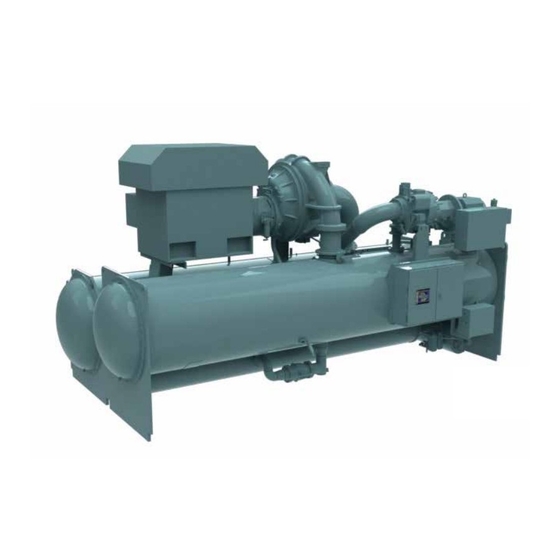
- Page 1 CENTRIFUGAL LIQUID CHILLER WITH ECONOMIZER COMPRESSOR OPERATION AND MAINTENANCE Supersedes: 160.77-O1 (1111) Form 160.77-O1 (1020) MODEL YKEP 2700 - 3200 TON LD15101 R-134a Issue Date: October 22, 2020...
- Page 2 All wiring must be in accordance with Johnson Controls’ published specifications and must be performed only by a qualified electrician. Johnson Controls will NOT be responsible for damage/problems resulting from improper connections to the controls or application of improper control signals.
- Page 3 FORM 160.77-O1 ISSUE DATE: 10/22/2020 CHANGEABILITY OF THIS DOCUMENT In complying with Johnson Controls’ policy for contin- It is the responsibility of rigging, lifting, and operating/ uous product improvement, the information contained service personnel to verify the applicability of these in this document is subject to change without notice.
- Page 4 Your lo- vance rules based rationale delivered by the Johnson cal Johnson Controls Branch can propose a customized Controls Connected Equipment Portal. NOMENCLATURE JOHNSON CONTROLS...
-
Page 5: Table Of Contents
Electrical Controls ............................29 Compressor Motors ............................29 Leak Testing ..............................29 Evaporator And Condenser ..........................29 Oil Return System ............................29 Electrical Controls ............................29 SECTION 4 - TROUBLESHOOTING ........................31 SI Metric Conversion ............................33 Temperature ..............................33 JOHNSON CONTROLS... - Page 6 FIGURE 13 - Motor Starter Temperature and Insulation Resistances ..............26 LIST OF TABLES TABLE 1 - System Pressures ..........................22 TABLE 2 - Refrigerant Charge ..........................24 TABLE 3 - Operation Analysis Chart ........................31 TABLE 4 - Analog Input Ranges (Low Pressure Chillers) ..................33 JOHNSON CONTROLS...
-
Page 7: Section 1 - System Fundamentals
PRIMARY PRIMARY (K7) OPEN-DRIVE COMPRESSOR MOTOR ECONOMIZER (Q3) COMPRESSOR SECONDARY OPEN-DRIVE MOTOR EVAPORATOR SOLID STATE STARTER OIL PUMP PANEL CONTROL PANEL ECONOMIZER ISOLATION CONDENSER VALVE LD15103 FIGURE 1 - YKEP CHILLER MAJOR COMPONENTS (FRONT VIEW) JOHNSON CONTROLS... -
Page 8: Figure 2 - Ykep Chiller (Rear View)
The Primary compressor motor can be equipped with (Figure 4 on Page 8). one of two YORK starters, or optionally, supplied by the customer. Customer-supplied starters must be floor-mounted. LD15104 LD15105 FIGURE 3 - MEDIUM VOLTAGE VSD FIGURE 4 - MEDIUM VOLTAGE SSS JOHNSON CONTROLS... - Page 9 The remaining liquid feeds Motors out of the economizer through a liquid level control valve to the evaporator. YORK YKEP centrifugal chillers utilize air-cooled motors. This means that refrigerant never comes in Heat Exchangers contact with the motor.
- Page 10 Adjustment of the hot gas control valve must steel water baffles are located and welded within the only be performed by a qualified service technician. water box to provide the required pass arrangements. Stub out water nozzle connections with ANSI/AWWA JOHNSON CONTROLS...
- Page 11 The oil heater control capacity. maintains oil temperature above refrigerant tempera- ture while shutdown to avoid foaming. JOHNSON CONTROLS...
-
Page 12: Ykep System Flow Explanation
YKEP SYSTEM FLOW EXPLANATION Step 4. Expansion and Economizer The refrigerant liquid from the condenser is partially The YORK YKEP chiller operates much the same as expanded to a pressure intermediate to the evaporator the YORK YK Single Stage chiller. The only exception and condenser. -
Page 13: Figure 5 - Ykep System Flow Diagram
FORM 160.77-O1 SECTION 1 - SYSTEM FUNDAMENTALS ISSUE DATE: 10/22/2020 LD15103 FIGURE 5 - YKEP SYSTEM FLOW DIAGRAM JOHNSON CONTROLS... - Page 14 FORM 160.77-O1 ISSUE DATE: 10/22/2020 This page intentionally left blank JOHNSON CONTROLS...
-
Page 15: Section 2 - System Operating Procedures
Throughout capacity control, the compressor speed is maintained above the minimum required for the pre- vailing head condition, to avoid surge. Otherwise, the device maintaining capacity is controlled by a pro- LD08647 FIGURE 6 - OIL LIVEL INDICATOR portional-integral-derivative (PID) control based on JOHNSON CONTROLS... -
Page 16: Condenser Water Temperature Control
50 sheets and may be obtained through the nearest recorded for a new unit by more than 4°F (2.2°C). YORK/Johnson Controls office; request the Liquid Chiller Log Sheets (Form 16.44-F7). Weekly An accurate record of readings serves as a valuable ref- 1. -
Page 17: Figure 7 - Liquid Chiller Log Sheets
- refer to Oil Changing Procedure on page * NOTE: These items can be printed by an electronic printer connected to the Microboard and pressing the PRINT key on the Keypad, or automatically using the Data Logger feature. FIGURE 7 - LIQUID CHILLER LOG SHEETS JOHNSON CONTROLS... -
Page 18: Need For Maintenance Or Service
Johnson Controls District Of- During long idle periods, the tightness of fice. Failure to report constant troubles could damage the system should be checked periodically. -
Page 19: Section 3 - Maintenance
5. Open all the dehydrator stop valves. liquid to flow from the evaporator, through the dehy- drator to the compressor sump. COMPRESSOR SOLENOID VALVE CHECK VALVE OIL EDUCTOR BLOCK SOLENOID VALVE DEHYDRATOR STOP VALVE STOP VALVE LD08578 FIGURE 8 - OIL RETURN SYSTEM JOHNSON CONTROLS... -
Page 20: Figure 9 - Charging Oil Reservoir With Oil
2. Immerse the suction connection of the oil charging pump in a clean container of new oil and connect OIL RESERVOIR GAGE LIQUID LEVEL SIGHT LD08579 OIL CHARGING VALVE LD08648 FIGURE 9 - CHARGING OIL RESERVOIR WITH OIL JOHNSON CONTROLS... -
Page 21: Checking System For Leaks
2. Wash off both tube heads and the ends of all tubes by using a soap solution. A continuous buildup of with water. bubbles around a tube indicates a tube sheet leak. JOHNSON CONTROLS... -
Page 22: Conducting An R-22 Pressure Test
75 to 100 PSIG (517 to 690 kPa). To be sure that the concentration of refrigerant has reached all parts of the system test for the pres- ence of refrigerant with a leak detector at an ap- propriate service valve. JOHNSON CONTROLS... -
Page 23: Vacuum Testing
3. Operate the vacuum pump in accordance with rator head drain connection, out the evaporator Vacuum Dehydration in this section until a wet vent connection, into the condenser head drain JOHNSON CONTROLS... -
Page 24: Vacuum Dehydration
By pulling down the system to bring it to atmospheric pressure and the indi- JOHNSON CONTROLS... -
Page 25: Refrigerant Charging
K7 (YDHA119) and BB, BC, BD, B5, B6, B7, B8 Q3 (HF416) 8080 (3665) 7800 (3538) 7520 (3411) 1 Refrigerant charge quantity and weights will vary based on tube count. * Refer to product drawings for detailed weight information. JOHNSON CONTROLS... -
Page 26: Handling Refrigerant For Dismantling And Repairs
The unit must be at positive pressure (no vacuum) during the megging procedure. LD00475 FIGURE 12 - MEGGING MOTOR WINDINGS JOHNSON CONTROLS... -
Page 27: Figure 13 - Motor Starter Temperature And Insulation Resistances
FORM 160.77-O1 SECTION 3 - MAINTENANCE ISSUE DATE: 10/22/2020 LD00476 FIGURE 13 - MOTOR STARTER TEMPERATURE AND INSULATION RESISTANCES JOHNSON CONTROLS... -
Page 28: Compressors
High Oil Temperature (HOT) or Low Oil or nylon brush. DO NOT USE A STEEL BRISTLE Pressure (LOP), change the oil filter element. Exam- BRUSH. A steel brush may damage the tubes. ine the oil filter element for the presence of aluminum JOHNSON CONTROLS... -
Page 29: Electrical Controls
• Corrosion or Rusting. after a new filter is installed, notify the nearest Johnson • Slime and Algae Formation. Controls office to request a Johnson Controls Service Technician. Therefore, proper water treatment is essential to provide for longer and more economical life of the ELECTRICAL CONTROLS equipment. - Page 30 JOHNSON CONTROLS...
-
Page 31: Section 4 - Troubleshooting
Unusually high oil pressure is displayed Pressure Develops High oil pressure. Transducer Replace low or high oil pres- when the oil pressure display key is When Oil Pump defective. sure transducer. pressed when the oil pump is running. Runs JOHNSON CONTROLS... - Page 32 Remove dirt using solvent clogged. Sample and replace. Symptom: No oil pressure registers when pressing Oil Pump Fails Faulty oil pressure transducer. Replace oil pressure trans- OIL PRESSURE display key when oil To Deliver Oil Faulty wiring/connectors. ducer. pump runs. Pressure JOHNSON CONTROLS...
-
Page 33: Si Metric Conversion
(°C), subtract 32° and multiply by 5/9 or 0.5556. Example: (45.0°F - 32°) x 0.5556 = 27.2°C To convert a temperature range (i.e., a range of 10°F) from Fahrenheit to Celsius, multiply by 5/9 or 0.5556. Example: 10.0°F range x 0.5556 = 5.6 °C range JOHNSON CONTROLS... - Page 34 1-800-524-1330 5000 Renaissance Drive, New Freedom, Pennsylvania USA 17349 Subject to change without notice. Printed in USA www.johnsoncontrols.com Copyright © by Johnson Controls 2020 ALL RIGHTS RESERVED Form 160.77-O1 (1020) Issue Date: October 22, 2020 Supersedes: 160.77-O1 (1111)
Need help?
Do you have a question about the York YKEP and is the answer not in the manual?
Questions and answers