Table of Contents
Advertisement
Quick Links
YAES-SA
YAES-DSA
AIR COOLED
SCREW CHILLER
R134a REFRIGERANT
COOLING CAPACITIES
385 kW to 1845 kW
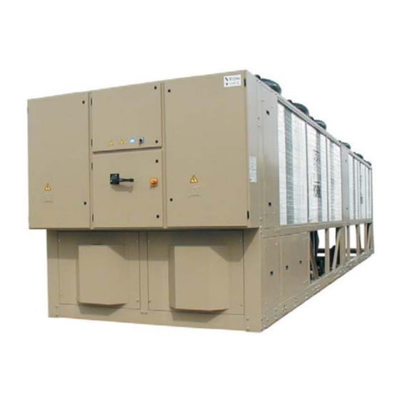
The YAES-SA (QPak-sa) range are single
packaged air cooled chillers. The larger
cooling capacity YAES-DSA (QPak-dsa)
are manufactured in two sections, with
integrated controls, to facilitate transport
and lifting.
There are two product families, standard
units and low sound units, which are
equipped with semi-hermetic twin helical
screw compressors and microprocessor
controls to provide high full and part load
efficiencies and reliable performance.
CONTENTS
Specification
Accessories and Options
Refrigeration Flow Diagram
Operating Limitations
Selection Guide - Cooling
Part Load Factors
Cooling Capacities
Selection Guide - Glycol
Cooling Capacities - Glycol
Desuperheater Data
Physical Data
Sound Data
Electrical Data
Connection Diagrams
Clearances
Dimensions
dsa
dsa
AVAILABLE MODELS, NOMINAL CAPACITIES
and SOUND PRESSURE LEVELS
Cooling Capacity Standard Units
Energy Efficiency Ratio Standard Units EER
Cooling Capacity Sonata Units
Energy Efficiency Ratio Sonata Units
Standard Units
Sound
Sonata Units
Pressure
(Fans at High Speed)
SPL at 10
Sonata Units
metres
(Fans at low Speed)
Cooling Capacity Standard Units
Energy Efficiency Ratio Standard Units EER
Cooling Capacity Sonata Units
Energy Efficiency Ratio Sonata Units
Standard Units
Sound
Sonata Units
Pressure
(Fans at High Speed)
SPL at 10
Sonata Units
metres
(Fans at low Speed)
YAES-DSA
Cooling Capacity Standard Units
Energy Efficiency Ratio Standard Units EER
Cooling Capacity Sonata Units
Energy Efficiency Ratio Sonata Units
Standard Units
Sound
Sonata Units
Pressure
(Fans at High Speed)
SPL at 10
Sonata Units
metres
(Fans at low Speed)
Cooling capacities at 7°C leaving chilled liquid temperature and 35°C ambient.
Sound Pressure level at 10 metres in free field conditions.
The optional low sound version (Sonata) has an acoustically treated enclosure that
contains compressors, valves and piping systems and has specially designed low
sound two speed fans.
YAES-DSA units have a communications link, that must be plugged together,
between the two panels and a mixed liquid sensor that must be installed in the
common leaving liquid pipework from the two evaporators. All units are designed for
roof or ground level locations.
YAES-SA
0405
kW
385
2.8
kW
369
EER
2.6
dB(A)
dB(A)
dB(A)
YAES-SA
0715
kW
723
3.0
kW
694
EER
2.9
dB(A)
dB(A)
dB(A)
1505
kW
1446
3.0
kW
1388
EER
2.9
dB(A)
dB(A)
dB(A)
0475
0545
0575
0645
448
494
540
614
2.8
2.9
2.9
2.7
430
474
518
589
2.6
2.7
2.7
2.6
63
65
65
66
68
56
58
58
59
60
53
54
54
54
56
0785
0905
0985
1075
787
853
922
1030
2.9
2.9
2.9
2.9
756
819
886
989
2.7
2.8
2.8
2.7
68
68
69
69
69
62
62
62
62
63
59
59
58
60
60
1575
1645
1715
1785
1510
1574
1640
1710
2.9
2.9
2.9
2.9
1450
1511
1574
1641
2.8
2.7
2.7
2.7
69
69
69
70
71
63
63
63
64
64
60
60
60
60
61
Doc. No. PC156-100 Rev.3 (01/06)
TABLE 1
0685
661
2.8
635
2.7
67
59
56
1245
1405
1180
1314
2.8
2.8
1133
1261
2.7
2.7
70
70
63
63
60
60
1855
1925
1775
1845
2.9
2.9
1704
1771
2.8
2.8
71
71
64
64
61
61
Page H.1
Advertisement
Table of Contents

Subscribe to Our Youtube Channel
Related Manuals for Johnson Controls YORK YAES-SA


Summary of Contents for Johnson Controls YORK YAES-SA
- Page 1 YAES-SA YAES-DSA AIR COOLED AVAILABLE MODELS, NOMINAL CAPACITIES TABLE 1 and SOUND PRESSURE LEVELS SCREW CHILLER YAES-SA 0405 0475 0545 0575 0645 0685 R134a REFRIGERANT Cooling Capacity Standard Units Energy Efficiency Ratio Standard Units EER COOLING CAPACITIES Cooling Capacity Sonata Units Energy Efficiency Ratio Sonata Units 385 kW to 1845 kW Standard Units...
- Page 2 SPECIFICATION • The gas is compressed in volume and FEATURES BENEFITS increased in pressure before exiting at a designed volume at the discharge Optional acoustic component enclosure and two Low sound operation. end of the rotor casing. Since the intake speed fans and discharge cycles overlap, a High efficiency semi hermetic screw compressors.
- Page 3 Refrigerant Circuits Standard Single Point Power Supply Coils - Fin and tube condenser coils shall An independent refrigerant circuit shall be manufactured from seamless, Connection - Auxiliary Panel 3 Circuit provided per compressor. Each circuit will internally enhanced, high condensing Models use copper refrigerant pipe formed on coefficient, corrosion resistant copper...
- Page 4 Temperature Offset DISPLAY – In Metric (°C and Bar) or • “Out of range” message. English (°F and psi) units. For each • Up to 3 fault shut down conditions. Pulse width modulating (PWM) control is circuit, the following items shall be •...
- Page 5 installation by contractor. Includes all Copper Fin Condenser Coils REFRIGERANT CIRCUIT necessary nuts, bolts, gaskets, etc. Condenser coils are constructed with OPTIONS corrosion resistant copper fins and Flow Switch Accessory provide added protection. Desuperheaters Vapour-proof SPDT, NEMA 4X switch, Factory fitted desuperheaters 10.3 bar DWP, -29°C to 121°C, with...
- Page 6 OPERATING LIMITATIONS TABLE 2 0405 0475 0545 0575 0645 Model YAES-SA Min. Max. Min. Max. Min. Max. Min. Max. Min. Max. 4.5 to 15 Water outlet °C Liquid outlet -12 to 15 Glycol outlet °C temperature Chilled 3 to 10 Temp.
- Page 7 SELECTION GUIDE DATA REQUIRED No correction factors apply therefore, after calculating the flow To select a YORK YAES chiller the following information is rate, the conditions will be as follows: required: Cooling capacity: 723.1 kW 1. Required cooling capacity. Water temperature: 12°C to 7°C (Range = 5°C) Water flow rate: 34.6 I/s...
- Page 8 COOLING CAPACITY FACTORS TABLE 4 AND COMPRESSOR POWER FACTORS - PART LOAD OPERATION Models YAES 0405SA, 0475SA, Compressor Capacity Step Unit Unit 0545SA, 0575SA, 0645SA, 0685SA, Cooling Compressor Compressor No 0715SA, 0785SA, 0905SA & 0985SA Capacity Unit Capacity Step Factor Factor step 4 step 4...
- Page 9 COOLING CAPACITIES - YAES-SA TABLE 6 Page H.9 Doc. No. PC156-100 Rev.3 (01/06)
- Page 10 COOLING CAPACITIES - YAES-SA Page H.10 Doc. No. PC156-100 Rev.3 (01/06)
- Page 11 COOLING CAPACITIES - YAES-SA Page H.11 Doc. No. PC156-100 Rev.3 (01/06)
- Page 12 SELECTION GUIDE - GLYCOL COOLING DATA REQUIRED YAES SAMPLE SELECTION - GLYCOL COOLING To select a YORK YAES glycol chiller, the following information A YAES chiller is required to cool ethylene glycol from 3°C to is required: -2°C having a cooling capacity of 330 kW. Other design conditions applying are: 1.
- Page 13 30% ETHYLENE GLYCOL CAPACITIES - YAES-SA TABLE 11 Page H.13 Doc. No. PC156-100 Rev.3 (01/06)
- Page 14 30% ETHYLENE GLYCOL CAPACITIES - YAES-SA Page H.14 Doc. No. PC156-100 Rev.3 (01/06)
- Page 15 30% ETHYLENE GLYCOL CAPACITIES - YAES-SA Page H.15 Doc. No. PC156-100 Rev.3 (01/06)
- Page 16 30% ETHYLENE GLYCOL CAPACITIES - YAES-DSA Page H.16 Doc. No. PC156-100 Rev.3 (01/06)
- Page 17 OPTIONAL DESUPERHEATER DATA TABLE 12 Capacity Data Model System 1 2 1 2 1 2 1 2 1 2 3 1 2 3 1 2 3 1 2 3 4 1 2 3 4 1 2 3 4 1 2 3 4 1 2 3 4 1 2 3 4 1 2 3 4 DeSuperheater Heat Recovery Capacity (kW) 111 123 136 111 111 123 111...
- Page 18 PHYSICAL DATA - YAES-SA TABLE 13 Model YAES-SA 0405 0475 0545 0575 0645 Refrigerant Circuits Quantity Circuit 1 Refrigerant Charge Circuit 2 Number Type (circuit 1) YTS H-A-E YTS H-A-E YTS I-A-F YTS I-A-F YTS J-A-G Compressors Type (circuit 2) YTS F-A-D YTS H-A-E YTS F-A-D...
- Page 19 PHYSICAL DATA - YAES-SA Model YAES-SA 1075 1245 1405 Refrigerant Circuits Quantity Circuit 1 Refrigerant Charge Circuit 2 Circuit 3 Number Type (circuit 1) YTS L-A-H YTS L-A-H YTS N-A-J Compressors Type (circuit 2) YTS L-A-H YTS L-A-H YTS N-A-J Type (circuit 3) YTS L-A-H YTS L-A-H...
- Page 20 PHYSICAL DATA - YAES-DSA Model YAES-DSA 1505 1575 1645 1715 Refrigerant Circuits Quantity Circuits 1 & 2 Refrigerant Charge Circuits 3 & 4 Number Type (circuit 1) YTS L-A-H YTS M-A-I YTS M-A-I YTS M-A-I Type (circuit 2) YTS L-A-H YTS L-A-H YTS L-A-H YTS L-A-H...
- Page 21 SOUND POWER LEVEL DB TABLE 14 Standard Models Sound Power Level dB Mean Octave Band Levels - Frequency Hz at 10m UNIT TYPE 1000 2000 4000 8000 distance 0405 0475 0545 0575 0645 0685 0715 0785 0905 0985 Standard models without acoustic treatment 1075 1245...
- Page 22 SOUND POWER LEVEL DB Low Sound Sonata Models Sound Power Level Mean Octave Band Levels - Frequency Hz at 10m UNIT TYPE 1000 2000 4000 8000 distance Low Sound Models Fans at High speed 0405 Low Sound Models Fans at low speed Low Sound Models Fans at High speed 0475...
- Page 23 ELECTRICAL DATA TABLE 15 Nominal Running AMPS Maximum Running AMPS Start-up Largest Compressor @ 380 V @ 400 V @360V @ 380 V @ 400 V Amps Star for Star/Delta Without Power Factor Correction Current Amps Models With Optional Power Factor Correction fitted @ 380V @ 400V 0405...
- Page 24 POWER SUPPLY CONNECTION DIAGRAMS MAIN PANEL - ALL MODELS AND AUXILIARY PANEL - YAES-DSA MODELS ONLY Standard Single Point Power Supply One supply to master fused disconnect switch (QCSISDF) or non-fused disconnect switch (QCSISD) with internal power distribution to compressor contactors or fuses, control supply to non-fused disconnect switch (QCSD/ESD) derived internally.
- Page 25 CUSTOMER CONNECTION DIAGRAM (All Models) Note: The Auxiliary Panel is fitted to Models YAES-SA1075, YAES-SA1245,YAES-SA1405 and all YAES-DSA only. 1 PS 2 PS Chilled Liquid Pump Start (Main Panel Only) Unit Run Signal (Main Panel Only) Open on Alarm System N° on Main Panel System N°...
- Page 26 DIMENSIONS Models YAES0405SA and YAES0475SA Page H.26 Doc. No. PC156-100 Rev.3 (01/06)
- Page 27 DIMENSIONS (continued) Models , YAES0545SA, YAES0575SA and YAES0645SA Page H.27 Doc. No. PC156-100 Rev.3 (01/06)
- Page 28 DIMENSIONS (continued) Models YAES0685SA, YAES0715SA and YAES0785SA Page H.28 Doc. No. PC156-100 Rev.3 (01/06)
- Page 29 DIMENSIONS (continued) Models YAES0905SA and YAES0985SA Page H.29 Doc. No. PC156-100 Rev.3 (01/06)
- Page 30 DIMENSIONS (continued) Model YAES1075SA Page H.30 Doc. No. PC156-100 Rev.3 (01/06)
- Page 31 DIMENSIONS (continued) Models YAES1245SA and YAES1405SA Page H.31 Doc. No. PC156-100 Rev.3 (01/06)
- Page 32 DIMENSIONS (continued) Models YAES1505DSA,YAES1575DSA and YAES1645DSA Page H.32 Doc. No. PC156-100 Rev.3 (01/06)
- Page 33 DIMENSIONS (continued) Model YAES1715DSA Page H.33 Doc. No. PC156-100 Rev.3 (01/06)
- Page 34 DIMENSIONS (continued) Model YAES1785DSA Page H.34 Doc. No. PC156-100 Rev.3 (01/06)
- Page 35 DIMENSIONS (continued) Models YAES1855DSA and YAES1925DSA Page H.35 Doc. No. PC156-100 Rev.3 (01/06)
- Page 36 YAES-SA/DSA & AIR COOLED LIQUID CHILLER INSTALLATION, COMMISSIONING, OPERATION AND MAINTENANCE STYLE: REFRIGERANT TYPE: R134a STANDARD and HIGH EFFICIENCY MODELS UNITS WITH THERMOSTATIC EXPANSION VALVES 035L 02672 -100 Rev. 2 (08/05)
-
Page 38: Table Of Contents
035L02672-100 Rev. 2 TABLE OF CONTENTS SUPPLIER INFORMATION INSTALLATION 1.1 Introduction 4.1 Location Requirements 1.2 Warranty 4.2 Location Clearances 1.3 Safety 4.3 Installation of Vibration Isolators 1.4 Responsibility for Safety 4.4 Pipework Connection 1.5 About this Manual 4.5 Water Treatment 1.6 Misuse of Equipment 4.6 Pipework Arrangement 1.7 Emergency Shutdown... - Page 39 035L02672-100 Rev. 2 TROUBLE SHOOTING 8.1 Competent Persons Trouble Shooting Guide 8.2 Sensor Calibration Charts TECHNICAL DATA 9.1 Pressure Drop Graphs 9.2 Operating Limitations 9.3 Physical Data 9.4 Sound Data 9.5 Unit Electrical Data 9.6 System Electrical Data 9.11 9.7 Compressor Electrical Data 9.13 9.8 Control Circuit Electrical Data 9.14...
-
Page 40: Supplier Information
035L02672-100 Rev. 2 SUPPLIER INFORMATION Introduction YORK YAES chillers are manufactured to the highest For warranty purposes, the following conditions must be design and construction standards to ensure high satisfied: performance, reliability and adaptability to all types of air conditioning installations. The initial start of the unit must be carried out by trained personnel from an Authorised YORK Service Centre. -
Page 41: About This Manual
035L02672-100 Rev. 2 About this Manual Structural Support The following symbols are used in this document to alert Structural support of the unit must be provided as the reader to areas of potential hazard. indicated in these instructions. Failure to provide proper support may result in injury to the operator, or damage to A Warning is given in this document to the equipment. -
Page 42: Emergency Shutdown
035L02672-100 Rev. 2 Rotating Parts Emergency Shutdown Fan guards must be fitted at all times and not removed In case of emergency the electrical options panel is unless the main power supply has been isolated. If fitted with an emergency stop device (-QCSD/ESD), this ductwork is to be fitted, requiring the wire fan guards to can be identified as red in colour and sited on a yellow be removed, alternative safety measures must be taken... -
Page 43: Material Safety Data
035L02672-100 Rev. 2 Material Safety Data Refrigerant Data: Safety Data R134a Toxicity Low. In contact with skin Liquid splashes or spray may cause freeze burns. Unlikely to be hazardous by skin absorption. R134a may be slightly irritant and liquid has a degreasing effect. Thaw affected areas with water. - Page 44 035L02672-100 Rev. 2 Refrigerant Data: Safety Data R134a Disposal Best to recover and recycle. If this is not possible, destruction is to be in an approved facility which is equipped to absorb and neutralise acids and other toxic processing products. Fire extinguishing data Non-flammable at atmospheric conditions.
- Page 45 035L02672-100 Rev. 2 Thermal & Acoustic Materials Data Health Hazard & First Aid Toxicity Index <10 to NES713 Issue 3 (1991): Non-hazardous, non-toxic. No first aid necessary. Stability / Reactivity Stable. Handling / Use / Disposal No special handling precautions required. Dispose of according to local laws and regulations governing non-biodegradable non-hazardous solid wastes.
-
Page 46: Product Description
035L02672-100 Rev. 2 1 Fans 2 Condenser 3 Power Section - System 1 4 Control Section 5 Common Input Section 6 Power Section - System 2 7 Aesthetic Panels (option) PRODUCT DESCRIPTION Introduction Compressor The YAES-SA (QPak-sa) range are single packaged air Twin helical semi-hermetic screw compressors, are cooled chillers. - Page 47 035L02672-100 Rev. 2 EVACUATION AND DISCHARGE OIL FILL POINT GAS OUT LIFTING LUGS MOTOR TERMINALS OIL SIGHT GLASS SUCTION GAS IN Refrigerant gas is injected into the void created by the Motor cooling is provided by suction gas from the unmeshing of the five lobed male and seven lobed evaporator flowing across the motor.
-
Page 48: Oil Cooler
035L02672-100 Rev. 2 Capacity Control Condenser The compressors will start at the minimum load position The condenser coils are manufactured from seamless, a n d p r o v i d e a c a p a c i t y c o n t r o l r a n g e f r o m internally enhanced, high condensing coefficient, approximately 30% to 100% per compressor via a valve. -
Page 49: Power And Control Panels
035L02672-100 Rev. 2 Power and Control Panels Standard Single Point Power Supply Connection - Auxiliary Panel YAES-DSA Models All controls and motor starting equipment are factory The common input section contains: wired and function tested. The panel enclosures are designed to IP55 and are manufactured from powder An incoming non-fused disconnect switch for painted galvanised steel. -
Page 50: Accessories And Options
035L02672-100 Rev. 2 The microprocessor also provides low motor current Single Point - System Circuit Breakers protection when it senses a motor current less than Main Panel - All Models, Auxiliary Panel - 4 Circuit 15% FLA. Low motor current protection is activated 9 Models. -
Page 51: Nomenclature
035L02672-100 Rev. 2 Condenser/Exterior Options: Micro Gateway Interface to enable communications with building Un-coated Aluminium Fin Stock control systems using BACnet or MODBUS protocols. Standard condenser coils are constructed using See separate YORK documentation. un-coated aluminium fin stock. Control Panel Display Language English (standard), German, Spanish, French, Gold Coloured Epoxy Coated Fin Condenser Coils Available as an option. -
Page 52: Functional Description
035L02672-100 Rev. 2 2.12 Functional Description OIL COOLER OCLR High Pressure Liquid CONDENSER EVP-3 Optional COMPRESOR High Pressure ZCPR Superheated Vapour EVAPORATOR EVAP Low Pressure Liquid Location of Alternative 2x Relief Valves Low pressure liquid refrigerant enters the evaporator The high pressure oil-free vapour is fed to the air cooled and is evaporated and superheated by the heat energy condenser coil where the heat is removed. - Page 53 035L02672-100 Rev. 2 Page Left Intentionally Blank (08/05)
-
Page 54: Transportation, Handling And Storage
035L02672-100 Rev. 2 TRANSPORTATION, HANDLING AND STORAGE Delivery and Storage Inspection YAES-SA units should be transported on a Remove any transit packing and inspect the unit to S t a n d a r d Ti l t T y p e T r a i l e r ( N O T a ensure that all components have been delivered and that no damage has occurred during transit. - Page 55 035L02672-100 Rev. 2 Lifting using Lugs Typical Lifting Arrangement 2.4 m Units are provided with lifting holes in the base frame which accept the accessory lifting lug set (part number 026L00261-000). The lugs (RH and LH) should be inserted into the respective holes in the base frame and turned so that the spring loaded pin engages into the hole and the flanges on the lug lock behind the hole.
-
Page 56: Installation
035L02672-100 Rev. 2 INSTALLATION Location Requirements On rooftop locations, choose a place with adequate structural strength to safely support the entire operating To achieve optimum performance and trouble-free weight of the unit and service personnel. The unit can be service, it is essential that the proposed installation site mounted on a concrete slab, similar to ground floor meets with the location and space requirements for the locations, or on steel channels of suitable strength. -
Page 57: Installation Of Vibration Isolators
035L02672-100 Rev. 2 Where accumulation of snow is likely, additional height A flow switch must be installed in the customer must be provided under the unit to ensure normal airflow pipework at the outlet of the evaporator and wired to the unit. back to the control panel using screened cable. -
Page 58: Water Treatment
035L02672-100 Rev. 2 Thermometer and pressure gauge connections Water Treatment should be provided on the inlet and outlet connections of the evaporator. The unit performance given in the Design Guide is based on a fouling factor of 0.044 m² °C/kW (0.00025 Drain and air vent connections should be provided ft²hr°F/Btu). - Page 59 035L02672-100 Rev. 2 Recommendations of the Building Services Research Association 1xYAES-SA, 2 Connections per Evaporator 1xYAES-SA, 3 Connections per Evaporator 2xYAES-SA, 2 Connections 2xYAES-SA, 3 Connections per YAES-DSA, 2 Connections per per Evaporator Evaporator Evaporator Double Regulating Valve Binder Point Flow Switch Isolating Valve Strainer...
-
Page 60: Refrigerant Relief Valve Piping
035L02672-100 Rev. 2 Refrigerant Relief Valve Piping Evaporators and oil separators are each protected The unit is not designed to take structural loading. against internal refrigerant over-pressure and fire by No significant amount of weight should be allowed refrigerant relief valves. The pressure relief valve is set to rest on the fan outlet flange, deck assemblies or at the design pressure of the system and has discharge condenser coil module. -
Page 61: Electrical Connection
035L02672-100 Rev. 2 4.10 Electrical Connection Units with Standard Single Point Power Supply Wiring - Non-fused Disconnect Switch (internal The following connection recommendations are power distribution to fuses) intended to ensure safe and satisfactory operation of the unit. Failure to follow these recommendations could Models require one field provided 400 V, 3Ø, 50 Hz + PE cause harm to persons, or damage to the unit, and may supply to the unit with circuit protection. -
Page 62: Output Signals
035L02672-100 Rev. 2 Connect the control supply earth wire to the main 4.12 Output Signals protective earth terminal located in the common input section an M4 lug. All wiring to the voltage free contact terminal block on the relay board requires a supply provided by the Control Circuit Transformer (Primary Voltage customer maximum voltage 254 Vac, 28 Vdc. -
Page 63: System Inputs
035L02672-100 Rev. 2 4.13 System Inputs Remote Set Point Offset - Temperature All wiring to the relay board input signal terminal block Timed closure of suitable contacts connected to (nominal 30 Vdc) must be run in screened cable, with terminals 13 and 17 (PWM contacts) will give remote the screen earthed at the panel end only. -
Page 64: Typical Panel Layout
035L02672-100 Rev. 2 4.14 Typical Panel Layout Compressor Components Control Components Compressor Components Components System Protection Components Components Power Supply Components System Protection Components (08/05) -
Page 65: Power Supply Connection Diagrams
035L02672-100 Rev. 2 4.15 Power Supply Connection Diagrams Main Panel - All Models and AUXILIARY Panel - YAES-DSA Models Only Standard Single Point Power Supply One supply to master fused disconnect switch (QCSISDF) or non-fused disconnect switch (QCSISD) with internal power distribution to compressor contactors or fuses, control supply to non-fused disconnect switch (QCSD/ESD) derived internally. -
Page 66: Customer Connection Diagram (All Models)
035L02672-100 Rev. 2 4.16 Customer Connection Diagram (All Models) Note: The Auxiliary Panel is fitted to Models YAES-SA1075, YAES-SA1245,YAES-SA1405 and all YAES-DSA only. 1 PS 2 PS Chilled Liquid Pump Start (Main Panel Only) Unit Run Signal (Main Panel Only) Open on Alarm System N°... - Page 67 035L02672-100 Rev. 2 This Page Left Intentionally Blank (08/05)
-
Page 68: Commissioning
035L02672-100 Rev. 2 COMMISSIONING Preparation Commissioning of this unit should only be Valves: Open the compressor discharge ball valves carried out by YORK Authorised personnel. fully. Open the compressor motor cooling valves and the liquid line service valves fully and ensure the oil return line ball valves are open. -
Page 69: First Time Start-Up
035L02672-100 Rev. 2 Compressor heaters: Verify the compressor heaters Date & time: Programme the date and time by first are energised. e n s u r i n g th a t t h e C L K j u m p e r J 1 8 o n th e microprocessor board is in the ON position (top two pins). - Page 70 035L02672-100 Rev. 2 Refrigerant flow: When a compressor starts a flow of Subcooling: Check liquid subcooling at steady full liquid refrigerant will be seen in the liquid line sight glass. compressor load only. It is important that all fans are After several minutes operation and providing a full running for the system.
- Page 71 035L02672-100 Rev. 2 This Page Left Intentionally Blank (08/05)
-
Page 72: Unit Operation
035L02672-100 Rev. 2 UNIT OPERATION General Description Normal Running and Cycling The units are designed to work independently, or in Once the unit has been started, all operations are fully conjunction with other equipment via a YORK ISN automatic. After an initial period at minimum capacity on building management system or other automated the lead compressor, the control system will adjust the control system. - Page 73 035L02672-100 Rev. 2 This Page Left Intentionally Blank (08/05)
-
Page 74: Maintenance
035L02672-100 Rev. 2 MAINTENANCE General Requirements Unit status: Press the ‘STATUS’ key on the keypad and ensure no fault messages are displayed (refer to the The units have been designed to operate continuously MBCS Manual for explanation of messages and the provided they are regularly maintained and operated Trouble Shooting section for courses of action). -
Page 75: In Service Inspection
035L02672-100 Rev. 2 Standard Units MAJOR SERVICE SERVICE SCHEDULE MINOR SERVICE All items under Minor Service plus: Unit general: Check thermal insulation. Check main structure. Check vibration isolators. Check paint-work. Refrigerant systems general: Check relief valves. Check solenoid valves. Check fusible plugs. Check for pipework damage. -
Page 76: Trouble Shooting
035L02672-100 Rev. 2 TROUBLE SHOOTING Competent Persons Trouble Shooting Guide PROBLEM POSSIBLE CAUSE ACTION No display on panel — unit will not Mains supply to control system off. Switch on mains supply if safe to do so. operate Emergency stop device off. Check if control panel emergency stop switch and any remote emergency stop devices are in the ‘OFF’... - Page 77 035L02672-100 Rev. 2 PROBLEM POSSIBLE CAUSE ACTION SYS # HIGH DSCH displayed Poor airflow through the condenser Check for airflow restrictions caused by blockages on (High discharge pressure trip) coils. intake faces of air coils. Check for damaged fins/return bends. Check for correct fan operation and direction of rotation.
-
Page 78: Sensor Calibration Charts
035L02672-100 Rev. 2 Sensor Calibration Charts Leaving Chilled Liquid (BLCT) Oil (BOT) Temperature Sensor Ambient Air (BAMB) Temperature Sensor Temperature Resistance Voltage Temperature Resistance °C ohms °C ohms 16598 1.45 55330 14896 1.57 42227 13388 1.69 32650 12047 1.81 25390 10856 1.93 19900... - Page 79 035L02672-100 Rev. 2 Oil (BOP - 400PSIG), Discharge (BDP - 400PSIG), Suction (BSP - 400PSIG) Pressure Transducers 0 - 200 psig Transducer 0 - 400 psig Transducer Pressure Voltage Pressure Voltage psig psig Red wire = 5 V, Black wire = 0 V, White/Green wire = signal Test points : Oil Pressure (BOP):...
-
Page 80: Technical Data
035L02672-100 Rev. 2 TECHNICAL DATA Pressure Drop Graphs Evaporator YAES-DSA Evaporator YAES-SA Model 0405 Model Main Auxiliary 1505 0475 0545 1575 1645 0575 1715 0645 0685 1785 0715 1855 0785 1925 0905 0985 1075 1245 1405 Pressure Drop Calculation Model Pressure Drop[kPa] = 0.1624 x(Flow Rate[l/s] ^ 1.6784 Pressure Drop[kPa] = 0.1203 x(Flow Rate[l/s] ^ 1.7572 Pressure Drop[kPa] = 0.0887 x(Flow Rate[l/s] ^ 1.8179... - Page 81 035L02672-100 Rev. 2 Operating Limitations (Continued) 0685 0715 0785 0905 0985 Model YAES-SA Min. Max. Min. Max. Min. Max. Min. Max. Min. Max. Liquid outlet Water outlet °C 4.5 to 15 temperature Glycol outlet °C -12 to 15 Chilled Temp. spread °C 3 to 10 Liquid...
-
Page 82: Physical Data
035L02672-100 Rev. 2 Physical Data Model YAES-SA 0405 0475 0545 0575 0645 Refrigerant Circuits Quantity Circuit 1 Refrigerant Charge Circuit 2 Number Type (circuit 1) YTS H-A-E YTS F-A-D YTS I-A-F YTS I-A-F YTS J-A-G Compressors Type (circuit 2) YTS F-A-D YTS F-A-D YTS F-A-D YTS I-A-F... - Page 83 035L02672-100 Rev. 2 Physical Data (Continued) Model YAES-SA 1075 1245 1405 Refrigerant Circuits Quantity Circuit 1 Refrigerant Charge Circuit 2 Circuit 3 Number Type (circuit 1) YTS L-A-H YTS M-A-I YTS N-A-J Compressors Type (circuit 2) YTS L-A-H YTS M-A-I YTS N-A-J Type (circuit 3) YTS L-A-H...
- Page 84 035L02672-100 Rev. 2 Physical Data (Continued) Model YAES-DSA 1505 1575 1645 1715 Refrigerant Circuits Quantity Circuits 1 & 2 Refrigerant Charge Circuits 3 & 4 Number Type (circuit 1) YTS L-A-H YTS M-A-I YTS M-A-I YTS M-A-I Type (circuit 2) YTS L-A-H YTS L-A-H YTS L-A-H...
- Page 85 035L02672-100 Rev. 2 Physical Data (Continued) Model YAES-DSA 1785 1855 1925 Refrigerant Circuits Quantity Circuits 1 & 2 Refrigerant Charge Circuits 3 & 4 Number Type (circuit 1) YTS N-A-J YTS N-A-J YTS N-A-J Type (circuit 2) YTS N-A-J YTS N-A-J YTS N-A-J Compressors Type (circuit 3)
-
Page 86: Sound Data
035L02672-100 Rev. 2 Sound Data Standard Models Sound Power Level dB Mean Octave Band Levels - Frequency Hz at 10m UNIT TYPE 1000 2000 4000 8000 distance 0405 0475 0545 0575 0645 0685 0715 0785 0905 0985 Standard models without acoustic treatment 1075 1245... - Page 87 035L02672-100 Rev. 2 Sound Data (Continued) Low Sound Sonata Models Sound Power Level Mean Octave Band Levels - Frequency Hz at 10m UNIT TYPE 1000 2000 4000 8000 distance Low Sound Models Fans at High speed 0405 Low Sound Models Fans at low speed Low Sound Models Fans at High speed...
-
Page 88: Unit Electrical Data
035L02672-100 Rev. 2 Unit Electrical Data Largest Compressor Nominal Running AMPS Maximum Running AMPS Start-up @ 380 V @ 400 V @360V @ 380 V @ 400 V Star for Star/Delta Amps Without Power Factor Correction Current Amps Models With Optional Power Factor Correction fitted @ 380V @ 400V 0405... - Page 89 035L02672-100 Rev. 2 Unit Electrical Data (Continued) Nominal Running AMPS Maximum Running AMPS Start-up Largest Compressor @ 380 V @ 400 V @360V @ 380 V @ 400 V Star for Star/Delta Amps Without Power Factor Correction Current Amps Models With Optional Power Factor Correction fitted @ 380V @ 400V...
-
Page 90: System Electrical Data
035L02672-100 Rev. 2 System Electrical Data Nominal Running Maximum Running Compressor AMPS AMPS Star for Star/Delta @ 380 V @ 400 V @360 @ 380 V @ 400 V Starting Current A Without Power Factor Correction Models @ 380V @ 400V With Optional Power Factor Correction fitted 0405 0475... - Page 91 035L02672-100 Rev. 2 System Electrical Data (Continued) Nominal Running Maximum Running Compressor AMPS AMPS Star for Star/Delta @ 380 V @ 400 V @360 @ 380 V @ 400 V Starting Current A Without Power Factor Correction Models @ 380V @ 400V With Optional Power Factor Correction fitted 1505...
-
Page 92: Compressor Electrical Data
035L02672-100 Rev. 2 Compressor Electrical Data Compressor Running Conditions Largest Compressor Nominal Maximum Star for Star/Delta Power Current Amps Power Current Amps Starting Current A @ 380V @ 400V @360 @ 380V @ 400V Comp's Without Power Factor Correction @ 380V @ 400V Models Motor... -
Page 93: Control Circuit Electrical Data
035L02672-100 Rev. 2 Compressor Electrical Data (Continued) Compressor Running Conditions Largest Compressor Nominal Maximum Star for Star/Delta Power Current Amps Power Current Amps Starting Current A @ 380V @ 400V @360 @ 380V @ 400V Comp's Without Power Factor Correction Models @ 380V @ 400V... -
Page 94: Fan Electrical Data
035L02672-100 Rev. 2 Fan Electrical Data Standard Fans - data per fan Power Running Locked Rotor No. of Fans per System Conditions Conditions System Amps Amps Models @ 400V @ 400V @ 400V 0405 18.6 0475 18.6 0545 18.6 0645, 00575 18.6 0685 18.6... -
Page 95: Connection And Protective Device Data
035L02672-100 Rev. 2 9.10 Connection and Protective Device Data Standard Single Point Power Connection Common Input Section Non-fused Switch Disconnect with Power section System Fuses Power Section(s) Common Input Section System Fuses Max IEC 269-2-1 gG fuse Size Switch Rating Input System Rating... - Page 96 035L02672-100 Rev. 2 Optional Single Point Power Connection Systems 1 and 2: Common Input Section Non-Fused Switch Disconnect with Power Section System Switch Disconnect Fuse or System Circuit Breakers System 3 and 4: Power Section System Switch Disconnect Fuse or System Circuit Breakers Common Input Power Section(s) Section...
- Page 97 035L02672-100 Rev. 2 Optional Multi-Point Power Connection Systems 1 and 2: Common Input Section Terminal Block with Power Section System Switch Disconnect Fuse or System Circuit Breakers System 3 and 4: Power Section System Switch Disconnect Fuse or System Circuit Breakers Common Power Section(s) Input Section...
-
Page 98: Dimensions
035L02672-100 Rev. 2 9.11 Dimensions Models YAES0405SA and YAES0475SA (08/05) - Page 99 035L02672-100 Rev. 2 Models YAES0545SA, YAES0575SA and YAES0645SA (08/05)
- Page 100 035L02672-100 Rev. 2 Models YAES0685SA, YAESSA0715 and YAESSA0785 (08/05)
- Page 101 035L02672-100 Rev. 2 Models YAES0905SA and YAES0985SA (08/05)
- Page 102 035L02672-100 Rev. 2 Model YAES1075SA (08/05)
- Page 103 035L02672-100 Rev. 2 Models YAES1245SA and YAES1405SA (08/05)
- Page 104 035L02672-100 Rev. 2 Models YAES1505DSA,YAES1575DSA and YAES1645DSA (08/05)
- Page 105 035L02672-100 Rev. 2 Model YAES1715DSA (08/05)
- Page 106 035L02672-100 Rev. 2 Model YAES1785DSA (08/05)
- Page 107 035L02672-100 Rev. 2 Models YAES1855DSA and YAES1925DSA (08/05)
-
Page 108: Component Locations
035L02672-100 Rev. 2 9.12 Component Locations 2 System Models 2-FHP1 2-FHP2 1-FHP1 1-FHP2 2-YSBSV 1-YSBSV 2-YOSCV 1-YOCSV 2-BDT 1-BDT 1-ZCPR 2-ZCPR 1-BMP 2-BMP 1-ECH 2-ECH 1-BOP 2-BOP 1-YLIRSV 1-SLO 2-SLO 2-YLIMSV 1-YLIMSV 2-BST2 1-BSP2 1-BST2 2-BSP2 2-YLLSV/2-YEEV 1-YLLSV/1-YEEV - BDP DISCHARGE PRESSURE - XCMTB COMPRESSOR MOTOR TERMINAL BOX... - Page 109 035L02672-100 Rev. 2 3 System Models - BDP DISCHARGE PRESSURE - XCMTB COMPRESSOR MOTOR TERMINAL BOX - BDT DISCHARGE TEMPERATURE - ZCPR COMPRESSOR - SLO SWITCH LOW OIL - BMP MOTOR PROTECTOR - YOCSV OIL COOLING SOLENOID VALVE - BOP OIL PRESSURE - YLIRSV LIQUID INJECTION ROTOR SOLENOID VALVE - BOT...
- Page 110 035L02672-100 Rev. 2 4 System Models 1-FHP1 2-FHP1 1-FHP2 2-FHP2 2-YSBSV 1-YSBSV 2-YOSCV 1-YOCSV 2-BDT 1-BDT 1-ZCPR 2-ZCPR 1-BMP 2-BMP 1-ECH 2-ECH 1-BOP 2-BOP 1-YLIRSV 1-SLO 2-SLO 2-YLIMSV 1-YLIMSV 2-BST2 1-BSP2 1-BST2 2-BSP2 2-YLLSV/2-YEEV 1-YLLSV/1-YEEV 3-YLLSV/3-YEEV 4-YLLSV/4-YEEV 3-BST2 3-BSP2 4-BSP2 4-BST2 - BDP DISCHARGE PRESSURE 4-YLIMSV...
-
Page 111: Point Load And Avm Data
035L02672-100 Rev. 2 9.13 Point Load and AVM Data LOCATION MODEL AVM Colour Grey Grey Green Green Green Green Green Green 0405 Point Load kg 431.4 AVM Colour White White Green Green Green Green Green Green 0475 Point Load kg 472.4 AVM Colour Grey... - Page 112 035L02672-100 Rev. 2 YAES0405SA and YAES0475SA YAES0545SA, YAES0575SA and YAES0645SA YAES 0685SA YAES1075SA-Auxiliary YAES 0715SA and YAES 0785SA-Main YAES 0905SA and YAES0985SA-Main YAES 1245SA and YAES1405SA-Auxiliary YAES 1505DSA, YAES 1575DSA and YAES 1645DSA-Auxiliary YAES 1505DSA, YAES 1575DSA and YAES 1645DSA-Main YAES 1715DSA-Main YAES 1715DS Auxiliary...
-
Page 113: Space Requirements
035L02672-100 Rev. 2 9.14 Space Requirements All Models 2.0 m 1.3 m 1.3 m 2.0 m 2.0 m 2.0 m 2.0 m 2.0 m 1.3 m 2.0 m 3.0 m 2.0 m 2.0 m 2.0 m The recommended clearances and dimensions are the distances between the edge of the units and the architectural enclosure surrounding them. -
Page 114: Spare Parts
035L02672-100 Rev. 2 SPARE PARTS 10.1 Renewal Parts List Details of unit spare parts are given in 035L02778-000. Contact your local YORK Sales and Service Centre for information and please quote the unit model number and serial number. When ordering spare parts, we will require the following information to ensure the correct parts are supplied: Full unit model number, serial number, application and details of the parts required. - Page 115 035L02672-100 Rev. 2 This Page Left Intentionally Blank (08/05)
-
Page 116: Decommissioning, Dismantling And Disposal
035L02672-100 Rev. 2 DECOMMISSIONING, DISMANTLING AND DISPOSAL N e v e r r e l e a s e r e f r i g e r a n t t o t h e If glycol or similar solutions have been a t m o s p h e r e w h e n e m p t y i n g... - Page 117 035L02672-100 Rev. 2 This Page Left Intentionally Blank (08/05)
- Page 118 Italy YORK International ZAO Roca/YORK YORK International Alexeevskaya St. 26, Av. Valdelaparra 47 Unit 4 YORK International 20051 Limbiate (Milan) Office 208 28100 Alcobendas Zealley Estate N. Novgorod, Madrid Greenhill Way Via Manara 2 Spain Kingsteignton Italia Tel: ++39/0299450.1 Tel/Fax: ++7 8312/35 19 03 Tel: ++34 916 624 101 Newton Abbott Fax: ++34 91 662 41 57...
- Page 119 YORK Service and Parts Contact Addresses Austria YORK International YORK International YORK International Widdersdorfer Straße 215 YORK Austria 14 rue de Bel Air 6 Bis rue Chalutier-La-Tanche 50825 Köln Central & Eastern Europe Headquarters B.P.309 56100 Lorient Germany Zetschegasse 3 44473 Carquefou France Tel: ++49/221/498750...
Need help?
Do you have a question about the YORK YAES-SA and is the answer not in the manual?
Questions and answers
Alarm current Mp hpx