
Related Manuals for Johnson Controls York YHAU-C


Summary of Contents for Johnson Controls York YHAU-C
- Page 1 YHAU-C Single Effect Steam-Fired Absorption Chiller Installation, Operation, and 155.34-ICOM2.EN.UL (1219) Maintenance New release Issue Date: 2019-12-27...
-
Page 3: Table Of Contents
Contents Important!............................5 C o n t e n t s General safety guidelines........................5 Safety symbols............................. 5 Changeability of this document......................6 Change bars..........................6 Associated literature........................... 6 Nomenclature............................7 General chiller information and safety..................8 Introduction............................8 About this manual..........................8 Warranty............................... - Page 4 Installation guidelines........................21 Hoisting the machine........................22 Moving the machine on rollers......................22 Jacking the machine.......................... 25 Structural support and installation....................26 Indoor and outdoor installation...................... 26 Electrical.............................. 27 Precautions for use........................... 27 Leak testing............................28 Electrical shock cautions........................28 Vibration and isolation details......................
- Page 5 Stopping the chiller......................... 100 Operation............................ 113 YHAU-C control center........................113 Common items..........................113 Change numeric values........................116 Operating status..........................117 Failure............................... 133 Alarm..............................133 Control parameter........................... 137 Valve operation..........................138 Date and time..........................139 Select language..........................140 Safety switches..........................141 Maintenance..........................
- Page 6 Decrystallization method........................ 150 Indications of crystallization....................151 Decrystallization........................151 Precautions for de-crystallization..................152 Maintenance items.......................... 152 Refrigerant pump manual stop..................154 Purge manual stop and start....................155 Lifespan for various parts......................156 Water quality control........................157 Chemical water treatment......................157 Replacement of water........................
-
Page 7: Important
Important! Read before proceeding! General safety guidelines This equipment is a relatively complicated apparatus. During rigging, installation, operation, maintenance, or service, individuals may be exposed to certain components or conditions including, but not limited to: heavy objects, refrigerants, materials under pressure, rotating components, and both high and low voltage. -
Page 8: Changeability Of This Document
All wiring must be in accordance with Johnson Controls’ published specifications and must be performed only by a qualified electrician. Johnson Controls will NOT be responsible for damage/problems resulting from improper connections to the controls or application of improper control signals. -
Page 9: Nomenclature
Nomenclature YHAU NONE: Single Effect Steam Design Symbol UNIT NOMINAL CAPACITY (RT) York Absorption <Low temp. CHW> Unit : 33.8°F CHW LL : 23.0°F CHW <Generator Design> None :Standard :Special <Model Series name> : 30 - 500RT nominal capacity EXW2S : 630 - 1000RT nominal capacity EXW4S : 1120 - 2000RT nominal capacity YHAU-C Single Effect Steam-Fired Absorption Chiller... -
Page 10: General Chiller Information And Safety
Maintenance. About this manual This manual and any other document supplied with the unit are the property of Johnson Controls, which reserves all rights. This manual may not be reproduced, in whole or in part, without prior written authorization from an authorized Johnson Controls representative. -
Page 11: Quality Assurance
• Only genuine YORK approved spare parts, oils, solutions, chemicals, and refrigerants must be used. • All of the scheduled maintenance operations detailed in this manual must be performed at the specified times by suitably trained and qualified personnel. Failure to satisfy any of these conditions will automatically void the warranty. Refer to Limited Warranty (Form 50.05-NM2) for complete details. -
Page 12: Safety Labels
Safety labels For safe operation, read the instructions first. WARNING: This machine may start automatically without prior warning. CAUTION: Hot surface. WARNING: Safety relief valve may discharge gas or liquid without prior warning. WARNING: Risk of electric shock General attention symbol. WARNING: On isolating the supply it may take up to 300 seconds for the capacitor voltage to fall below 50 V. -
Page 13: Material Safety Data Sheet
Material safety data sheet Material Safety Data Sheets (MSDS) specify proper procedures for handling and working with applicable chemicals, including items such as physical data, toxicity, health effects, first aid, storage, disposal, and spill procedures. YHAU-C Single Effect Steam-Fired Absorption Chiller... -
Page 14: Product Description
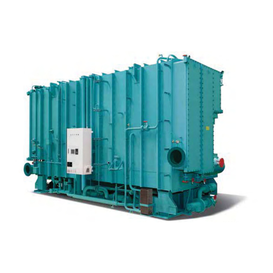
Product description The principle of refrigeration is the exchange of heat and, in absorption liquid chilling, there are four basic heat exchange surfaces: the evaporator, the absorber, the generator, and the condenser. See Figure 1. Like any refrigeration system, an absorption chiller uses evaporation and condensation to remove heat. - Page 15 Figure 1: YHAU-C components Components Cooling Water Inlet Touch Panel Display Control Panel Cooling Water Outlet Chilled Water Inlet Absorber Solution spray pump Evaporator Solution Circulation Pump YHAU-C Single Effect Steam-Fired Absorption Chiller...
-
Page 16: Control Panel
Control panel The absorption chiller comes with a factory mounted and pre-wired control system. The control panel enclosure is equipped with a hinged access door with lock and key. The control panel includes a touch panel showing all system parameters in various languages with numeric data in metric units. -
Page 17: How It Works
How it works The single effect (steam-fired) absorption chiller uses deionized water as the refrigerant and lithium bromide (LiBr) solution as the absorbent. The vapor pressure of the lithium bromide solution is lower than the vapor pressure of the refrigerant. The vapor pressure of the LiBr solution is directly related to the amount of refrigerant (water) present in the solution with the LiBr and the solution temperature. -
Page 18: Two Step Evaporator-Absorber
Two step evaporator-absorber The evaporator and the absorber are split into two sections. This design allows the cycle concentration to be lower than a conventional absorber/evaporator. The lower concentrations mean the unit is more reliable, operates with increased efficiency, and has a lower corrosion potential. -
Page 19: Solution Heat Exchanger
Solution heat exchanger The dilute (weak) LiBr solution leaving the lower absorber section is pumped to the generator section through a solution to solution heat exchanger. It is preheated before entering the generator section. Such preheating of the dilute solution reduces the driving heat source requirement in the generator and also helps to cool down the concentrated (strong) solution before entering the upper absorber section. -
Page 20: Condenser
Condenser The refrigerant vapors leaving the generator condense in the condenser section into liquid refrigerant, using cooling (condenser) water. The liquid refrigerant water is then distributed first in the lower evaporator section. Crystallization All absorption chillers that use LiBr and water as the solution/refrigerant pair are subject to crystallization. -
Page 21: Why Does Crystallization Occur
Why does crystallization occur? The most common reason for crystallization is power failure. If a chiller is running at full load and power is interrupted for a sufficient length of time, the concentrated solution in the high side of the unit eventually cools down. -
Page 22: Handling, Storage, Installation And Reassembly
Handling, storage, installation and reassembly Figure 3: Warning DANGER Rigging and lifting must be done by a professional rigger in accordance with a written rigging and lifting plan. The most appropriate method depends on job specific factors, such as the rigging equipment available and site needs. -
Page 23: Inspection
If the plant room is colder than 50°F, you must have the cold ambient option for outside installation. Inspection The unit must be inspected before customer use by a Johnson Controls Service representative. All damage or possible damage must be reported to the transportation company. For further details, see Commissioning. -
Page 24: Hoisting The Machine
Check the machine compound gauge daily to verify that there is no decline in vacuum and record the vacuum value. If the vacuum is lower than the low limit, contact your nearest authorized Johnson Controls Service Center immediately. c. If the vacuum has dropped as a result of improper machine operation, contact your nearest authorized Johnson Controls Service Center immediately. - Page 25 Figure 4: Hoisting procedure (4 point lifting) Figure 5: Moving the machine on rollers YHAU-C Single Effect Steam-Fired Absorption Chiller...
- Page 26 Figure 6: Fitting tir-rollers to the machine YHAU-C Single Effect Steam-Fired Absorption Chiller...
-
Page 27: Jacking The Machine
Jacking the machine When jacking up the machine, fit a jack in each of the jack-up supports, as shown in Figure 8. Figure 7: Jack-up procedures Operate the front and rear jacks alternately. Do not jack up the machine more than 0.78 in. at a time. Each time the machine is jacked up, adhere it with a suitable crosstie. -
Page 28: Structural Support And Installation
Minimum allowable temperature for outdoor installation is 32°F, provided that the chiller includes the cold ambient option. Outdoor installations will be considered on a case-by- case basis by a Johnson Controls Service Representative YHAU-C Single Effect Steam-Fired Absorption Chiller... -
Page 29: Electrical
Do not place heavy objects on the machine or its control panel; it can fall and injure a worker. Do not climb up the machine without safety harnessing. Contact your local Johnson Controls service office for inspection and maintenance of the machine. Improper inspection and maintenance can cause a machine problem and also injure workers. -
Page 30: Leak Testing
Leak testing When leak testing, verify that the area is correctly ventilated. Failure to do so can result in suffocation. Electrical shock cautions Do not touch the control panel with wet hands. This can cause electric shock. Do not touch the wiring in the control panel. -
Page 31: Vibration And Isolation Details
Vibration and isolation details Before installing the unit, fit rubber vibration isolators to the unit base, as shown in the following image. Use liners to adjust the levelness of the unit. For unit dimensions, see Table 8. Figure 9: Vibration and isolation details Rupture disk and relief piping Note: The ANSI/ASHRAE 15-2001 safety standard code was recently revised to include absorption chiller relief devices. - Page 32 The outer flange of the disk holder has a plastic pipe stub supplied by the factory for shipping purposes. The PLASTIC stub must be removed! Refer to Figure 10. Rupture disk discharge piping material ANSI/ASHRAE 15-2001 calls for the relief piping material to be compatible with the refrigerant in the system.
- Page 33 Figure 11: Location of rupture disk YHAU-C Single Effect Steam-Fired Absorption Chiller...
- Page 34 Table 1: Split shipment dimensions and weight - EXE series Single effect steam absorption chiller (EXE series) Main shell unit Solution heat exchanger unit YHAU-C L1 ft (m) W1 ft (m) H1 ft (m) Weight lb (ton) L2 ft (m) W2 ft (m) H2 ft (m) Weight lb (ton) 30EXET 5.91 (1.8)
- Page 35 Table 2: Split shipment dimensions and weight - EXW series Single effect steam absorption chiller (EXW series) Main shell unit Solution heat exchanger unit YHAU-C L1 ft (m) W1 ft (m) H1 ft (m) Weight lb (ton) L2 ft (m) W2 ft (m) H2 ft (m) Weight lb (ton) 630EXW2ST 18.04 (5.5) 9.02 (2.75) 9.51 (2.9)
- Page 36 Table 3: Nozzle arrangements 30 - 500EXET Nozzle location YHAU-C Chilled water (CHW) Cooling water (COW) Steam Inlet Outlet Inlet Outlet Inlet Outlet Odd pass Odd pass Odd pass 30-500EXET Even pass Even pass Even pass Note: These images are representations of nozzle arrangements. Reference general arrangement drawings for detailed nozzle locations for each specific unit.
- Page 37 Table 4: Nozzle arrangements 630EXW2ST-2000EXW4ST Nozzle location YHAU-C Chilled water (CHW) Cooling water (COW) Steam (SE) Inlet Outlet Inlet Outlet Inlet Outlet Odd pass Odd pass Odd pass 630EXW2ST-2000EXW4ST Even pass Even pass Even pass Note: These images are representations of nozzle arrangements. Reference general arrangement drawings for detailed nozzle locations for each specific unit.
-
Page 38: Hot Insulation And Cold Insulation Procedure
Hot insulation and cold insulation procedure 1. The suggested materials and their thickness for hot insulation or cold insulation are shown in Table 5. 2. Use a bonding agent, iron wire, iron band, and so on, to fix the hot insulation/cold insulation materials. - Page 39 Figure 16: Hot/cold insulation - 30-500EXET models Figure 17: Hot/cold insulation - 630EXW2ST - 2000EXW4ST models YHAU-C Single Effect Steam-Fired Absorption Chiller...
-
Page 40: Technical Data
4.35 psig ~ 43.5 psig (0.3 barg ~ 3 barg) The numbers shown in the previous table are the acceptable ranges for each parameter. Not all combinations are possible. Check with your Johnson Controls Service Center to see if your temperature differential is possible. - Page 41 Table 9: Physical data Radiation Radiation heat Water volume Cold heat loss (with loss (without Chilled Cooling Hot insulation Steam insulation YHAU-C insulation, insulation, water water (abs (gen) area ft (m ambient temp. ambient temp. (evap) and cond) area ft (m ft³...
- Page 42 Figure 18: Load points for EXE and EXW units Table 10: Load points for EXE and EXW units Unit Load point 1 lb (ton) Load point 2 lb (ton) Load point 3 lb (ton) Load point 4 lb (ton) 30EXET 1380 (0.69) 1520 (0.76) 1380 (0.69) 1520 (0.76)
- Page 43 Figure 19: Interior of control panel LD29626 Figure 20: Exterior of control panel YHAU-C Single Effect Steam-Fired Absorption Chiller...
- Page 44 Table 11: Electrical data Main breaker Solution circulation pump Solution spray pump YHAU-C Voltage (V-Ph-Hz) Rated current Frame size AC200 V-3 Ph-50 Hz 25.2 25.2 AC200 V-3 Ph-60 Hz 32 A 160 A 22.2 22.2 AC220 V-3 Ph-60 Hz 24.6 24.6 AC380 V-3 Ph-50 Hz 12.1...
- Page 45 Refrigerant pump Vacuum pump Capacity Consumption SCCR YHAU-C 20.6 20.6 2.06 20.6 30 EXET 0.75 1.12 1.14 1.03 1.05 20.6 20.6 2.06 20.6 40 EXET 0.75 1.12 1.14 1.03 1.05 20.6 20.6 2.06 20.6 50 EXET 0.75 1.12 1.14 1.03 1.05 20.6 20.6...
- Page 46 Solution Main breaker Solution spray pump YHAU-C Voltage (V-Ph-Hz) circulation pump Rated current Frame size AC200 V-3 Ph-50 Hz 25.2 25.2 AC200 V-3 Ph-60 Hz 32 A 160 A 22.2 22.2 AC220 V-3 Ph-60 Hz 24.6 24.6 AC380 V-3 Ph-50 Hz 12.1 12.1 AC380 V-3 Ph-60 Hz...
- Page 47 Refrigerant pump Vacuum pump Capacity Consumption SCCR YHAU-C 20.6 20.6 2.06 20.6 100 EXET 0.75 1.12 1.14 1.03 1.05 20.6 20.6 2.06 20.6 130 EXET 0.75 1.12 1.14 1.03 1.05 0.75 20.6 20.6 2.06 20.6 160 EXET 1.12 1.14 1.03 1.05 20.6 10.8...
- Page 48 Solution Main breaker Solution spray pump YHAU-C Voltage (V-Ph-Hz) circulation pump Rated current Frame size AC200 V-3 Ph-50 Hz 15.6 60.0 11.6 48.0 AC200 V-3 Ph-60 Hz 50 A 160 A 14.8 53.2 11.4 40.6 AC220 V-3 Ph-60 Hz 14.4 59.0 10.6 44.8...
- Page 49 Refrigerant pump Vacuum pump Capacity Consumption SCCR YHAU-C 20.6 12.2 20.6 11.5 20.6 12.2 11.9 11.9 320 EXET 0.75 1.65 12.1 12.5 10.0 11.5 1.45 12.2 12.6 10.1 20.6 12.2 20.6 11.5 20.6 12.2 11.9 11.9 400 EXET 0.75 1.65 12.1 12.5 10.0...
- Page 50 Solution Main breaker Solution spray pump YHAU-CL/CH Voltage (V-Ph-Hz) circulation pump Rated current Frame size AC200 V-3 Ph-50 Hz 26.0 132.0 12.4 42.0 AC200 V-3 Ph-60 Hz 63 A 160 A 25.0 118.0 11.6 46.0 AC220 V-3 Ph-60 Hz 22.8 130.0 11.0 48.0...
- Page 51 Refrigerant pump Vacuum pump Capacity Consumption SCCR YHAU-C 25.6 20.6 17.6 14.0 25.0 20.6 16.7 13.3 26.0 20.6 17.1 13.7 11.9 17.7 14.1 10.7 17.3 13.8 800 EXW2ST 0.75 12.8 17.8 14.3 13.2 17.9 14.3 12.5 16.6 13.3 13.0 17.1 13.7 14.0 17.4...
- Page 52 Solution Main breaker Solution spray pump YHAU-C Voltage (V-Ph-Hz) circulation pump Rated current Frame size AC200 V-3 Ph-50 Hz 38.4 144.0 20.2 72.0 AC200 V-3 Ph-60 Hz 80 A 160 A 36.0 134.0 19.0 70.0 AC220 V-3 Ph-60 Hz 34.0 146.0 18.0 74.0...
- Page 53 Refrigerant pump Vacuum pump Capacity Consumption SCCR YHAU-C 26.0 20.6 25.0 20.0 24.0 20.6 23.4 18.8 26.4 20.6 24.5 19.6 12.5 24.6 19.7 24.2 19.4 1500 EXW4ST 0.75 13.0 25.0 20.0 13.5 25.2 20.1 12.0 23.4 18.7 13.2 24.4 19.5 13.8 24.8 19.9...
- Page 54 Solution Main breaker Solution spray pump YHAU-C Voltage (V-Ph-Hz) circulation pump Rated current Frame size AC200 V-3 Ph-50 Hz 52.6 208.0 38.4 144.0 AC200 V-3 Ph-60 Hz 125 A 160 A 52.0 180.0 36.0 134.0 AC220 V-3 Ph-60 Hz 47.6 197.2 34.0 146.0...
- Page 55 Refrigerant pump Vacuum pump Capacity Consumption SCCR YHAU-C 12.4 42.0 20.6 37.4 29.9 11.6 46.0 20.6 36.0 28.8 11.0 48.0 20.6 36.9 29.5 20.3 36.9 29.5 18.0 36.2 29.0 21.0 37.4 29.9 22.0 37.6 30.1 23.0 35.9 28.7 2000 EXW4ST 0.75 24.0 36.8...
- Page 56 Figure 21: Power wiring Note: The wiring diagrams shown in this manual are suitable for YHAU-CG, YHAU-CW, YHAU- CH/CL, AND YHAU-C chiller models. When the chiller is received at the jobsite, refer to the wiring diagrams that are included with the unit, instead of the diagrams in this manual. Power supply Three-phase, 208/406 V, 60 Hz MCCB...
- Page 57 Model of electromagnetic switch and thermal switch are dependent on pump power. Note 1. According to pump configuration sheet 2. Remove jumper if there is constantly monitoring interlock 3. Do not install ventilation fan for NEMA4/4X enclosure 4. See transformer table 5.
- Page 58 Figure 22: Power supply wiring 24 VAC power supply Noise filter for 24 VDC power supply 115 VAC power 115 VAC power supply control valve control circuit control relay supply control valve WS burner controller LD29586 YHAU-C Single Effect Steam-Fired Absorption Chiller...
- Page 59 24 VDC power supply 24 VDC power supply 24 VDC power supply 24 VDC power supply for PLC & HMI control relay on delay relay CN3 for PLC, CN1 for HMI LD29586a YHAU-C Single Effect Steam-Fired Absorption Chiller...
- Page 60 Figure 23: 24 VDC I/O signal wiring LD29587 YHAU-C Single Effect Steam-Fired Absorption Chiller...
- Page 61 LD29587a If a constantly monitoring cable is used, remove jumper cable. YHAU-C Single Effect Steam-Fired Absorption Chiller...
- Page 62 Figure 24: 115 V input signal wiring 115 VAC 115 VAC Input Input CN1A CN1B LD29588 YHAU-C Single Effect Steam-Fired Absorption Chiller...
- Page 63 115 VAC Input CN1C Solution electrode 33SL2 LD29588a If a constantly monitoring cable is used, remove jumper cable. YHAU-C Single Effect Steam-Fired Absorption Chiller...
- Page 64 Figure 25: PLC output wiring Relay output TB1A LD29589 YHAU-C Single Effect Steam-Fired Absorption Chiller...
- Page 65 Contact output TB1A LD29589a YHAU-C Single Effect Steam-Fired Absorption Chiller...
- Page 66 Figure 26: PLC output wiring Relay output TB1B LD29590 YHAU-C Single Effect Steam-Fired Absorption Chiller...
- Page 67 Standard 5 Contact output TB1A LD29590a YHAU-C Single Effect Steam-Fired Absorption Chiller...
- Page 68 Figure 27: Display /analog input wiring LD29591 YHAU-C Single Effect Steam-Fired Absorption Chiller...
- Page 69 LD29591a YHAU-C Single Effect Steam-Fired Absorption Chiller...
- Page 70 Figure 28: Display/analog input wiring 4 - 20 MA Input LD29611 YHAU-C Single Effect Steam-Fired Absorption Chiller...
- Page 71 LD29611a YHAU-C Single Effect Steam-Fired Absorption Chiller...
- Page 72 Figure 29: Analog output wiring 4 - 20 MA Output LD29612 YHAU-C Single Effect Steam-Fired Absorption Chiller...
- Page 73 Option 3: 4 - 20 MA amplifier for Weishaupt burner 4 - 20 MA output Option 3 LD29616 YHAU-C Single Effect Steam-Fired Absorption Chiller...
- Page 74 Figure 30: Switch input wiring Chilled water Hot water Cooling water High temperature generator Refrigerant tank PF burner flow switch flow switch (option) flow switch (option) pressure & exhaust gas float switch start/stop 69WC1 69WC3 69WC2 temperature switch 33RL1 63SH1, 26EG LD29613 YHAU-C Single Effect Steam-Fired Absorption Chiller...
- Page 75 Figure 31: WS burner control wiring for direct fired chiller WS burner control wiring WS burner WS burner WS burner WS burner start/stop reset alarm combustion LD29613a YHAU-C Single Effect Steam-Fired Absorption Chiller...
- Page 76 Figure 32: Chilled water/hot water temperature switchover wiring for direct fired chiller TC/RTD Input LD29614 YHAU-C Single Effect Steam-Fired Absorption Chiller...
- Page 77 Option 1: Auxiliary heat exchanger for heating for direct fired chiller Relay output TB1B LD29614a YHAU-C Single Effect Steam-Fired Absorption Chiller...
- Page 78 Option 2 VFD wiring drawing (option) 4 - 20 MA Output LD29615 YHAU-C Single Effect Steam-Fired Absorption Chiller...
- Page 79 Figure 33: VFD wiring drawing (option) Option 2: VFDs controls for solution pumps Option 2 VFD1 VFD2 VFD1 VFD2 VFD panel Start/stop Start/stop Control Control ventilation fan LD29615a YHAU-C Single Effect Steam-Fired Absorption Chiller...
- Page 80 Figure 34: Low chilled water control wiring (option) Option 4 LD29617 YHAU-C Single Effect Steam-Fired Absorption Chiller...
- Page 81 Option 4: Low temperature chilled water controls for double effect chiller Please set PLC SW1 and SW2 as shown: LD29617a YHAU-C Single Effect Steam-Fired Absorption Chiller...
- Page 82 Figure 35: Freeze protection wiring (option) Relay output TB1B Option 5 115 VAC power supply heating cable LD29618 YHAU-C Single Effect Steam-Fired Absorption Chiller...
- Page 83 Option 5 Option 5: Freeze protection for low ambient temperature LD29618a YHAU-C Single Effect Steam-Fired Absorption Chiller...
- Page 84 Figure 36: Load limitation wiring (option) Option 6: 0 - 10 V load limit input Option 6 4 - 20 MA input LD29619 YHAU-C Single Effect Steam-Fired Absorption Chiller...
- Page 85 Figure 37: PLC and touch screen communication wiring YHAU-C Single Effect Steam-Fired Absorption Chiller...
- Page 86 Figure 38: PLC and touch screen communication wiring LD29620a YHAU-C Single Effect Steam-Fired Absorption Chiller...
- Page 87 Figure 39: External connection terminal details Ancillary equipment board Absorption chiller control panel (out of scope of supply) (scope of supply) MCCB Power supply 3-phase, 3-wire (See the specification sheet for voltage and frequency) Z3 terminal block Remote start/stop Standard (potential-free level signal) Chilled water pump interlock Cooling water pump interlock Z2 terminal block...
- Page 88 Figure 40: Remote transmission signals Ancillary equipment board Absorption chiller control panel (out of scope of supply) (scope of supply) Z3 terminal block Remote start (potential-free pulse signal) Option Remote stop (potential-free pulse signal) Steam inlet piping (out of scope of supply) Z1 terminal block Steam shut-off valve Steam shut-off valve...
- Page 89 2. Connect to an absorption chiller interlock if necessary. * Indicates a connection is required. a. Operating interlock - *Chilled water operation interlock - Air handling unit interlock b. Cooling water pump interlock - *Cooling water pump interlock c. Normally monitoring interlock - Seismoscope relay - Abnormal room temperature sensor 3.
- Page 90 Figure 41: Signal terminal transition wiring Table 12: Contact specifications Contact specification Max. open/close voltage: AC250 V/DC30 V Absorption chiller control panel - Digital signal Max. open/close current: 2 A/1 Point (resistance load) external output terminal Max. common current: 8 A (resistance load) Analog signal Allowed resistance load: 550 Ohm External - absorption chiller Digital signal Rating voltage/current: DC24 V/7 m A...
-
Page 91: Upper Communication Specification
Figure 42: Sample sound testing for YHAU-C chiller Evaporator side A side B Side (steam inlet side) Background noise Generator side LD19948 Sound measure locations Optional condition Full load operation 77 dbs 79 dbs 79 dbs 78 dbs 72 dbs Note: 1. -
Page 92: Scope Of Delivery
Figure 43: Upper communication system configuration Scope of delivery Johnson Controls scope of delivery for the upper communication system includes the control panels for the upper communication function. The customer is responsible to deliver all other related equipment: concentrator (HUB), installation, wiring, communication program for the central monitoring unit, and so on. -
Page 93: Communication Specification
Table 14: Ethernet interface specification Item Specification LED function Active Blink Data sending/receiving No light No data sending/receiving (Green) Data sending/receiving through Blink Link 10 BASE-T / 100 BASE-TX (Green) No light No connection or successor job failure Communication specification Table 15: Communication specifications Communication protocol Modbus TCP... -
Page 94: User-Created
Table 17: Write command Item Address Content Chiller operation signal 02001 ON at CHILLER OPERATION, PULSE SIGNAL Chiller stop signal 02002 ON at CHILLER STOP, PULSE SIGNAL Steam condensate control valve 00201 0000~1000 unit, 1 unit=0.1% Set point 00203 0050~1000 unit, 1 unit=0.1°F User-Created The following diagrams and tables detail some of the work that must be performed by the customer to ensure that the communication systems work correctly. - Page 95 Figure 44: Connection Detail for D-sub 9pin Table 19: Cable Diagram (RS-422/RS-485) Pin Connection RS-422/RS-485 Pin. No. Signal Name Direction Meaning Input Receive Data A (+) Input Receive Data B (-) Output Send Data A (+) Output Data Terminal Ready A (+) Signal Ground Input Send Possible B (-)
-
Page 96: 2-Wire Type Cable Diagrams
2-Wire Type Cable Diagrams The following is a sample cable diagram for a 2-wire type connection. It uses a GP4000 series (COM2). Figure 45: 2-Wire 1:1 connection with user-created cable Figure 46: 2-Wire n:1 connection with user-created cable YHAU-C Single Effect Steam-Fired Absorption Chiller... -
Page 97: Wire Type Cable Diagrams
4 Wire Type Cable Diagrams The following are sample cable diagrams for 4-wire type connections. They use a GP4000 series (COM2). Figure 47: 4-Wire 1:1 connection with user-created cable Figure 48: 4-Wire n:1 connection with user-created cable YHAU-C Single Effect Steam-Fired Absorption Chiller... - Page 98 The following table contains information about the communication specifications required by the Modbus/RTU. Table 20: Communication specification - Modbus/RTU Communication protocol Modbus/RTU Communication path type RS422/RS485 Data Length: 8 Bit Stop Bit: 1 Bit Parity: EVEN Speed: 9600 bps Connector D-Sub 9pin Function Code Read Coil Status: 01 Read Holding Register: 03...
-
Page 99: Commissioning
Commissioning General guidelines for use Before operation Charge the solution and the refrigerant water if the solution and refrigerant water is in the barrels during the delivery. During commissioning, check the motor’s rotation direction of the solution pump, refrigerant pump, and purge pump: Note: The flow of fluid cannot be seen because the solution and refrigerant pumps are hermetically sealed. -
Page 100: Precautions For The Use Of Steam And Water
The steps and procedures must be performed by a YORK/ Johnson Controls Service person before customer use. All items on the checklist must be completed before charging and initial operation. Failure to do this results in machine malfunction, damage, and/or injury. -
Page 101: Chilled Water Outlet Temperature Controller
• The critical load change condition to prevent an overcooling trip of the chiller is 5% / minimum maximum. Set the steam feed pressure at the inlet of the steam control valve to the specified level. If the pressure is lower than the specification, the result is insufficient performance. Limit the steam pressure fluctuation in the range of the specification value +7/-14 psig. - Page 102 After the review is complete, start the chiller. 1. Navigate to the Control Panel Main screen. 2. Press the OPER. button on the Control Panel to start the chiller. To start the chiller from a remote location, enter the remote start signal. When the chiller starts, the following occurs: •...
- Page 103 Figure 49: Cooling start diagram YHAU-C Single Effect Steam-Fired Absorption Chiller...
- Page 104 Figure 50: Cooling stop diagram YHAU-C Single Effect Steam-Fired Absorption Chiller...
- Page 105 Figure 51: Sequential operation flowchart Note: a. Implement sequential operation of the chilled water pump and the cooling water pump from the chiller. b. If there is one air conditioner, secure interlock for the air conditioner operation (the part indicated by broken lines). c.
- Page 106 Figure 52: Stop the absorption chiller flowchart stop the air conditioner Note: Verify that the air conditioner has stopped after the chiller dilution operation is complete. Otherwise, the chiller can become damaged due to freezing of the chilled water and crystallization of the solution. YHAU-C Single Effect Steam-Fired Absorption Chiller...
- Page 107 9. Detachable flanges are properly installed close to the: a. Valves ..............a. Chilled water box ..........b. Thermowells ............b. Cooling water box ..........c. Plugs ..............c. Steam box ............d. Sight glasses ............JOHNSON CONTROLS YHAU-C Single Effect Steam-Fired Absorption Chiller...
- Page 108 16. The steam supply pressure is stable and within ac- ceptable range ............17. The steam supply temperature does not exceed its saturation temperature ..........NOTES: ________________________________________________________________ ________________________________________________________________ ________________________________________________________________ ________________________________________________________________ ________________________________________________________________ ________________________________________________________________ JOHNSON CONTROLS YHAU-C Single Effect Steam-Fired Absorption Chiller...
- Page 109 9. Press the purge pump OFF button......10. Turn the power switch (MCCB) off......11. Replace or add oil to the purge pump...... NOTES: ________________________________________________________________ ________________________________________________________________ ________________________________________________________________ ________________________________________________________________ ________________________________________________________________ ________________________________________________________________ JOHNSON CONTROLS YHAU-C Single Effect Steam-Fired Absorption Chiller...
- Page 110 18. Check that the steam condensate control valve works automatically according to the chilled water D. Remote Operation Check outlet temperature............ 1. Check that the chiller starts and stops properly using a remote signal ............JOHNSON CONTROLS YHAU-C Single Effect Steam-Fired Absorption Chiller...
- Page 111 ........a. Customer Names: Customer Signature: _______________________________________ Title: _______________________________________ Form Completed by: _______________________________________ ___________ _____________ / ____________ / Year Month NOTES: ________________________________________________________________ ________________________________________________________________ ________________________________________________________________ ________________________________________________________________ ________________________________________________________________ ________________________________________________________________ JOHNSON CONTROLS YHAU-C Single Effect Steam-Fired Absorption Chiller...
- Page 112 Auto. stop temp. °F Purge pump Auto. restart diff. °F Pump Discharge Pressure Purge Amount Solution circulation pump PSIG Standard: 4cc/min or less Solution spray pump PSIG Purge tank Refrigerant pump PSIG Absorber JOHNSON CONTROLS YHAU-C Single Effect Steam-Fired Absorption Chiller...
- Page 113 If differential pressure gauge (DPG) is not available, calculate each pressure drop. If flow meter (FM) is not available, calculate each flow rate as below. [1] = [2] x √[3]/[4] [5]=[6] x √[7]/[8] Waterbox LD20020 JOHNSON CONTROLS YHAU-C Single Effect Steam-Fired Absorption Chiller...
- Page 114 FORM 155.34-CL2 ISSUE DATE: 12/10/2019 PURGE AMOUNT MEASUREMENT DATA SHEET (1/1) User: Model: YHAU - MFG.No.: User's machine code: Measured Date: Measured by: Purge Amount from Purge Line Flame Reaction Test Standard: 4.0 cc/min. or smaller Reaction (Strong/Weak/None) Amount of Gas (P) cc/min Purge Amount from Purge Tank Elapsed time...
- Page 115 Operation YHAU-C control center The YHAU-C Control Center, furnished as standard on each chiller, allows for efficiency, monitoring, data recording, chiller protection, and operating ease. The Control Center is factory-mounted, wired, and tested. It used as a control system for LiBr absorption chillers. The panel is configured with a color TFT Display with buttons that are integrated into the display.
- Page 116 Figure 53: Operating When you press the OPER. button while the chiller is stopped, or STOP while the chiller is operating, a confirmation message appears. Press YES or NO depending on whether you want to continue or cancel your choice. YHAU-C Single Effect Steam-Fired Absorption Chiller...
- Page 117 Figure 54: Stop operation • Screen Name Buttons: Located along the bottom of the screen. These are used to change screens. The selected button lights when it is active. YHAU-C Single Effect Steam-Fired Absorption Chiller...
- Page 118 Change numeric values Many numeric values, such as the set point and the ranges on the Trend screen, can be changed. Here’s how: 1. Touch the number to be changed. A numeric keypad appears. Figure 55: Change numeric values 2. Enter the new value on the keypad. 3.
- Page 119 Main screen The Main Screen displays the equipment status (chiller start or stop, operating, pumps ON or OFF, purge pump ON or OFF, and chilled and cooling water pumps ON or OFF). Also, the operating status of the various modes of chiller operation. Operating status On the upper left of the screen, underneath the LOCAL and REMOTE buttons, is a list of options.
- Page 120 Pump Solution circulating pump, solution spray pump, refrigerant pump, purge pump, chilled water pump, cooling water pump, and hot water pump • Flickers white during operation. Remains black when the pump is stopped. 69WC1 or 69WC2(option) Differential pressure switch of chilled water (69WC1) and cooling water (69WC2) •...
- Page 121 Data screen Figure 56: Data screen The Data Screen displays values showing temperatures, operating hours, operating frequency, data trends and a history of failures, alarms, and time based temperature trends. In the Measured Value section of the Data screen the following display: Chilled Water In Temp.: Temperature of the chilled water measured as it enters the evaporator.
- Page 122 The frequency of failures, alarms, and purges is shown in the Frequency section: • Operation: Displays how many times the chiller has started using the OPER. button or the remote start signal • Start: Displays how many times the heat source (steam) input has started. •...
- Page 123 When maintenance is overdue, the maintenance alarm is activated with the warning “Solution analysis should be done.” When the warning appears, contact your local Johnson Controls Service Center. The Control Panel Parts Replacement section of the screen shows the maintenance interval and current operation hours since the last control panel maintenance.
- Page 124 Solution pump overhaul / refrigerant pump overhaul screen Figure 58: Solution pump overhaul / refrigerant pump overhaul screen The Solution Pump Overhaul section of the screen and the Refrigerant Pump Overhaul section of the screen both indicate the maintenance interval and the current operation hours since the last maintenance.
- Page 125 Trend screen Figure 59: Trend screen To view the Trend Screen, press the Trend button above the History Menu section on the Data screen. This screen graphically illustrates the trend of the temperature and the pressure for the following: • Chilled Water In: Temperature of the chilled water measured as it enters the evaporator •...
- Page 126 Figure 60: Changing display ranges Use the numeric keypad to make the changes. For more information on the procedure, see Change numeric values. To move to another screen, press any of the available buttons along the bottom of the screen. YHAU-C Single Effect Steam-Fired Absorption Chiller...
- Page 127 Hourly operation history screen Figure 61: Hourly operation history screen To view the Hourly Operation History screen, press the Hourly Operation button in the History Menu screen section of the Data screen. The Hourly Operation History screen shows operational information for the last 12 hours and contains the following fields of information: The heading of the screen includes the X time ago and the Measured Date and Time.
- Page 128 In Temp.: Temperature of the cooling water measured as it enters the absorber. Out Temp.: Temperature of the cooling water measured as it leaves the condenser. Ref. Temp.: Temperature of the refrigerant in the evaporator. Abs. Temp.: Temperature of the diluted solution in the absorber. Gen.
- Page 129 Minutely operation history screen Figure 62: Minutely operation history screen To view the Minutely Operation History screen, press the Minutely Operation button in the History Menu section of the Data screen. The Minutely Operation History screen shows operational information for the last 12 minutes and contains the following fields of information: Operation: Operation status of the chiller Ope.
- Page 130 Abs. Temp.: Temperature of the diluted solution in the absorber. Gen. Temp.: Temperature of the concentrated solution in the generator. Gen. Press.: Pressure in the generator. Gen. Concent.: Concentration of the concentrated solution in the generator Ctrl. Valve: Percentage that the valve is open There are two sets of buttons on the right side of the screen.
- Page 131 Failure activation history screen Figure 63: Failure activation history screen You move to the Failure Activation History screen after you press the Failure Activation button in the History Menu screen section. The Failure Activation History screen shows failure information for the last failure and up to six previous failures.
- Page 132 Out Temp.: Temperature of the cooling water measured as it leaves the condenser. Ref. Temp.: Temperature of the refrigerant in the evaporator. Abs. Temp.: Temperature of the diluted solution in the absorber. Gen. Temp.: Temperature of the concentrated solution in the generator. Gen.
- Page 133 Alarm activation history screen Figure 64: Alarm history screen View the Alarm History screen after you press the Alarm button in the History Menu section of the screen. The Alarm History screen shows alarm information for the last alarm and up to six previous alarms. The alarm section contains the following fields of information: Alarm Name: Name or type of alarm Measured Date and Time: Date and time of the alarm...
- Page 134 Out Temp.: Temperature of the cooling water measured as it leaves the condenser. Ref. Temp.: Temperature of the refrigerant in the evaporator. Abs. Temp.: Temperature of the diluted solution in the absorber. Gen. Temp.: Temperature of the concentrated solution in the generator. Gen.
- Page 135 Failure and alarm screen Figure 65: Failure and alarm screen If a failure occurs, the red Failure light lights and the chiller stops. Press the FAIL/ALARM button to access the Failure and Alarm screen for detailed information about the failure. Failure When a failure occurs, an audible alarm sounds (buzzer).
- Page 136 Table 23: Failure list Operation at failure Button label (failure name) Cause occurrence Chilled water pump operation interlock and/or chilled Chilled W. Time Out (Chilled Water water suspension relay was not established in a set Time Out) time while start-up. Not start Cooling W.
- Page 137 Press the ALARM RESET button to reset the to instructions shown in alarm. Maintenance). Manual Purge OFF button was not pressed • • Contact your local Johnson Controls during an automatic purge operation. Service Center. Purge Abnormal • Press the ALARM RESET button to reset the alarm..
- Page 138 Control) for determined period Maintenance). • Contact your local Johnson Controls Service Center. Chilled water inlet temperature sensor, cooling water inlet temperature sensor, and/or absorber temperature sensor detected abnormal value due •...
- Page 139 Setting screen Figure 66: Setting Screen This screen displays control parameters (setting method and each setting parameter), valve operation (control valve mode auto / manual and valve position setting), operation switch (forced dilution, refrigerant pump, purge mode, and manual purge), language (Japanese, English, German, Chinese) and date and time parameters.
- Page 140 Recording Sensor Abnormal Alarm button lights. The target temperature changes to the Local setting. See the following figure for more information. If a failure occurs, automatically move to the failure or alarm screen. For detailed information on how to change an entry in one of these fields, see Change numeric values.
- Page 141 Date and time After you press the Date and Time button, the Date and Time screen displays. Use the following procedure to make changes. Note: To enter the date information, the format is: YYYY / MM / DD. Figure 67: Date and time 1.
- Page 142 Any of these operations can be changed. Select language Press the button to choose the language to be shown in the Control Center. Various languages are available. YHAU-C Single Effect Steam-Fired Absorption Chiller...
- Page 143 Safety switches If any problems occur, the following safety switches stop the absorption chiller safely. Table 25: Safety switches Safety switch name Location Symbol Operation Chilled water differential pressure See Figure 69 69WC1 Operates when the flow rate lowers. switch Solution circulating pump thermal switch Operates when the current rises higher than the...
- Page 144 Failure to do so can cause electric shock and burn. CAUTION Contact your local Johnson Controls Service Office for inspection and maintenance of the machine. Improper inspection and maintenance can cause a machine problem and also injure workers.
- Page 145 Air purge valves and drain valves for chilled water, and cooling water The chiller is equipped with air purge valves and drain valves for chilled water and cooling water. It is equipped with a drain valve for the steam condensate (drain). These valves are used to drain the chilled water, cooling water, and steam condensate (drain).
- Page 146 Capacity check method of vacuum pump For commissioning and regular maintenance, check the capacity of the vacuum pump first according to the following procedure. 1. Check the oil level in the vacuum pump. 2. If the oil is cloudy, it contains water and must be replaced with new oil. 3.
- Page 147 Figure 68: Location of manual valve in purge system Purging operating valve for purge tank line Purging operating valve for absorber line Purge main valve Manual method to purge air directly from absorber When the chiller operates at a lower capacity than usual for a long period of time or when it restarts after a power failure, the absorber can contain non-condensable gases.
- Page 148 CAUTION Make sure that the valve is completely open. 8. Continue to purge for 2 to 3 hours. 9. Close valve V13 and V16. 10. Press the Manual Purge OFF button. The vacuum pump stops. For information on how to set up an automatic purge, see Automatic method to purge non- condensable gas from purging tank.
- Page 149 Automatic method to purge non-condensable gas from purging tank This chiller has an automatic purge system. The vacuum pump starts and stops by detecting the pressure inside the purge tank. 1. Set the valves in accordance with purge pattern D shown in Figure 69. 2.
- Page 150 Figure 69: Process and instrumentation diagram for EXW series chiller YHAU-C Single Effect Steam-Fired Absorption Chiller...
- Page 151 Figure 70: Process and instrumentation diagram for EXE series chiller Valve operation/location Purging pattern Operation V10, V11 V13, V16 Check capacity of vacuum pump – × × × Preparation × × × Direct purging from absorber Starting purging × × Preparation ×...
- Page 152 When refining refrigerant, operate the absorption chiller under a low load (50% or less) for higher refining efficiency. Note that the refrigerating capacity is dramatically reduced during the refrigerant refining operation. 1. Remove the cap of the refrigerant manual blow valve. Note: For the location of the refrigerant manual blow valve, see Figure 70.
- Page 153 If the crystals cannot be melted by the following procedure, notify your local Johnson Controls Service Center immediately. Indications of crystallization • The refrigerating capacity goes down. The liquid level in the absorber drops. Cavitation noise comes out of one or more of the solution pumps.
- Page 154 Maintenance items Maintenance and inspection items along with standard inspection periods are shown in the next table. For details, contact your local Johnson Controls Service Center. Inspection frequency can be adjusted according to the actual operating conditions. Table 27: Maintenance and inspection...
- Page 155 Table 27: Maintenance and inspection Task Contents Frequency Scope After the replacement of the lubricant oil for the Check of Vacuum Pump vacuum pump, be sure to pull the pulley belt and Monthly check the smooth motion of the pulley. Check the outside of the machine for damage (such as leakage for chilled water and cooling Appearance check...
- Page 156 Note: 1. C = Customer and S = Johnson Controls Service 2. Note: *If water quality analysis indicates necessity. Refrigerant pump manual stop The refrigerant pump can be stopped manually for maintenance purposes. It can be stopped even while the chiller operates.
- Page 157 Note: After the maintenance of the refrigerant pump is complete, press the Refrigerant Pump Auto button. Continued operation in the stop mode can cause damage to and failure of the chiller. Purge manual stop and start Before you begin: The purge can be started or stopped manually. Navigate to the Control Panel Setting screen.
- Page 158 Lifespan for various parts The replacement period for some parts are shown in the following table. (The following periods are shown for reference only. The replacement period can be changed according to the actual environment, frequency of use, weather and so on. Other parts can need to be replaced if used incorrectly.) Table 28: Lifespan of common parts Part name...
- Page 159 Table 28: Lifespan of common parts Part name Lifespan of common parts Remarks Rubber hose set for purge line Every 18,000/Hr Oil for purge pump Every month Refrigerant tank float switch Every 60,000/Hr Water quality control Use the following guidelines ensure of the highest water quality control standards: •...
- Page 160 If the flow speed reaches 11.6 to 16.3 ft/s, the tubes can erode. When changing the flow rate, contact your local Johnson Controls Service Center. If the water supply rate is adjusted at the inlet side of the heat exchanger (evaporator, condenser, and absorber), the eddy current at the inlet can corrode the tube.
- Page 161 If it is likely that the temperature can drop lower than 32°F, provide a heater for the machine. If a heater is not possible, contact your local Johnson Controls service center for further information. For details on the wet storage method, see Table 29.
- Page 162 If it is not possible to protect the machine, fill the interior with N2 to minimize the amount of air leakage. For details, contact your local Johnson Controls service center. Table 29: Wet storage method Part Storage method Notes Chilled water...
- Page 163 Table 31: Tendency of generation of scales and corrosion by quality of cooling water Quality of cooling General tendency water Scale and its color Corrosion and its color Hard scales are Dark brown - Bad corrosion of iron and Low water PH generated and iron pale greenish copper...
- Page 164 Table 32: Chilled water and cooling water quality control (maximum concentrations) (3) (4) Cooling water system Non- Chilled water system Tendency Circulating type circulating (1) (6) Element water Circulating Replenish Replenish Circulating Passing Scale water (20 °C Corrosion water water forming water water...
- Page 165 6. The 15 items previously shown are representative factors in corrosion and scale formation. Note: The manufacturer suggests the installation of expansion joints for the chilled water and cooling water connections. Figure 72: Chilled water and cooling water system Table 33: Steam drain quality control Component Standard value 7.5 ~ 8.5...
- Page 166 Figure 73: Steam and drain system YHAU-C Single Effect Steam-Fired Absorption Chiller...
- Page 167 Figure 74: Duhring diagram / PTX chart (°F) YHAU-C Single Effect Steam-Fired Absorption Chiller...
- Page 168 Figure 75: Duhring diagram / PTX chart (°C) YHAU-C Single Effect Steam-Fired Absorption Chiller...
- Page 169 Figure 76: Specific gravity - concentration (°F) YHAU-C Single Effect Steam-Fired Absorption Chiller...
- Page 170 Figure 77: Specific gravity - concentration (°C) YHAU-C Single Effect Steam-Fired Absorption Chiller...
- Page 171 If the cause is not clear, using the countermeasure cannot repair the problem, or if the chiller seems to have a serious problem, contact your local Johnson Controls Service Center immediately. If the chiller stops because of a problem, wait until the chilled water pump, cooling water pump, and chiller unit stop completely, then verify the following items.
- Page 172 (absorber). Heat exchange tube is dirty (Chilled water, cooling water). Solution is crystallized. Contact your local Johnson Controls Service Office. Corrosion inhibitor is worn. Air leaks in absorption chiller. Table 35: Chilled water overcooling or refrigeration overcooled...
- Page 173 Pump is damaged by cavitation caused by low liquid level. Thermal switch is not set correctly. Internal cycle control valve is not set Contact your local Johnson Controls Service Office. correctly. Filter in the pump is clogged. Solution is crystallized.
- Page 174 1-7 in the following table. If the cause of the trouble is something other than numbers 1-7, it can be one of number 8-14. In this case, contact your local Johnson Controls Service Center immediately. Table 43: Troubleshooting performance issues...
- Page 175 When the Purge Abnormal button lights on the Failure and Alarm screen, the vacuum pump needs to be disassembled for inspection. Contact your local Johnson Controls Service Center. The entire purge line must be inspected if the Abnormal Purge Freq. button on the same screen lights, or if the vacuum level of the purge line does not reach the specified level during the vacuum pump capacity check.
- Page 176 Table 46: Insufficient vacuum levels Item Cause Countermeasure Purge pump trouble Contact your local Johnson Controls Service Office. Deterioration of vacuum pump oil Replace the vacuum pump oil. Incorrect operation of purging line switching when Purge procedure. Confirm the valves are open or vacuum pump capacity was checked.
- Page 177 Actions to take against power failure If the main power fails, follow the steps displayed in this chart. Figure 78: Actions to take against power failure YHAU-C Single Effect Steam-Fired Absorption Chiller...
- Page 178 Figure 79: Troubleshooting sequence flow chart YHAU-C Single Effect Steam-Fired Absorption Chiller...
- Page 179 Decommissioning, dismantling, and disposal Unless otherwise indicated, the operations described in the following list can be performed by any correctly trained maintenance technician. 1. Isolate all sources of electrical supply to the unit, including any control system supplies switched by the unit. Make sure that all points of isolation are secured in the off position. 2.
- Page 180 © 2019 Johnson Controls. All rights reserved. All specifications and other information shown were current as of document revision and are subject to change without notice. www.johnsoncontrols.com...
Need help?
Do you have a question about the York YHAU-C and is the answer not in the manual?
Questions and answers