Table of Contents
Advertisement
Quick Links
ASSEMBLY AND INSTALLATION
S.R. SMITH VORTEX SLIDES ARE MANUFACTURED FOR INSTALLATION
AND USE ON INGROUND SWIMMING POOLS ONLY. THE VORTEX IS
NEVER TO BE INSTALLED AND USED ON ABOVEGROUND POOLS,
ONGROUND POOLS, HOUSEBOATS, BOAT DOCKS, FLOATING DOCKS
OR PLATFORMS OR OTHER BODIES OF WATER SUCH AS LAKES,
PONDS, RIVERS, ETC.
SRS AUSTRALIA, PTY LTD
12 Enterprise St
Richlands QLD 4077
Australia
Phone 07 3812 2283 • Fax 07 3812 1187
www.srsmith.com/au
06-199
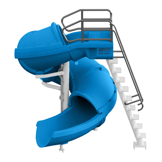
VORTEX
INSTRUCTIONS
S.R. SMITH, LLC
CORPORATE HEADQUARTERS
P.O. Box 400 • 1017 S.W. Berg Parkway
Canby, Oregon 97013
USA
Phone (503) 266 2231 • Fax (503) 266 4334
www.srsmith.com
MAY 19
Advertisement
Table of Contents

Related Manuals for S.R.Smith VORTEX


Summary of Contents for S.R.Smith VORTEX
- Page 1 ASSEMBLY AND INSTALLATION INSTRUCTIONS S.R. SMITH VORTEX SLIDES ARE MANUFACTURED FOR INSTALLATION AND USE ON INGROUND SWIMMING POOLS ONLY. THE VORTEX IS NEVER TO BE INSTALLED AND USED ON ABOVEGROUND POOLS, ONGROUND POOLS, HOUSEBOATS, BOAT DOCKS, FLOATING DOCKS OR PLATFORMS OR OTHER BODIES OF WATER SUCH AS LAKES, PONDS, RIVERS, ETC.
-
Page 2: Table Of Contents
MAIN SECTION AND SLIDE RUNWAY PARTS LIST ................. 7 Tools Required ............................8 Gasket Installation ............................. 8 VORTEX MAIN SECTION AND SLIDE RUNWAY ASSEMBLY INSTRUCTIONS ........9 VORTEX CLOSED FLUME PARTS LIST ....................14 VORTEX CLOSED FLUME ASSEMBLY INSTRUCTIONS ................ 15 VORTEX OPEN FLUME PARTS LIST ....................... -
Page 3: Introduction
DANGER – FAILURE TO FOLLOW THESE WARNINGS, INSTRUCTIONS, AND THE OWNER’S MANUAL MAY RESULT IN SERIOUS INJURY OR DEATH. THE VORTEX IS DESIGNED AND MANUFACTURED FOR INSTALLATION AND USE ON INGROUND SWIMMING POOLS ONLY. DO NOT INSTALL THIS SLIDE ON ABOVEGROUND POOLS, HOUSEBOATS, BOAT DOCKS, FLOATING DOCKS OR PLATFORMS, OR OTHER BODIES OF WATER SUCH AS LAKES, PONDS, RIVERS, ETC. -
Page 4: Installed Vortex Structural & Installation Checklist
6. Observe the position of the exit of the slide as shown on pages 41 and 41. MAINTENANCE INSTRUCTIONS 1. Periodically inspect the vortex to assure there are no worn parts and that all hardware is properly tightened. Replace any hardware which exhibits rust or corrosion. -
Page 5: Assembled Vortex With Stairs Layout
ASSEMBLED VORTEX WITH STAIRS LAYOUT FIGURE A... - Page 6 ASSEMBLED VORTEX WITH LADDER LAYOUT FIGURE B...
-
Page 7: Main Section And Slide Runway Parts List
MAIN SECTION AND SLIDE RUNWAY PARTS LIST ITEM NO. PART NO. DESCRIPTION QTY. KIT A KIT B KIT C KIT A 66-209-177 FLUME HARDWARE KIT 1 ea. KIT B 66-209-178 HALF FLUME HARDWARE KIT 1 ea. KIT C 66-209-311 UNIVERSAL SPARE HARDWARE KIT 1 ea. -
Page 8: Tools Required
Tools Required 4 Irwin Quick Grip™ 18” XP Bar Clamps Ratchet Handle 9/16” Socket (Deep) Power Drill 9/16” Wrench PVC Pipe Primer & Glue 3/4" Socket or Wrench (Deep) Anti-Seize 7/32” Allen Wrench (Deep) Saw to Cut PVC Pipe Phillips Head Screwdriver Knife Roto-Hammer Drill Level... -
Page 9: Vortex Main Section And Slide Runway Assembly Instructions
VORTEX MAIN SECTION AND SLIDE RUNWAY ASSEMBLY INSTRUCTIONS 1. Insert all five of the Branch Arms (4) into the Main Support (5). Carefully slide the arms into the support sockets to ensure the powder coating is not damaged. Align the holes in the branch arms with the slots in the main tube support and fasten them as shown in Figure D. - Page 10 Note: Before working with the flume pieces, cover the concrete with cardboard or carpet to prevent scratching the plastic slide components. The order of assembly is important! All of the Runway Sections (2) are labeled at both ends indicating the order in which they need to be assembled.
- Page 11 4. Place the assembled Exit Flume (3) and Runway Section (2) over the first Branch Arm (4). Attach the slide sections to the first branch arm as shown in Figure G. The required hardware is as follows: 3/8”- 16 x 5-1/2” Hex Head Cap Screw (8), 3/8” Flat Washer (18), 3/8” Nylon Washer (20), 3/8” Flat Washer (18), 3/8”...
- Page 12 6. Fasten the sides of Runway Section (2) labeled B2 to the previously assembled runway section using the fasteners shown in Figure E. Then attach the bottom of Runway Section (2) to the branch arm using the fasteners shown in Figure G. FIGURE I 7.
- Page 13 9. Fasten the bottom of the Entrance Section (1) to the branch arm, as shown in Figure I. The screws will be screwed into the threaded inserts in the Entrance Section (1). The hardware required is as follows: 3/8”-16 x 3-1/2” Button Head Cap Screw S/S (10), 3/8” Lock Washer S/S (21), 3/8” Flat Washer S/S (22), and a 3/8”...
-
Page 14: Vortex Closed Flume Parts List
5-139 4 ea. 3/8” RUBBER WASHER ● 05-626 4 ea. ● 05-14-151 VORTEX SPACER, 5/8 X 2.75 304 SS TUBING 12 ea. 3/8” CUSTOM FLAT WASHER S/S ● 05-14-150 24 ea. Visit srsmith.com for hardware kit and replacement part information. -
Page 15: Vortex Closed Flume Assembly Instructions
VORTEX CLOSED FLUME ASSEMBLY INSTRUCTIONS 1. Assemble the four remaining Runway Section (2) pieces. Order of assembly is important. The end of each runway section is labeled and must be assembled to the runway section with the same label. Assemble the lower two sections. They are labeled T1 on their mating ends. Fasten the sections together using the screw hole locations located at the sides and the top of the Runway Section (2) as shown in Figure K. - Page 16 2. Make sure the gasket is in place. Slide all four assembled parts of the cover flume up the slide from the bottom. You will need 3-4 people to assist in getting it positioned correctly. Attach the hardware at the top of the runway as shown in Figure L. The hardware required for this step is as follows: 3/8”-16 x 6”...
- Page 17 3. Fasten the top and bottom runway parts together along the inside curve as shown in Figure 13. The hardware required for this step is as follows: a 3/8”-16 x 8-1/2” Hex Head Cap Screw S/S (14), 3/8” Flat Washer S/S (21), 3/8” Rubber Washer (27), 3/8” Flat Washer S/S (21), 3/8” Lock Washer S/S (25), 3/8”...
-
Page 18: Vortex Open Flume Parts List
● 5-151 19 ea. 3/8” HEX NUT S/S ● 5-139 19 ea. ● 05-14-151 VORTEX SPACER, 5/8 X 2.75 304 SS TUBING 12 ea. 6-690-4 CURVE SECTION RISER 4 ea. 3/8” x 4-1/2” BHCS S/S ● 5-513 6 ea. ●... -
Page 19: Vortex Open Flume Assembly Instructions
VORTEX OPEN FLUME ASSEMBLY INSTRUCTIONS 1. Assemble the four Curve Section Riser (39) pieces. Fasten the two sections together using the two bolt locations through the side of the parts as shown in Figure N. The hardware required for the two side locations is as follows: 3/8”-16 x 4-1/2”... - Page 20 2. Make sure the gasket is in place. 3. Slide all four pieces of the open flume up the slide from the bottom. Attach the hardware at the top of the runway as shown in Figure O. Use the Riser Bracket (41) to secure the Open Flume Risers to the Runway.
- Page 21 6. Working from the top to bottom, fasten the Risers to the Runway Flumes along the outside edge as shown in Figure P. The required hardware is as follows: 1-1/4” Plastic Plug (74), 3/8”-16 x 5” Button Head Cap Screw S/S (12), 3/8”...
-
Page 22: Vortex Stairway Parts List
VORTEX STAIRWAY PARTS LIST ITEM NO. PART NO. DESCRIPTION QTY. KIT D KIT D 66-209-2S STAIRWAY HARDWARE KIT 1 ea. 1/2” x 3-3/4” CONC. ANCHOR WITH HARDWARE (SEE PAGE 7) ● 5-523-SS 6 ea. 3/8” x 3-1/2” BHCS S/S (SEE PAGE 7) 5-250 2 ea. -
Page 23: Vortex Stairway Assembly Instructions
VORTEX STAIRWAY ASSEMBLY INSTRUCTIONS 1. The nuts and washers will need to be removed from the lower guardrail connections, so the stair support angle bracket can be slipped up under the entrance flume with these screw threads feeding through the slots in the angle bracket. Move the Main Stair Support (61) into place as shown in Figure Q. - Page 24 6. Install the hardware through the holes on the front face of the Main Stair Support angle bracket (61) and the Entrance Flume (1), See Figure R. The required hardware is as follows: 3/8” x 3-1/2” Button Head Cap Screw (10), 3/8” Flat Washer (21), 3/8”...
- Page 25 8. Place the Outside Stair Bracket (51) in line with the two holes on the inside of the Main Stair Support Angle Bracket so that it is closest to the support tube. See Figure S. Use the following hardware to attach the bracket to the main stair support: 1/2” x 1-1/2” Hex Head Bolt (44), 1/2”...
- Page 26 11. Move the Middle Stair Support (62) into place as shown in Figure T. Align the holes in the Middle Stair Support bracket with the holes in the stair brackets. 12. Attach both sides of the Middle Stair Support to the stair brackets as shown in Figure T. The required hardware is as follows: 1/2”...
- Page 27 14. Place the bottom outside Stair Bracket (53) in line with the two holes on the outside Stair Bracket so that it is inside the stair bracket, as shown in Figure U. Use the following hardware to attach the bracket to the Main Stair Support: 1/2” x 1-1/2” Hex Head Bolt (44), 1/2”...
- Page 28 16. Place the Step Bracket Anchor (43) inside the two Bottom Stair Brackets and align the holes in the flanges as shown in Figure V. Use the following hardware to attach both sides of the Step Bracket Anchor (43) to the Bottom Stair Brackets: 1/2”...
- Page 29 17. Install Stair Steps (57) on all of the steps except for the ones where handrail brackets will be attached. Align the pre-drilled pilot holes in the Stair Steps (57) with the holes on each side of the stair brackets as shown in Figure W. Use the following hardware to attach the Stair Steps (57) to the brackets: 5/16”...
- Page 30 18. Install the handrails using enough hardware to hold them in place. Make sure that the Step Bracket Anchor (43) and the base plate of the Middle Stair Support (62) are flat against the concrete deck. 19. Mark the hole locations for the concrete anchors. Unfasten the stair assembly from the Main Stair Support (61), and move it aside.
- Page 31 20. Install the Platform Steps (55 and 56) and the Bottom Step (58). Use the following hardware to attach the stair steps through the Handrail brackets: 5/16” x 2-1/2” Socket Head Cap Screw (63), 5/16” Flat Washer (48), 5/16” Nylon Washer (46), 5/16” Flat Washer (48), 5/16”...
-
Page 32: Vortex Ladder Parts List
VORTEX LADDER PARTS LIST ITEM NO. PART NO. DESCRIPTION QTY. 1/2” x 3-3/4” CONC. ANCHOR WITH HARDWARE 5-523-SS 4 ea. 3/8” x 3-1/2” BHCS S/S 5-250 2 ea. 1/2” LOCK WASHER S/S 05-14-115 4 ea. 1/2” NYLON WASHER 05-616 4 ea. -
Page 33: Vortex Ladder Assembly Instructions
VORTEX LADDER ASSEMBLY INSTRUCTIONS FIGURE Z 1. Move the Ladder (64) into place as shown in Figure AA. Align the holes in the ladder angle bracket with the holes in the entrance section. To ensure proper alignment of the assembly, temporarily place bolts through the mounting holes in the ladder and the entrance section. - Page 34 3. Move the ladder aside, before drilling the 1/2”Ø x 4” deep holes for the concrete anchors. 4. Move the ladder back over the holes and against the entrance section of the slide, with the HDPE Gasket (73) between the base plate and deck. Then follow the instructions on page 41 for inserting the concrete anchors into the deck.
- Page 35 5. Fasten the hardware through the holes on the front face of the Ladder angle bracket as shown in Figure CC. The required hardware is as follows: 3/8” x 3-1/2” Button Head Cap Screw (10), 3/8” Flat Washer (24), 3/8” Nylon Washer (23), 3/8” Flat Washer (24), 3/8” Lock Washer (25), 3/8” Hex Nut (26).
-
Page 36: Vortex Warning Sign Parts List
ITEM NO. PART NO. DESCRIPTION QTY. 05-623 SLIDE LARGE DECK FLANGE WITH HARDWARE 1 ea. 06-369 VORTEX SLIDE RULES SIGN (NOT SHOWN) 1 ea. 5/16”x 2-3/4” CONCRETE ANCHOR WITH HARDWARE 05-162 4 ea. 5/16” LOCK WASHER 800-1110 1 ea. 4-409 VORTEX WARNING SIGN POST 1 ea. -
Page 37: Vortex Water System Parts List
VORTEX WATER SYSTEM PARTS LIST Item Number Description Quantity 1-1/2”Ø “CLIC TOP” PIPE CLAMP 5 ea. #10-32 x 2” PANHEAD SCREW (PRE-INSTALLED IN MAIN SUPPORT) 5 ea. 1-1/2”Ø x 3” SCH 80 PIPE 1 ea. 1-1/2”Ø 45º SCH 80 ELBOW 1 ea. - Page 38 2. Assemble the three PVC components together in the order shown in Figure FF. Do not glue any of the parts together at this point. The plumbing system should be fully assembled first to ensure correct orientation before the parts are glued together. 3.
- Page 39 5. Connect the 1-1/2ӯ PVC Flex Hose (34) to the water supply. Then run the other end up through the lower 1-1/2ӯ Pipe Clamps (28). 6. Attach the 1-1/2ӯ PVC Ball Valve (33) as shown in Figure GG. FIGURE GG...
- Page 40 10. The Vortex is designed to connect to a 1-1/2”Ø water supply line. Plumb the water supply from the pool return line with a 1-1/2”Ø PVC pipe. Position the water supply “stub up” at the base of the slide’s ladder, where the lower end of the 1-1/2”Ø...
-
Page 41: Concrete Wedge Anchor Mounting Instructions
“Manufacturer’s Placement Instructions” noted on pages 41 and 41. The Vortex slide must be anchored into a concrete pad that is a minimum of 8” thick. With the slide in its proper location, center punch or otherwise mark through the mounting holes in the base plates so that a visible mark is apparent on the concrete. -
Page 42: Manufacturer's Placement Instructions
OPERATION AND TO REDUCE THE RISK OF SERIOUS INJURY. 1. The critical dimensions for placement of the Vortex are as shown in Figure KK and Figure LL. A. The slide exit runway surface shall not exceed 20” above the water surface as shown in Figure B. - Page 43 3. Slide placement instructions for installations on pools with other slides and / or diving boards. A. The minimum clearance area in front of a properly installed diving board on an in-ground swimming pool is a minimum distance of 3’-6” on either side of the board’s centerline as shown in Figure MM.
Need help?
Do you have a question about the VORTEX and is the answer not in the manual?
Questions and answers