Table of Contents
Advertisement
Advertisement
Table of Contents

Related Manuals for S.R.Smith pLX-PL60


Summary of Contents for S.R.Smith pLX-PL60
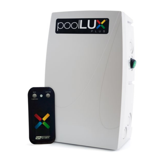
- Page 1 Plus pLX-PL60 & pLX-PL100 5005508 ETL LISTED Conforms to UL STD 379; Certified to CSA STD C22.2 #218.1 Installation Instructions Read all instructions before attempting to perform installation work Type 3R Rainproof Enclosure FOR USE WITH POOL AND SPA PRODUCTS...
-
Page 3: Table Of Contents
Contents IMPORTANT SAFETY INFORMATION ....... . 4 RF Exposure Statement ..........5 IC Statement. -
Page 4: Important Safety Information
NEC ANSI/NFPA 70 and Article 680. The poolLUX Plus (p/n pLX-PL60/PL100) must be mounted on a flat vertical surface. The unit must be a minimum of 4 inches above the ground level, pool deck, or higher than 8 inches above the maximum pool water level, whichever provides greatest elevation. -
Page 5: Rf Exposure Statement
(1) this device may not cause harmful interference, and (2) this device must accept any interference received, including interference that may cause undesired operation. Changes or modifications not expressly approved by S.R.Smith, LLC will void the user’s authority to operate the equipment. -
Page 6: Electrical Ratings
In addition, this fuse is fast acting which helps protect against abnormal electrical conditions that can lead to an unsafe operating condition. *ONLY USE SR SMITH REPLACEMENT FUSES: pLX-PL60 (Part Number: 36-15017-00) / pLX-PL100 (Part Number: 36-15018-00) R e c o m m e n d e d To o l s a n d S u p p l i e s Circular hole saw for installation of 3/4"... -
Page 7: Installation Instructions
LOCAL REGULATORY REQUIREMENTS. E n c l o s u r e m o u n t i n g Locate the poolLUX Plus (p/n pLX-PL60/PL100) in an appropriate area that meets the following requirements: a. Must be mounted on a flat vertical surface. - Page 8 The screw head must be 1 1/8” away from the wall to allow the unit to be mounted correctly. Place the mounting tab of the poolLUX Plus (p/n pLX-PL60/PL100) over the #10 screw and let it hang in place. Level the unit and mark the remaining 2 mounting screw locations on the wall.
-
Page 9: Input / Supply Line Voltage
I n p u t / S u p p l y L i n e V o l t a g e Remove the metal input voltage isolation barrier by unscrewing the mounting screw. Once the securing screw is removed, the isolation cover will pull straight out to allow easier access to the conduit knockout locations. -
Page 10: Output Wiring For Lights And Light Sources
O u t p u t W i r i n g f o r L i g h t s a n d L i g h t S o u r c e s The combined load of all lights connected to the poolLUX Power must not exceed the following: • pLX-PL60 = 60 watts max • pLX-PL100 = 100 watts max The enclosure provides four (4) output conduit locations. - Page 11 Using a hole saw, open the knockout for the size of the conduit (¾" or 1") being installed. Bring output conduits to the open conduit locations. Any conduit used as output wiring runs between the lights and pLX-Plus unit (p/n pLX-PL60/PL100) and any external controller shall be Non-Metallic (Polymeric).
-
Page 12: Operating Instructions
O P E R A T I N G I N S T R U C T I O N S M a n u a l R o c k e r S w i t c h O p e r a t i o n The poolLUX Plus comes with one rocker switch for operation. -
Page 13: Wireless Remote Operation
W i r e l e s s R e m o t e O p e r a t i o n The new poolLUX Plus wireless remote system is shipped ready to use and requires no additional programming. In the event that another poolLUX Plus or similar device is installed nearby and is operating on the same pairing code, that code may be easily changed by setting an alternative code via the 4 position DIP switch inside the battery compartment of the remote. -
Page 14: Wiring Diagram
W I R I N G D I A G R A M REMOTE NOTES: UNLESS OTHERWISE SPECIFIED TRANSFORMER 1. WIRE COLOR LEGEND: R = RED W = WHITE BK = BLACK B = BLUE Y = YELLOW G = GROUND 2. -
Page 15: Replacement Parts
R E P L A C E M E N T P A R T S Replacement parts for the poolLUX Plus (pLX-PL60 or pLX-PL100): Transformer (pLX-PL60) 44-15039-00 Transformer (pLX-PL100) 44-15040-00 3-Way Switch 38-15002-01 Isolation Barrier 02-15342-00 Isolation Barrier mounting screw, 8-32... - Page 16 Questions? 1-800-824-4387 Contact One of Our Dedicated Lighting Specialists. x4012 or x2282 S.R.Smith, LLC P.O. Box 400 | Canby, OR 97013 P 503.266.2231 TF 800.824.4387 srsmith.com © 2017 S.R.Smith. All rights reserved. 79-15264-00 Rev A...
Need help?
Do you have a question about the pLX-PL60 and is the answer not in the manual?
Questions and answers