Table of Contents
Advertisement
Quick Links
Advertisement
Table of Contents

Related Manuals for S.R.Smith Power Tower PT-6002


Summary of Contents for S.R.Smith Power Tower PT-6002
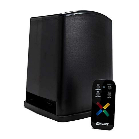
- Page 1 PT-6002 Power Tower ™ ETL LISTED Conforms to UL STD 379; Certified to CSA STD C22.2 #218.1 4 0 0 8 8 1 4 Installation Instructions Read all instructions before attempting to perform installation work FOR USE WITH POOL AND SPA PRODUCTS 79-15280-01 Rev A0...
-
Page 3: Table Of Contents
Contents IMPORTANT SAFETY INFORMATION ..... 4 FCC WARNING ........4 SPECIFICATIONS . -
Page 4: Important Safety Information
I M P O R T A N T S A F E T Y I N F O R M A T I O N ELECTRICAL SHOCK HAZARD – SWITCH DOES NOT TURN OFF INPUT POWER. Failure to disconnect input power before servicing can lead to serious injury, or death. Disconnect input power before servicing. -
Page 5: Specifications
S P E C I F I C A T I O N S ELECTRICAL RATINGS CAUTION: THE EQUIPMENT AND Input Voltage required: 120VAC 60Hz CONTROLS SHALL BE LOCATED NOT Input: 120VAC, 60Hz, 1.2A max LESS THAN 1 M HORIZONTALLY Output: 12-13 VAC, 60 Watts (x2) max FROM THE SPA OR HOT TUB ATTENTION:... -
Page 6: Installation Guidelines
I N S T A L L A T I O N G U I D E L I N E S REFER TO THE DIAGRAMS BELOW FOR THE FOLLOWING PROCEDURES This manual covers the PT-6002 Power Tower installati on only. However, note that existi ng conduits leading from each light locati on in the pool should be: •... - Page 7 Connect 120VAC power INPUT wiring to the unit’s 3-wire cage clamp. 1. Place the unit on the opti onal PT-BASE or the existi ng base from the previous illuminator. Pull the supply cable unti l it extends beyond the end of the conduit in the base from 6 to 8ʺ . Att ach the PT-6002 to the base with 2 of the supplied screws.
- Page 8 12V Power Output Terminals Circuit 1 = left bank, Circuit 2 = right bank Output terminals are connected together in parallel to increase available outputs (Figure D). Each left-right pair is designated for one 12VAC device (common and hot) connection. Seven positions are provided but you may only connect as many 12VAC devices as the cumulative wattage consumption of 60W or less will allow.
-
Page 9: Stand-Alone Environment & Operation
S T A N D - A L O N E E N V I R O N M E N T & O P E R A T I O N The PT-6002 input will be connected to un-switched line voltage (through NEC appropriate GFCI breaker) and can be operated manually by the on-board, 3-position switches or the included hand-held remote control. -
Page 10: Electrical Protection Measures
ELECTRICAL PROTECTION MEASURES Electrical Fusing 1. Self-Resetting Thermal Fuse: This fuse keeps the unit from overheating in instances where a load in excess of the transformer’s capacity is present for an extended period of time. Once normal operating temperatures return, the unit will reset and operation will continue. 2. -
Page 11: Wireless Remote Operation
W I R E L E S S R E M O T E O P E R A T I O N The RF remote system requires no complex programming and is shipped ready to use. In the event that another PT-6002 or similar device is installed nearby and is operating on the same pairing code, that code (A-P) may be easily changed by choosing another via the 4 position DIP switch package found inside the battery compartment of the remote. -
Page 12: Troubleshooting
For Lighting product warranty information and details, please visit our website: www.srsmith.com/warranty Instrucciones de instalación disponibles en español en www.srsmith.com. Questions? Contact One of Our Dedicated Lighting Specialists. x4012 or x2282 1-800-824-4387 S.R.Smith, LLC 800.824.4387 srsmith.com © 2019 S.R.Smith. All rights reserved. 79-15281-00 08/19...
Need help?
Do you have a question about the Power Tower PT-6002 and is the answer not in the manual?
Questions and answers