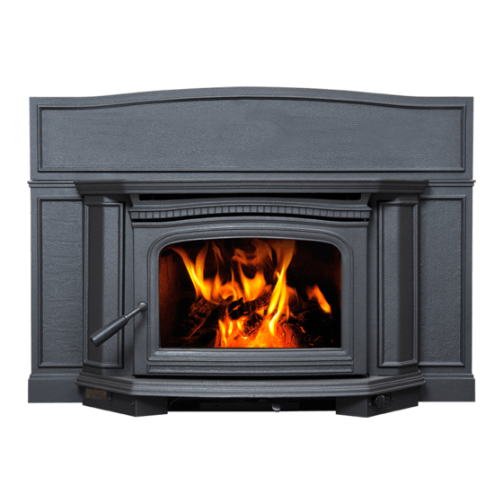
Pacific energy Alderlea T5 LE Insert Installation And Operating Instructions Manual
Hide thumbs
Also See for Alderlea T5 LE Insert:
- Operating and installation instructions (28 pages) ,
- Operating and installation instructions (28 pages) ,
- Installation and operating instructions manual (32 pages)
Table of Contents
Advertisement
Quick Links
IMPORTANT:
THESE INSTRUCTIONS ARE TO
REMAIN WITH THE HOMEOWNER
SAVE THESE INSTRUCTIONS
SAFETY NOTICE
If this stove is not properly installed, a house fire
may result. For your safety, follow the installation
instructions. Contact local building or fire officials
about restrictions and installation inspection
requirements in your area.
Meets the U.S. Environmental Protection
Agency's May 2020 Particulate Emission
Standards.
Visit www.pacificenergy.net for the most recent version of this manual
230819-32
SERIAL #
INSTALLATION
AND OPERATING
INSTRUCTIONS
MODELS:
ALDERLEA T5 LE INSERT
ALT5.INSERT LE
100003038-50
Advertisement
Table of Contents

Related Manuals for Pacific energy Alderlea T5 LE Insert


Summary of Contents for Pacific energy Alderlea T5 LE Insert
-
Page 1: Safety Notice
Contact local building or fire officials about restrictions and installation inspection requirements in your area. Meets the U.S. Environmental Protection Agency's May 2020 Particulate Emission Standards. MODELS: ALDERLEA T5 LE INSERT Visit www.pacificenergy.net for the most recent version of this manual 230819-32 ALT5.INSERT LE 100003038-50... -
Page 2: Table Of Contents
Baffle: ...............10 PLEASE SAVE THESE INSTRUCTIONS This manual describes the installation and operation of the Pacific Energy, ALDERLEA T5 INSERT LE; Fireplace Insert wood heater. Please read this entire manual before you install and use your new room heater. Failure to follow instructions may result in property damage, bodily injury, or even death. -
Page 3: Rating Label
Rating Label This heater meets the 2020 U.S. Environmental Protection Agency’s crib wood emission limits for wood heaters sold after May 15, 2015. Under specific test conditions this heater has been shown to deliver heat at rates ranging from 16,102 to 41,275 Btu/hr. Efficiency and BTU Output EPA Certified Emissions 1.8 grams per hour... -
Page 4: Safety
Safety CAUTION: Never use gasoline type lantern fuel, kerosene, charcoal lighter fluid or similar liquids to start or "freshen up" a fire in this heater. Keep all such liquids well away from the heater while it is in use. Instruct all members of your family on the safe operation of the heater. Ensure they have enough knowledge of the entire system if they are expected to operate it. -
Page 5: To Avoid A Chimney Fire
To Avoid a Chimney Fire 1. Burn wood cleanly. Do not burn wet wood or turn down the unit too quickly after loading. 2. Do not let creosote build up to a point where a chimney fire is possible. 3. Do not have fires in the heater that may ignite chimney fires. These are excessively hot fires, such as when burning household trash, cardboard, Christmas tree limbs, or even ordinary fuel wood;... -
Page 6: Operation
Operation CAUTION: Hot while in operation. Keep children, clothing and furniture away. Contact may cause skin burns. WARNING: Always keep loading door closed when burning. This heater is not designed for open door burning. WARNING: No alteration or modification of the combustion air control assembly is permitted. Any tampering will void warranty and could be very hazardous. -
Page 7: Lighting A Fire
Lighting a fire WARNING: Never use chemicals or any other volatile liquid to start a fire. Do not burn garbage, or flammable fluids such as gasoline, naptha, or engine oil. 1. Adjust air control to “High” position(all the way to the left) and open door. 2. -
Page 8: Convection Blower Operation
Convection Blower Operation The Insert comes equipped with twin variable speed circulating air blowers. The blower system is thermostatically controlled for automatic operation, as well as manually with a convenient bypass switch. Automatic Blower Operation: Allows the blowers to turn on automatically once the Insert has come up to operating temperature. -
Page 9: Maintenance
DOOR GASKETS - The gasket used by Pacific Energy (5/16” medium density fiberglass rope) requires only light pressure to seal. This will prolong seal life. It is important that the door seal be maintained in good condition. Periodically inspect seals and replace if necessary. -
Page 10: Maintenance Checks
Tilt baffle sideways to drop down and remove from firebox. Inspect gasket between baffle and supply tube. If necessary, replace with gasket part number 80000365, available from your Pacific Energy dealer. Re-install baffle assembly in reverse order. The two side pieces of insulation must be tight against the side rails. -
Page 11: Dimensions
Dimensions 1/2 " 545mm 7/8 " 530mm " 430mm 1/2 " ” 1080mm 265mm ” 645mm ” Surround Heights 560mm Dimension Standard Oversized 1/4 " 7/8 " 3/8 " 1/8 " 210mm 455mm 770mm 865mm 3/4 " 1/8 " 3/8 " 5/8 "... -
Page 12: Minimum Fireplace And Hearth Dimensions
Minimum Fireplace and Hearth Dimensions ” 660mm ” 570mm ” 535mm ” 465mm ” Fireplace Hearth ” 406mm 200mm Figure 3: Fireplace opening dim. - ALT5 Insert LE. Hearth Requirements: The fireplace's non-combustible masonry hearth must extend 16” in front and 8” beyond each side of the existing fireplace opening. -
Page 13: Ember Protection
Ember Protection: Combustible flooring in front of the fireplace insert must be protected from hot embers by non-combustible material extending; • Canada - 18” to the firing side (From the Glass) and 8” to each side of the unit. • U.S.A. -
Page 14: Clearances
Clearances The minimum required clearances to surrounding combustible materials when installed into a masonry or factory built fireplace are listed below and in Figure 5. Mantel or Top Facing 12" 305mm 6” 155mm 10” 254mm e n t j a c Fireplace hearth Figure 5: Clearances - ALT 5 Insert LE. -
Page 15: Installation
Installation Your Insert is designed to be installed into a masonry or factory-built, zero-clearance wood burning fireplace. The masonry fireplace must be built according to the requirements of the Standard of Chimneys, Fireplaces, Vents and Solid Fuel Burning appliances, N.F.P.A. 211 (Latest Edition) or applicable National, Provincial, State or local codes. -
Page 16: Full Flue Liner - (Required In Canada)
Full Flue Liner - (Required in Canada) In Canada, this Fireplace Insert must be installed with a continuous chimney liner extending from the Fireplace Insert’s Flue Collar to the top of the chimney. The chimney liner must conform to the class 3 requirements of CAN/ULC-B365, Standard for Lining Systems for Existing Masonry or Factory-Built Chimneys and Vents, or CAN/ULC-S640, Standard for Lining Systems for New Masonry Chimneys. -
Page 17: Direct Flue Connection (Permitted Only In The Usa)
Direct Flue Connection (permitted only in the USA) Pacific Energy highly recommends the use of a full liner as the safest installation and providing optimum per- formance. When connected to a full liner, the Insert is able to draft correctly and will prevent problems such as difficult start-ups and smoking out the door. -
Page 18: Into A Factory Built Fireplace
Into a Factory Built Fireplace Your Insert may be installed into a factory built fireplace (size permitting) with the following requirements: 1. Inspect your fireplace for damage or other physical defects. The fireplace must be in good working condition. If in doubt about its condition, seek professional advice. Check for creosote build up or other obstructions inside the chimney, especially if it has not been in use for some time. -
Page 19: Electrical Supply
Electrical Supply Circulating air blower electrical rating; 115V, 60 Hz, 1.2 A. For your protection against shock hazard, use only a properly grounded outlet that will accept a three-pronged plug. Do not cut or remove the grounding prong. Do not route power cord under unit. Power cord must be routed to avoid contact with any hot or sharp surfaces. -
Page 20: Surround Assembly And Installation
Surround Assembly and Installation 1. Remove crate and all plastic packaging. 2. Remove Top (A) by lifting up on the front edge and pulling towards you. Caution the Fan Shields (B) (Figure 11) may fall. Remove Shields by lifting up and to the sides. 3. - Page 21 Air inlet Surround side Figure 16: Installing fan shield. Figure 15: Install surround to firebox. 6. Attach surround to firebox by aligning with bracket studs (L) then fasten with washers and nuts (M) on each side (Figure 15). 7. Install fan shield as shown in Figure 16. Be sure to place the air inlet opening against the surround side. Slot Figure 17: Decorative cover installation.
-
Page 22: Fan Speed Controller Relocation
Fan Speed Controller Relocation The fan speed controller is factory installed under the ash lip on the right hand side. If required, it can be relocated to the left side by following the instructions below. To make this as easy as possible, it is suggested that this be done prior to fitting the surround and installation into the fireplace: 1. - Page 23 Loosen ash lip bolts Remove screws and clips Figure 23: Ash lip bolts. Figure 24: Remove speed control screws and clips. 4. Loosen the two bolts that secure the ash lip to the firebox (Figure 23), carefully lift up the ash lip and remove from the firebox.
- Page 24 Thermal snap switch Figure 29: Reconnecting fan wires. Figure 30: Re-attaching thermal snap switch. 9. Reconnect the wires to the fans (Figure 29) and re-attach thermal snap switch (Figure 30). Refit ash lip, sides and top. Ensure that the power cable is correctly routed through the surround and it is not touching the firebox side (Figure 31).
-
Page 25: Fan Removal/Installation
Fan Removal/Installation 1. Remove Decorative Top and both Fan shields as specified in”Fan Speed Controller Relocation” on page 2. Disconnect fan wires as shown in Figure 32 from appropriate fan that is being replaced. Remove Thermal switch if needed (Figure 33). 3. -
Page 26: Troubleshooting
Troubleshooting Problem Cause Cure Excessive Creosote 1) Wood is too wet - Use dry wood Buildup Turning down air control - Do not turn down until: too soon a) there is a good bed of coals b) the wood is charred Draft too low - Improper chimney height and/or diameter - Chimney plugged or restricted, check flue... -
Page 27: Firebrick Installation
Firebrick Installation ITEM SIZE 18pcs. 9” x 4 1/2” x 1 1/4” (230 mm x 115 mm x 32 mm) 2pcs. 4 1/2” x 1 1/2” x 1 1/4” (115 mm x 38 mm x 32 mm) Figure 34: Bottom shield. 1. - Page 28 3. Place four bricks along the left hand wall. Insert the bricks and slide them forward, so that they are kept in place behind the rail tabs (Figure 38). Figure 36: Cover in place. Figure 35: Empty firebox. Figure 37: Floor bricks in place. Figure 38: Left wall bricks in place.
- Page 29 This page is intentionally left blank. 100003038 ALT5 LE Insert 230819-32...
-
Page 30: Replacement Parts
Replacement Parts (WHEN ORDERING, INCLUDE PART NUMBER WITH DESCRIPTION) ITEM DESCRIPTION PART NO. 1..Casting, ALT 5 Insert, Top, Painted ..................80000713 ..Casting, ALT 5 Insert, Top, Majolica Brown Enamel ..............80000060 ..Casting, ALT 5 Insert, Top, Antique White Enamel ..............80000058 2.. - Page 31 Parts may be ordered from your nearest Pacific Energy dealer. Contact Pacific Energy for the location of the dealer nearest you. 100003038 ALT5 LE Insert 230819-32...
- Page 32 © 2019 Copyright Pacific Energy Fireplace Products LTD. Reproduction, adaptation, or translation without prior written permission is prohibited except as allowed under the copyright laws. For technical support, please contact your retailer Web site: www.pacificenergy.net 2975 Allenby Rd., Duncan, BC V9l 6V8...
Need help?
Do you have a question about the Alderlea T5 LE Insert and is the answer not in the manual?
Questions and answers